Understanding Ceramic Capacitors: Types, Uses, and Selection Guide
2025.01.19
From the smartphone in your pocket to the complex circuitry of a satellite, ceramic capacitors play a critical role in modern electronics. These tiny but powerful components, especially the widely used Multilayer Ceramic Capacitors (MLCC), help store and release electrical energy, enabling countless technological advancements. In this guide, we will dive into the world of ceramic capacitors, explaining their construction, types, uses, and selection criteria, providing you with the knowledge needed to make the right choice for your electronic projects.
What are Ceramic Capacitors?
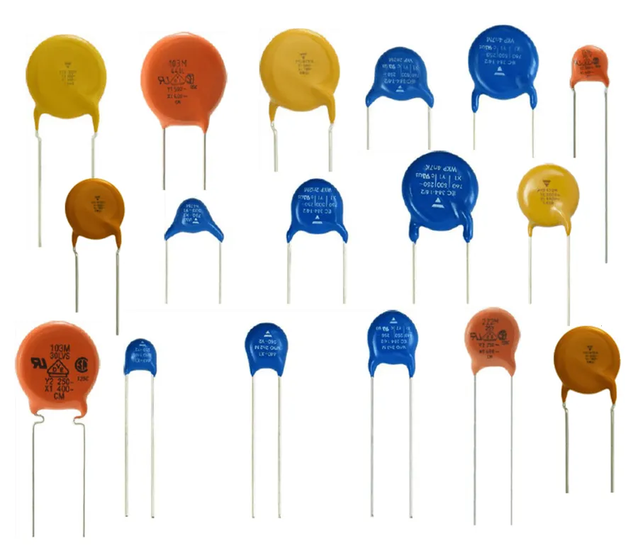
Ceramic Capacitors
Ceramic capacitors are a ubiquitous type of capacitor characterized by their construction, which involves alternating layers of a ceramic dielectric material and metal electrodes. This layered structure enables them to store electrical energy and exhibit unique properties such as their non-polarized nature and compact form factor, making them suitable for a wide range of applications in electronic circuits.
At their core, ceramic capacitors leverage the dielectric properties of ceramic materials, which when subjected to an electric field, polarize, thus storing energy. The non-polarized nature of these capacitors means that they can be connected into a circuit without the constraints of a specific orientation, unlike electrolytic capacitors.
These capacitors are available in a multitude of form factors, from tiny surface-mount devices (SMD) to larger leaded components, allowing for versatile integration into various circuit designs. Their inherent compactness is particularly advantageous in modern electronics where space efficiency is critical, and their electrical characteristics lend them well to use in high-frequency applications.
Types of Ceramic Capacitors: MLCC and SMD
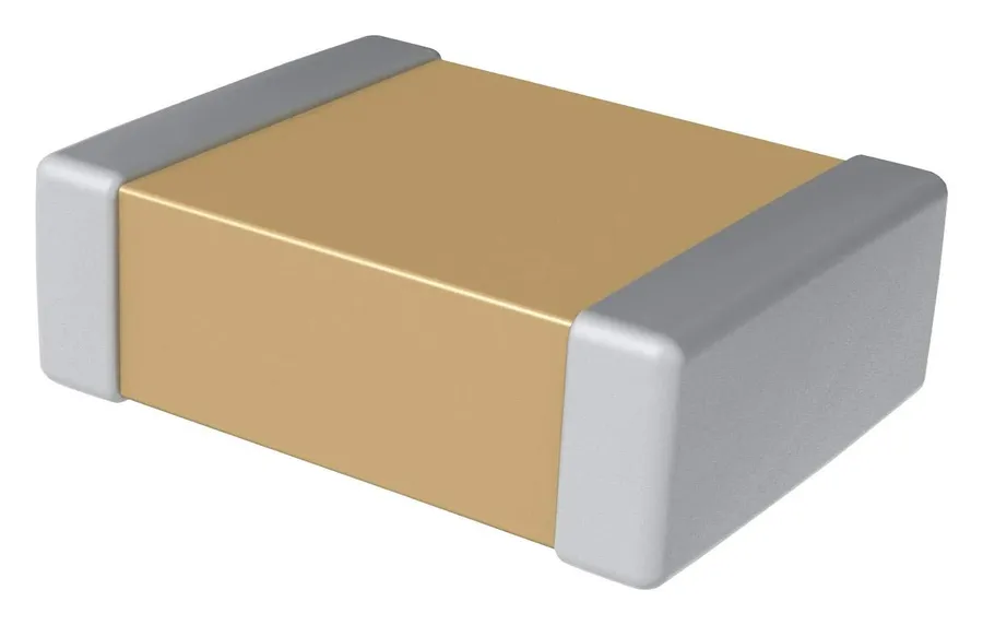
SMD Capacitors
Ceramic capacitors are primarily categorized into Multilayer Ceramic Capacitors (MLCC) and Surface Mount Devices (SMD), each distinguished by their construction and application suitability. Understanding these types is crucial for selecting the correct component for electronic circuit design.
May have higher component costs for specific packages
MLCCs (Multilayer Ceramic Capacitors) are constructed from alternating layers of ceramic dielectric and metal electrodes, creating a compact device with a high capacitance-to-volume ratio. This multilayer structure allows for the creation of high-capacitance components in relatively small sizes. These capacitors offer a wide range of capacitance values and are widely used in decoupling, bypass, and filtering applications, They are available in both leaded and surface mount packages, enabling them to be integrated into a wide variety of circuit designs.
SMD (Surface Mount Device) ceramic capacitors are designed without leads, which allow them to be directly mounted onto the surface of a printed circuit board (PCB). This leadless design enables more efficient automatic assembly processes. SMDs also offer a reduced size and improved electrical performance, such as lower parasitic inductance, which makes them ideal for high-frequency applications. These components are crucial in modern electronics where board space is at a premium, such as smartphones, tablets, and wearable devices.
Ceramic Capacitor Manufacturing Process
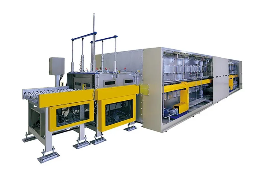
Capacitor Production Line
The manufacturing process of ceramic capacitors is a complex and precise undertaking, involving multiple stages to transform raw materials into functional electronic components. It requires controlled environments and meticulous execution to ensure the capacitors meet strict performance and reliability standards. This section details the key steps involved in this process.
Raw Material Preparation The process begins with the careful selection and preparation of raw materials. This mainly includes ceramic powders (such as barium titanate) and metal powders (typically nickel or silver for electrodes). These materials are precisely measured and mixed to achieve the desired electrical characteristics of the capacitor. The purity, particle size distribution, and stoichiometry of these materials are critical factors influencing the capacitor's performance.
Tape Casting or Layer Formation The mixed ceramic powder is then combined with binders, solvents, and plasticizers to form a ceramic slurry. This slurry is then cast into thin ceramic layers, or 'tapes', using a process called tape casting. The tape thickness is carefully controlled, usually in the micrometer range, as it directly impacts the capacitance. For MLCC (Multilayer Ceramic Capacitors), multiple layers are needed. These layers are printed with conductive electrode patterns.
Electrode Printing Metal electrodes are precisely applied onto the ceramic layers using screen printing or similar methods. The type of metal used (nickel, silver, etc.) and the thickness of the electrode layers are carefully controlled to achieve the desired capacitor characteristics. This step is crucial for the precise control of electrical characteristics.
Layer Stacking and Lamination The printed ceramic layers are then stacked together in precise alignment, typically in a staggered fashion. They are then laminated under high pressure and controlled temperature, which effectively bonds the layers together, ensuring proper contact between electrodes and ceramic material, forming a monolithic structure.
Sintering The laminated stack is then subjected to a high-temperature sintering process. Sintering is a crucial heat treatment process where the materials are heated to a high temperature (below their melting point) causing the ceramic particles to bond together, forming a dense, solid structure. This process eliminates voids and increases the mechanical and electrical integrity of the capacitor. The sintering temperature profile is precisely controlled to achieve the desired microstructural properties.
Termination and Testing After sintering, the individual capacitors are diced or separated from the sintered block. Metal terminations are added to the exposed electrode edges to allow for external connection. Finally, each capacitor is thoroughly tested for capacitance, voltage rating, tolerance, and other performance characteristics before being packaged for distribution.
Key Parameters of Ceramic Capacitors: Capacitance, Voltage, and Tolerance
Selecting the appropriate ceramic capacitor for a given application requires a thorough understanding of its key electrical parameters. These parameters, namely capacitance, voltage rating, and tolerance, are crucial for ensuring the capacitor functions correctly within the intended circuit. Furthermore, consideration must be given to how temperature and frequency affect these parameters.
Parameter
Description
Units
Importance
Capacitance
The ability of the capacitor to store electrical charge.
Farads (F), typically microfarads (µF), nanofarads (nF), or picofarads (pF) for ceramic capacitors.
Determines the capacitor's effectiveness in storing energy and its behavior in AC circuits.
Voltage Rating
The maximum voltage that can be safely applied across the capacitor without causing damage or failure.
Volts (V)
Critical to prevent dielectric breakdown and ensure long-term reliability. Operating beyond the voltage rating will lead to capacitor failure.
Tolerance
The permissible deviation of the actual capacitance value from its nominal value.
Percentage (%) or specific code
Indicates the precision of the capacitor's manufacturing process and its suitability for specific circuits. Precision requirements depend on the application.
Temperature Coefficient
Describes the change in capacitance value with temperature variation.
PPM/°C (parts per million per degree Celsius)
Indicates how capacitance changes with temperature; critical for circuits operating in environments with large temperature variations.
Frequency Response
Describes how capacitance behaves with variations in frequency.
Various, frequency response curves are typically provided in datasheets
Capacitance of a ceramic capacitor may change with frequency. Knowing this response is vital when operating in high frequency applications.
Temperature and frequency considerations: Ceramic capacitors exhibit temperature and frequency dependence. Understanding the temperature coefficient is critical for stable performance across a wide temperature range. The effects of frequency on impedance are also important, particularly in high-frequency circuits.
Applications of Ceramic Capacitors
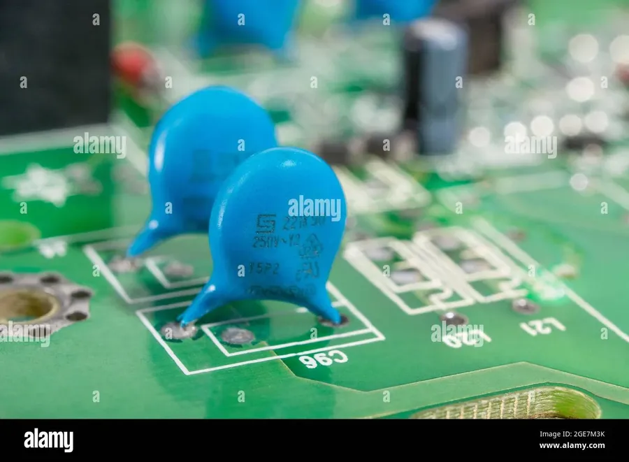
Capacitors on PCB
Ceramic capacitors are ubiquitous in modern electronics due to their versatility and performance characteristics, spanning a wide array of applications from basic circuit functions to highly specialized roles. Their ability to operate effectively across various frequencies and temperatures makes them indispensable in many electronic designs.
Bypass Capacitors In bypass applications, ceramic capacitors are placed in parallel with a load, providing a low-impedance path for high-frequency noise to ground. This prevents unwanted noise from propagating through the circuit, ensuring stable and clean power delivery.
Decoupling Capacitors Ceramic capacitors used for decoupling store charge and quickly release it as needed to compensate for voltage drops during rapid load changes in digital circuits, minimizing voltage fluctuations and maintaining signal integrity.
Filtering Ceramic capacitors serve as key components in filter circuits, particularly in low-pass filters where they block high-frequency noise while allowing lower frequency signals to pass through, essential for audio processing and signal conditioning.
Radio Frequency (RF) Circuits Due to their low inductance and high self-resonant frequency, ceramic capacitors are exceptionally well-suited for RF applications such as impedance matching and tuning circuits in wireless communication devices.
Electrostatic Discharge (ESD) Protection Placed strategically on input/output lines, ceramic capacitors act as shunt devices to divert electrostatic discharge events to ground, protecting sensitive integrated circuits from potential damage caused by ESD.
Automotive Electronics In automotive environments, ceramic capacitors are crucial for various applications, including engine control units (ECUs), infotainment systems, and safety systems because of their reliability across a wide range of temperatures and under demanding conditions.
High-Frequency Applications The low equivalent series inductance (ESL) of ceramic capacitors allows for optimal performance in high-speed and high-frequency circuits, ensuring minimal signal distortion in fast digital processing and advanced communication systems.
Advantages and Limitations of Ceramic Capacitors
Ceramic capacitors, while ubiquitous in modern electronics, present a unique set of advantages and limitations that must be carefully considered during circuit design. Their suitability for a particular application hinges on a trade-off between their exceptional high-frequency performance and certain drawbacks related to stability and capacitance range.
Feature
Ceramic Capacitors
Film Capacitors
Electrolytic Capacitors
High Frequency Response
Excellent
Good
Poor
Parasitic Inductance
Very Low
Low
High
Temperature Stability
Variable (Class 1 better)
Good
Poor
Capacitance Range
Limited
Wide
Very Wide
Size
Compact
Larger
Larger
Polarization
Non-Polarized
Non-Polarized
Polarized
Cost
Low
Medium
Low
Typical Applications
High-frequency circuits, decoupling, bypass
Audio circuits, power supplies, timing
High capacitance applications
Advantages: Ceramic capacitors offer several key advantages, making them a cornerstone in many electronic designs.
High-Frequency Performance: Due to their low equivalent series resistance (ESR) and low parasitic inductance, ceramic capacitors excel in high-frequency applications. They exhibit minimal impedance at high frequencies, making them ideal for decoupling and bypass applications where rapid changes in current are common.
Low Parasitic Inductance: Their construction minimizes parasitic inductance, which further improves their performance in high-speed digital and RF circuits. This allows them to act as effective high-frequency filters, reducing noise and signal distortion.
Compact Size: Ceramic capacitors, particularly Multilayer Ceramic Capacitors (MLCCs), can be manufactured in extremely small packages. This is critical for compact devices where space is a premium. The small size also enables higher component density on circuit boards.
Non-Polarized: The non-polarized nature of ceramic capacitors simplifies circuit design by allowing them to be placed without regard to orientation. This reduces design constraints and minimizes assembly errors, which is a significant advantage in complex layouts.
Cost-Effective: Compared to other types of capacitors, ceramic capacitors are relatively inexpensive, especially in high volumes. This makes them suitable for consumer electronics and mass-produced devices, where cost is often a deciding factor.
Limitations: Despite their benefits, ceramic capacitors do have some limitations that must be taken into account when designing a system.
Temperature Stability: The capacitance of ceramic capacitors can vary significantly with temperature, which can be an issue in applications where temperature fluctuations are expected. It's essential to select the appropriate dielectric material to minimize capacitance variations in different operating environments.
Limited Capacitance Range: Compared to electrolytic and film capacitors, ceramic capacitors generally offer a narrower range of available capacitances. This limitation sometimes necessitates the use of multiple capacitors in parallel to achieve the desired capacitance, impacting the design layout and cost.
Voltage Dependence Some ceramic capacitors exhibit voltage dependence, where their capacitance changes with the applied voltage. This non-linearity can affect performance in circuits requiring stable capacitance and should be considered in high voltage applications.
Potential for Cracking Due to their brittle ceramic construction, these capacitors are susceptible to cracking during assembly or due to mechanical stress. This means that proper handling and assembly processes are essential to prevent failures, especially in high-density PCB layouts.
Frequently Asked Questions About Ceramic Capacitors
This section addresses common questions regarding ceramic capacitors, clarifying their applications, distinctions from other capacitor types, and failure modes. We aim to provide concise and informative answers to enhance your understanding of these crucial electronic components.
What are the primary applications of ceramic capacitors? Ceramic capacitors are primarily used in applications requiring high-frequency performance, such as bypass and decoupling, filtering, and RF circuits. Their low inductance and small size make them suitable for applications in high-speed digital circuits and other electronics where space is a constraint. They are also used in power supplies for smoothing and energy storage. The versatility of their applications are further enhanced by their non-polarized nature and good temperature stability which makes them ideal for a wide range of different applications.
How do ceramic capacitors differ from other capacitor types like electrolytic or film capacitors? Ceramic capacitors differ significantly from electrolytic and film capacitors in several key aspects. Ceramic capacitors are non-polarized, have a high-frequency response, and generally have a lower capacitance range and can handle higher voltages relative to electrolytic capacitors of the same physical size. Electrolytic capacitors offer a much larger capacitance but are polarized and have higher equivalent series resistance and inductance, with lower operating frequencies. Film capacitors offer very stable capacitance values with good high-frequency response, they have a lower equivalent series resistance and are very reliable. The choice between these capacitors often hinges on the specific application requirements like the required frequency response, capacitance, and the level of voltage that the device is expected to handle.
Can a film capacitor be replaced with a ceramic capacitor? While it's possible to replace a film capacitor with a ceramic capacitor in certain applications, it requires careful consideration of specifications. Both types offer different advantages. Ceramic capacitors have good high frequency characteristics with low parasitics, and are typically smaller. Film capacitors on the other hand offer greater stability, better precision and higher voltage ratings. Replacing a film capacitor with a ceramic one is not always suitable, as the lower capacitance and temperature instability of a ceramic capacitor can cause circuit performance issues.
What are the typical failure modes of ceramic capacitors? The failure modes of ceramic capacitors include cracking due to mechanical stress, dielectric breakdown from excessive voltage, and capacitance loss over time due to degradation of the ceramic material. They can also fail due to solder reflow temperatures if not properly rated. Environmental factors such as extreme humidity and temperature can also degrade the performance of the component and lead to failure. When a ceramic capacitor fails, it may lead to an open circuit, a short circuit or reduced capacitance, which will typically result in circuit malfunction.
Are ceramic capacitors polarized, and how does that affect circuit design? Ceramic capacitors are non-polarized, meaning they can be connected in a circuit without regard to polarity, unlike electrolytic capacitors. This characteristic simplifies circuit design and implementation, as there is no need to worry about correct polarity when installing. This is advantageous for high-frequency applications or in situations where the voltage across the capacitor might change direction.
What is the meaning of the code printed on ceramic capacitors? The codes printed on ceramic capacitors typically indicate the capacitance value, tolerance, and sometimes the voltage rating. Often, a three-digit or four-digit code system is used where the first two or three digits represent the significant figures of the capacitance value, and the last digit represents the multiplier, often in picofarads (pF). Letters are often used for tolerance. For example, a code like 104 indicates 10 x 10^4 pF or 100 nF, or a code like 100n indicates 100nF, the system used is often manufacturer specific. It's important to consult the manufacturer's datasheets to confirm the decoding method being used and the specifics of the capacitor for correct interpretation of these markings.
Choosing the Right Ceramic Capacitor: A Practical Guide
Capacitor Size Comparison
Selecting the appropriate ceramic capacitor for a specific application requires a careful evaluation of several key factors. These include the electrical parameters, such as capacitance, voltage rating, and tolerance, along with practical constraints like size limitations, environmental conditions, and desired reliability. A methodical approach ensures optimal circuit performance and longevity.
Electrical Parameters Begin by defining the required capacitance value, ensuring it meets the circuit's needs, keeping in mind that the capacitance of ceramic capacitors can vary with temperature and voltage. The capacitor’s voltage rating must exceed the maximum expected voltage in the application by a safe margin. Lastly, tolerance specifies how close the actual capacitance value must be to the nominal value.
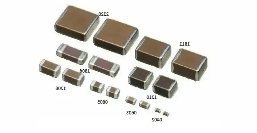
Size Constraints Ceramic capacitors come in various sizes, often designated by standard case sizes, such as 0603, 0805, etc. Select the size that physically fits on the circuit board and also meets the electrical requirements. Smaller sizes tend to have lower capacitance values and voltage ratings.
Environmental Conditions Consider the operating temperature range of the application. Ceramic capacitors have different temperature coefficients, and it's crucial to choose one that provides stable performance over the required temperature range. For example, Class 1 capacitors (C0G/NP0) are highly stable, while Class 2 (X7R, X5R, Y5V) offer higher capacitance but less stability. Also take into consideration humidity, and any potential exposure to corrosive substances.
Reliability Requirements Assess the long-term reliability needed for the application. High-reliability applications, such as medical or aerospace, require capacitors with stringent quality control and extended life testing. Choose manufacturers that provide detailed reliability data on their products. Consider also failure modes, such as short circuits and open circuits, and select capacitors that can mitigate risks.
Specific Application Needs If the application requires low equivalent series resistance (ESR), such as in high-frequency circuits, then consider capacitors specifically designed for low ESR. If the application involves high-voltage stress, make sure to select capacitors with a suitable voltage rating and appropriate safety margins. If the capacitor will be used in a high-current environment then consider the current handling capacity as well.
Parameter
Considerations
Capacitance Value
Must meet the circuit's functional needs. Consider temperature and voltage variation.
Voltage Rating
Should be significantly higher than the maximum operating voltage. Consider potential transients.
Tolerance
Must be within the range of allowable variance for proper circuit function.
Case Size
Must be physically compatible with the circuit board design.
Temperature Coefficient
Choose capacitor class (e.g., C0G, X7R) suitable for the application's temperature requirements.
Reliability
Must meet the long-term performance and quality needs of the application.
Ceramic Capacitor Symbols and Markings
Capacitor Markings
Understanding ceramic capacitor symbols and markings is crucial for proper circuit design and component selection. These markings provide essential information about the capacitor's characteristics, such as its capacitance value and tolerance, enabling engineers and technicians to effectively utilize these components.
Ceramic capacitors, lacking polarity, often use a numerical code for capacitance. This code, combined with the physical symbol on schematics, allows for clear identification within circuit designs.
Capacitance Value Markings Capacitance is typically indicated using a three-digit code. The first two digits represent the significant figures of the capacitance, and the third digit indicates the multiplier. For example, '104' means 10 x 10^4 picofarads (pF), which is equal to 100 nanofarads (nF) or 0.1 microfarads (µF).
Tolerance Codes Tolerance is often specified by a letter code that follows the capacitance value, indicating the acceptable deviation from the stated capacitance. Standard codes include J (±5%), K (±10%), and M (±20%).
Voltage Rating Markings Some ceramic capacitors have voltage ratings marked on their body. These ratings should be strictly adhered to in circuit design to prevent capacitor failure.
Code
Multiplier
Example
Capacitance
102
x 10^2
102
1000 pF
103
x 10^3
103
10000 pF
104
x 10^4
104
100,000 pF (100 nF or 0.1 μF)
225
x 10^5
225
2,200,000 pF (2.2 μF)
Letter Code
Tolerance (%)
B
±0.10
C
±0.25
D
±0.5
F
±1
G
±2
J
±5
K
±10
M
±20
In schematic diagrams, ceramic capacitors are represented by a standard symbol consisting of two parallel lines, often with curved or straight lines indicating specific configurations of the part. The symbol lacks polarity markings, reflecting the capacitor's non-polarized nature.
Ceramic capacitors, including the ubiquitous MLCC, are foundational components in modern electronics. Their small size, non-polarized nature, and high-frequency performance make them suitable for various applications. By understanding their characteristics and how to select them properly, you can improve the performance and reliability of your designs. Remember to always consider the specific demands of your project when choosing a ceramic capacitor. As technology evolves, ceramic capacitors will continue to be instrumental in powering future innovations, continuing to shape our world.