
In the fast-paced world of automotive engineering, the shift toward complex, miniaturized electronic systems has made flex-rigid PCBs a mission-critical component. However, the intersection of rigid and flexible layers introduces unique failure points that can jeopardize hardware longevity. This guide provides the authoritative DFM standards you need to ensure your assemblies survive the rigorous mechanical and thermal demands of the road.
Understanding the Automotive Flex-Rigid Lifecycle
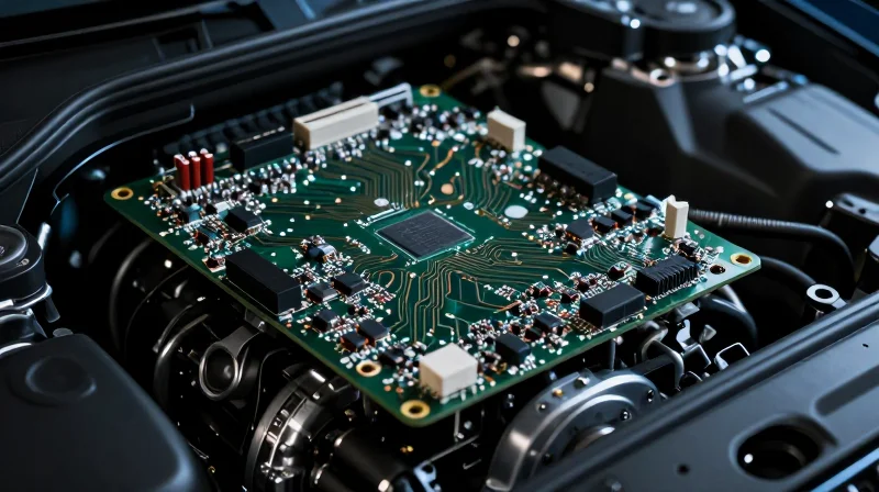
Navigating Environmental Stressors
Designing for the automotive lifecycle necessitates a shift from consumer-grade reliability to mission-critical endurance. Unlike standard electronic assemblies, flex-rigid harnesses in automotive applications must maintain signal integrity while undergoing constant physical transformation due to engine-induced vibrations and extreme temperature fluctuations.
| Environmental Stressor | Primary Failure Mode | DFM Mitigation Strategy |
|---|---|---|
| Thermal Cycling | Interconnect fatigue/delamination | Match CTE of materials to substrate |
| Vibration/Shock | Solder joint cracking | Optimized bend radius and strain relief |
| Moisture Ingress | Electrochemical migration | Advanced conformal coating and sealing |
Key Lifecycle Considerations
- Why is CTE matching critical for flex-rigid designs?
Coefficient of Thermal Expansion (CTE) mismatch between the rigid FR4 and flexible polyimide layers causes stress concentrations at the transition zone during thermal cycling, leading to layer separation. - How does vibration influence mechanical routing?
Automotive environments introduce high-frequency resonance. Proper DFM requires 'slack' in the flexible regions and secured anchoring points to prevent fatigue at the rigid-to-flex junction. - What role does moisture play in reliability?
Moisture ingress promotes dendrite growth and shorts, especially in high-density interconnects. Encapsulation techniques are mandatory to seal the assembly from humidity and automotive fluids.
By acknowledging these variables early in the DFM process, engineers can implement 'reliability by design' principles, effectively extending the lifespan of the wiring harness across the vehicle's entire operational duty cycle.
Material Selection: Balancing Flexibility and Thermal Stability
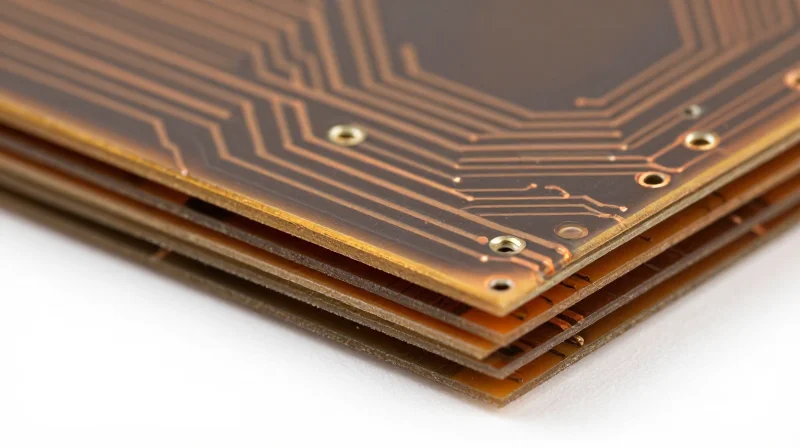
In automotive-grade flex-rigid PCB design, material selection is the primary defense against long-term fatigue failure. Engineers must balance the high glass transition temperature (Tg) requirements of under-hood environments with the necessary mechanical flexibility to prevent fractures during vibration. Adherence to IPC-4204 standards ensures that the polyimide substrates and bonding agents maintain structural integrity across a broad thermal range, typically from -40°C to +150°C.
Core Material Selection Criteria
| Material Type | Key Property | Automotive Application Benefit |
|---|---|---|
| High-Tg Polyimide | Tg > 200°C | Resists delamination during thermal cycling |
| Acrylic Adhesive | High bond strength | Excellent flexibility for dynamic folding |
| Modified Epoxy | Moisture resistance | Prevents dendritic growth and shorts |
Frequently Asked Questions on DFM Material Compatibility
- Why is adhesive selection critical for flex-rigid reliability?
Adhesives act as the bridge between rigid FR-4 and flexible polyimide layers; mismatch in Coefficients of Thermal Expansion (CTE) can lead to barrel cracking or pad cratering during rapid temperature transitions. - How does moisture ingress affect material choice?
Polyimides are hygroscopic by nature. Utilizing low-moisture-absorption coverlays and high-performance moisture barriers is essential to prevent ionic migration and potential corrosion in high-humidity automotive environments. - Is standard coverlay sufficient for automotive vibrations?
Standard coverlays may experience fatigue-induced embrittlement. Automotive-grade specifications require high-elongation polyimide types to handle the mechanical stresses of wiring harness routing and vehicle vibration.
Implementation Strategy
For designs exceeding 125°C operational temperatures, consider adhesive-less copper-polyimide laminates. These remove the weak thermal link of the adhesive layer, significantly improving Z-axis stability and reducing the risk of delamination during the reflow process. Always ensure that the thermal expansion coefficient of the coverlay matches the internal copper traces to minimize residual stress buildup.
Copper Weight Optimization for Dynamic Flexing
Copper Weight Optimization for Dynamic Flexing
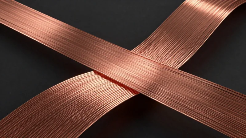
In automotive-grade flex-rigid assemblies, the copper weight directly correlates to the mechanical strain experienced by conductors during lifecycle flexing. Excessive copper thickness increases the neutral axis offset, leading to higher stress concentrations on the outer layers of the trace. To ensure long-term reliability, designers must prioritize thin, rolled-annealed (RA) copper foil to maintain flexibility while minimizing the risk of work hardening and eventual fatigue-induced cracking.
Strategic Material and Weight Selection
The industry standard for automotive dynamic applications is the use of rolled-annealed copper, which features a horizontal grain structure superior to electro-deposited (ED) copper in terms of bending endurance. For high-flex requirements, designers should specify the thinnest possible copper weight that fulfills electrical current and impedance requirements.
| Copper Weight | Application Focus | Flex Life Expectancy |
|---|---|---|
| 1/3 oz (12µm) | High-cycle dynamic flexing | Excellent |
| 1/2 oz (18µm) | Standard flex-to-install | Good |
| 1 oz (35µm) | Rigid areas/low-cycle | Limited |
DFM Guidelines for Trace Geometry
- Why should I avoid heavy copper weights in dynamic flex areas?
Heavier copper shifts the neutral axis further away from the center, which exponentially increases stress on the copper during bending, leading to early brittle fracture. - What is the benefit of using Rolled-Annealed (RA) copper?
RA copper provides a linear grain structure that allows the material to elongate and deform under stress without developing micro-cracks, unlike the columnar structure of ED copper. - How can I handle higher current loads without using thick copper?
Instead of increasing copper thickness, increase the width of the traces or utilize multiple parallel traces distributed across the flex zone to maintain the desired current capacity without sacrificing mechanical flexibility. - What is the recommended trace routing technique for flex zones?
Routes should be perpendicular to the bend axis whenever possible, and curves should be used instead of sharp 90-degree angles to distribute mechanical load across a wider surface area.
Mastering the Flex-to-Rigid Transition Zone
Engineering the Interface: Mechanical Reliability
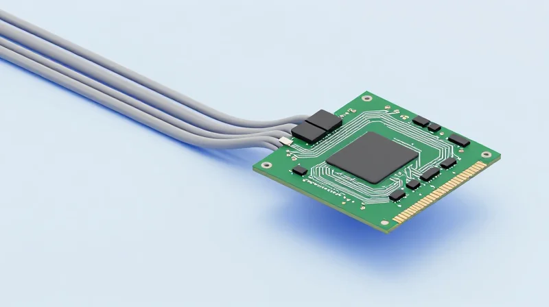
The transition zone—the physical boundary where flexible circuits join the rigid board—acts as a fulcrum for mechanical stress. To prevent delamination or copper fatigue, designers must implement graduated stiffness profiles. Utilizing 'filleted' copper traces in this region reduces localized stress concentrations, while coverlay termination must be set back from the rigid interface to prevent the creation of a 'hard edge' that acts as a pivot point for potential breakage.
Comparison of Reinforcement Techniques
| Technique | Primary Function | Automotive Suitability |
|---|---|---|
| Stress Relief Slots | Distributes mechanical strain away from the via array. | High: Essential for long-term vibration resistance. |
| Resin Flow Control (Damming) | Prevents prepreg/adhesive ingress into the flex portion. | Critical: Prevents embrittlement of the flexible substrate. |
| Stiffener Bonding | Adds local rigidity to support connector headers. | Required: Prevents solder joint fatigue during mating. |
Best Practices for Resin Flow and Drilling
Resin flow control is the primary defense against internal stress buildup within the multi-layer stack-up. Designers should specify 'resin dams' or physical spacing between the flex transition and the first rigid-side via. When performing back-drilling to improve signal integrity, it is vital to keep the drill depth well outside the transition zone to avoid introducing micro-cracks into the polyimide core, which would otherwise become propagation sites for failure during thermal shock cycles.
Frequently Asked Questions
- How far should the coverlay be from the rigid edge?
Coverlay termination should ideally be recessed by 0.25mm to 0.50mm from the rigid board edge to eliminate the 'cliff effect' and allow for slight material expansion during thermal cycling. - Why is back-drilling restricted in the transition zone?
Back-drilling creates residual mechanical stress and heat-affected zones that significantly weaken the flex-to-rigid bond, potentially leading to catastrophic delamination under automotive vibration loads. - Is adhesive-less construction required?
Yes. For high-reliability automotive applications, adhesive-less laminates are preferred to minimize the risk of 'z-axis' expansion, which is the primary cause of plated through-hole failure in rigid-flex interfaces.
Bend Radius Constraints and Mechanical Integrity
In automotive-grade flex-rigid assemblies, the bend radius is not merely a geometric constraint but a primary factor in preventing fatigue-induced failure. Designers must adhere to strict ratio-based limits that account for the cumulative thickness of the flex stack-up, including coverlays, adhesives, and copper layers, to prevent compressive buckling of traces and tensile delamination at the neutral axis.
Mathematical Foundation for Bend Radius Limits
The minimum bend radius (R) for a flex circuit is defined as a multiplier of the total assembly thickness (T). Automotive standards require a more conservative approach than consumer electronics due to vibration profiles and temperature cycling. The following table provides recommended ratios based on flex construction type.
| Construction Type | Min. Radius (Single-Sided) | Min. Radius (Double-Sided) | Design Note |
|---|---|---|---|
| Static Flex | 10x Thickness | 15x Thickness | Used for install-only |
| Dynamic Flex | 20x Thickness | 30x Thickness | Requires RA Copper |
| Multi-layer Flex | 40x Thickness | 50x Thickness | Avoid high-density zones |
Neutral Axis Engineering
To maximize mechanical integrity, the copper traces should ideally reside on the neutral axis of the flex section. By balancing the thickness of the coverlay and the base substrate, the stress experienced by the copper during bending can be minimized. Automotive designers should employ symmetrical stack-ups to ensure the neutral axis remains centered, effectively neutralizing the tensile and compressive forces that cause trace fracture.
Frequently Asked Questions on Bend Reliability
- How does moisture absorption affect bend radius?
Polyimide absorbs moisture, which can swell the dielectric and alter the effective bend radius; automotive designs must include a 15% safety buffer for humidity-induced expansion. - Can I use rigid-style traces in the flex zone?
No; rigid-style traces (longitudinal, square-edged) create stress concentrators. Use curved, teardropped, and staggered (I-beaming) trace patterns to redistribute mechanical loads. - What is the consequence of exceeding the minimum bend radius?
Failure modes include trace cracking (open circuits), dielectric delamination, and impedance shifts due to deformation of the trace geometry during bending.
Stack-up Strategies for Signal Integrity
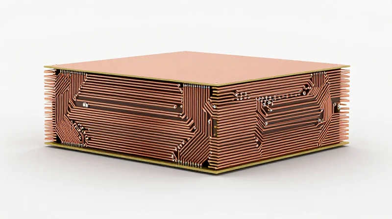
Principles of Balanced Symmetrical Stack-ups
For automotive-grade reliability, stack-ups must be perfectly balanced regarding copper distribution, dielectric thickness, and material modulus to mitigate mechanical stress during the lamination process. Asymmetrical stack-ups often result in latent latent stresses that cause PCB warpage or 'potato-chipping' during reflow soldering. By ensuring that the layup mirrors across the central neutral axis, designers can effectively distribute the CTE (Coefficient of Thermal Expansion) forces, maintaining the structural integrity of the flex-rigid interface.
Impedance Consistency across Flex-Rigid Borders
Transitioning from rigid FR-4 to polyimide flex introduces inherent impedance discontinuities due to dielectric constant (Dk) differences. To maintain signal integrity, designers should employ 'crossover' compensation, where the reference planes are adjusted to match the impedance profile across the entire length of the signal path.
| Material Type | Typical Dk | Performance Impact |
|---|---|---|
| Standard FR-4 | 4.2 - 4.8 | High signal loss at high frequencies |
| High-Tg Polyimide | 3.4 - 3.6 | Excellent stability for flex layers |
| Low-Loss Prepreg | 3.2 - 3.8 | Minimizes dielectric absorption |
- How does copper balancing affect signal integrity?
Uneven copper distribution creates localized thermal pockets during manufacturing, leading to varying trace widths after etching, which directly degrades impedance control. - Why is the neutral axis critical in flex-rigid designs?
The neutral axis minimizes strain on copper traces during bending; keeping high-speed signal layers as close to this axis as possible prevents micro-fracturing of traces. - Can I use blind vias in the flex transition zone?
Avoid using blind or buried vias within the actual bend area; these create stress concentrations that significantly increase the probability of via-barrel cracking.
In practice, always prioritize the usage of 'bookbinder' construction for high-layer-count flex assemblies to accommodate the different bend radii of internal vs. external layers. This technique effectively prevents buckling of inner flex layers while maintaining the mechanical rigidity required for automotive-grade wiring harnesses.
DFM Verification and Simulation Tools

Integrated CAD/CAM Design Rule Verification
Advanced DFM verification begins with automated constraint-based design rule checks (DRC). For automotive applications, standard DRC is insufficient; engineers must employ custom scripts to audit the flex-to-rigid transition, specifically verifying copper weight distribution, annular ring consistency, and coverlay adhesion zones. These automated checks ensure that the design adheres to strict automotive standards such as IPC-2223 and AEC-Q100, preventing costly design iterations.
Finite Element Analysis (FEA) for Mechanical Reliability
FEA is critical for predicting how flex-rigid harness assemblies behave under thermal cycling and mechanical vibration. By simulating the stresses applied at the interface of rigid and flexible layers, developers can pinpoint potential fatigue points or trace cracking scenarios.
| Simulation Type | Primary Focus | Automotive Failure Mode Prevented |
|---|---|---|
| Thermal Stress Analysis | CTE Mismatch | Interconnect Delamination |
| Vibration/Modal Analysis | Resonance Nodes | Solder Joint Fracture |
| Flex-Bending Simulation | Strain Energy | Copper Work Hardening |
Common Verification Challenges and Solutions
- How do we simulate non-homogeneous material layers?
Utilize layered shell elements in FEA software, assigning anisotropic material properties to the polyimide base and adhesive layers to accurately model bending stiffness. - When is signal integrity (SI) simulation required?
SI simulation should be integrated into the verification phase whenever high-speed differential pairs cross the flex-rigid interface, as impedance discontinuities often arise from dielectric thickness variations. - Can DFM tools detect micro-cracking risks?
Yes, by performing virtual bend testing simulations that calculate strain intensity factors at trace corners, identifying areas where trace width reduction or curvature adjustments are necessary.
Quality Assurance Standards for Automotive Compliance
Governing Standards for Automotive Flex-Rigid Assemblies
Automotive electronics operate in harsh environments defined by extreme thermal cycling, vibration, and chemical exposure. To meet these demands, designers must transition beyond standard consumer-grade specifications to rigorous automotive compliance frameworks. The primary standards for these assemblies include IPC-6013 for flex and flex-rigid board construction and the AEC-Q100/AEC-Q200 suite for component-level qualification.
| Standard | Primary Focus | Automotive Application |
|---|---|---|
| IPC-6013 Class 3 | High Reliability/Life Critical | Engine Management & Braking Systems |
| IATF 16949 | Quality Management Systems | Factory Floor Process Readiness |
| AEC-Q200 | Passive Component Stress Test | Flex-Rigid Interface Integrity |
Key Compliance Criteria for Factory Readiness
- Trace Integrity and Etch Factor
Automotive DFM requires a controlled etch factor to ensure that copper geometry remains consistent along the entire flex transition, preventing stress concentrations during thermal expansion. - Adhesive Systems
Must utilize high-Tg adhesives that remain stable beyond 150°C, ensuring the coverlay does not delaminate when the assembly is subjected to engine compartment heat. - Plated Through-Hole (PTH) Reliability
IPC-6013 Class 3 mandates specific plating thicknesses within the barrel of the hole to survive thermal shock, requiring micro-section analysis as part of the validation process.
Common Compliance Queries
- Why is IPC-6013 Class 3 essential for DFM?
Class 3 standards ensure the product will perform when continuous performance is critical, allowing for zero-defect tolerance in automotive control systems. - How does FEA simulation support certification?
Finite Element Analysis allows designers to predict stress points at the rigid-flex boundary, providing the necessary documentation to satisfy safety audits before mass production begins.
Designing for high-reliability automotive applications requires more than just functional schematics; it demands a deep integration of mechanical and electrical design principles. By strictly adhering to these DFM best practices, you can minimize failure rates and accelerate your time-to-market. Ready to optimize your next project? Contact our engineering team today for a comprehensive design review.
