
In the race for maximum range and efficiency, every gram in an electric vehicle counts. As automotive OEMs pivot away from bulky, complex traditional cable harnesses, a silent revolution is occurring under the hood: the integration of flex-rigid PCB technology. This article explores how replacing legacy cabling with high-density interconnects not only slashes curb weight but fundamentally transforms the assembly process and vehicle performance.
The Weight Problem: Why Traditional Harnesses Hold EVs Back

In the race to maximize electric vehicle (EV) range, engineers are hyper-focused on battery density and powertrain efficiency; however, the vehicle's electrical architecture—specifically the traditional copper wire harness—remains a major point of inefficiency. A conventional luxury EV contains miles of copper cabling weighing up to 50–70 kilograms, effectively acting as a dead-weight tax on the battery system. This massive, bulky harness not only increases vehicle curb weight but also occupies critical spatial volume, hindering thermal management and aerodynamic packaging.
The Physical Penalty of Traditional Copper Bundles
The weight of a legacy wiring harness is a compounding problem. Every kilogram of excess weight requires more energy to accelerate, which mandates a larger battery to maintain desired range targets, which in turn increases weight further. This cycle, often called the 'weight spiral,' diminishes the ROI of every battery innovation. Beyond raw weight, traditional round cabling is inefficiently packed, creating bulky bundles that disrupt airflow and impede the cooling of high-voltage components.
| Feature | Traditional Copper Harness | Flex-Rigid PCB Integration |
|---|---|---|
| Weight Density | High (Multi-layer bundles) | Low (Thin-film conductive layers) |
| Spatial Footprint | High (Round geometry) | Low (Conformal/Flat profiles) |
| Installation Time | Manual/Slow (Complex routing) | Automated/Fast (Plug-and-play) |
| Range Impact | Negative (Added payload) | Positive (Weight optimization) |
Key Inefficiencies in Modern Wiring
- Why is copper cabling considered an inefficiency in EVs?
Copper cabling provides high conductivity but at the expense of mass; in modern EVs, the sheer amount of shielding and insulation required for high-voltage runs adds redundant weight that contributes nothing to propulsion. - How does harness geometry impact vehicle performance?
Traditional round cables cannot be packed with high density, creating bulky 'spaghetti' bundles that block airflow, disrupt cooling channels, and increase drag by forcing larger-than-necessary cable conduits. - What is the compounding effect of harness weight?
Adding 1kg of weight to the harness requires approximately 0.5kg to 1kg of additional battery capacity to maintain the same range, effectively doubling the weight penalty on the vehicle's structural load.
Flex-Rigid PCB Technology: A Technical Overview
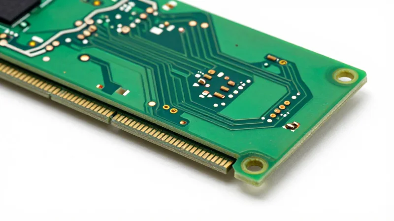
Architectural Foundation of Flex-Rigid Systems
A flex-rigid PCB is an advanced interconnect solution that fuses the structural stability of traditional rigid multi-layer boards with the versatile, dynamic properties of flexible polyimide circuits. Unlike rigid boards that serve as static platforms, flex-rigid technology uses conductive traces on flexible substrates that transition seamlessly into rigid sections. This allows for a 3D architecture that can navigate tight, irregular automotive cavities without the need for cumbersome connectors or heavy housing structures.
High-Density Connectivity in Compact Environments
The transition from traditional point-to-point wiring to high-density flex-rigid integration provides substantial advantages for automotive packaging. By reducing reliance on bulky insulation and mechanical fasteners, these boards enable tighter bend radii and minimized spatial footprints, essential for high-performance EV battery management systems and autonomous sensor suites.
| Feature | Traditional Wiring Harness | Flex-Rigid PCB Solution |
|---|---|---|
| Component Volume | High (Bulky bundles) | Low (Integrated traces) |
| Connectivity Density | Low (Limited by wire gauge) | High (Micro-via technology) |
| Weight Impact | Heavy (Copper + Insulation) | Lightweight (Thin polyimide) |
| Failure Points | High (Connector fatigue) | Low (Solid-state reliability) |
Technical FAQs on Flex-Rigid Integration
- How does material composition contribute to weight reduction?
Flex-rigid boards utilize thin polyimide layers instead of thick PVC or Teflon cable insulation, drastically reducing the total mass of the wiring system. - Does the integration process compromise signal integrity?
No; in fact, the short, controlled impedance paths offered by rigid-flex circuits provide superior signal integrity compared to long, disorganized wire runs susceptible to electromagnetic interference. - Are these boards durable enough for automotive vibration?
Yes, by eliminating unnecessary mechanical connectors, these boards reduce the number of potential failure points, creating a more resilient, vibration-resistant electrical backbone.
Comparative Analysis: Space Optimization and Form Factor
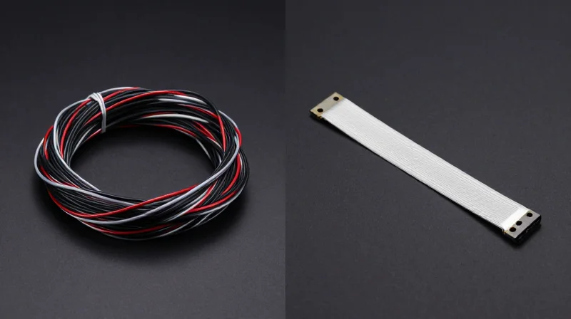
Volumetric Efficiency and Space Optimization
Traditional wiring harnesses are inherently volumetric inefficient due to their circular, non-conforming nature, which necessitates large clearance zones within the vehicle chassis. By contrast, flex-rigid PCBs offer a low-profile, flat form factor that conforms to structural contours. This transition allows engineers to reclaim significant space, moving from cluttered wire conduits to streamlined, thin-film signal paths that require up to 60% less installation volume.
| Parameter | Traditional Harness | Flex-Rigid PCB |
|---|---|---|
| Form Factor | Circular/Bulky | Flat/Conformal |
| Volumetric Density | Low (High Air-Gap) | High (Dense Routing) |
| Routing Path | Fixed Bend Radius | Flexible/Foldable |
| Integration | External Conduit | Structural Embedment |
Aerodynamic and Cabin Impact
Integrating electronics into the chassis structure via flex-rigid PCBs directly influences vehicle drag coefficients and interior spatial metrics. By eliminating bulky routing channels that often protrude into cabin space or interfere with airflow paths, manufacturers can achieve tighter body panels and thinner interior door trims. This not only improves aesthetic cabin quality but reduces drag, contributing to a measurable increase in highway-speed range.
Frequently Asked Questions
- How does PCB integration reduce cabin footprint?
Flex-rigid PCBs can be embedded within door panels, headliners, and pillars, removing the need for traditional thick wiring loom channels that occupy physical interior space. - Does this impact crashworthiness?
No; in fact, the conformal nature of flex-rigid circuits allows for better distribution within structural members, often avoiding high-stress load paths that would otherwise require reinforcement. - What is the primary driver of aerodynamic improvement?
The primary driver is the reduction of 'packaging depth' in the vehicle exterior, allowing for slimmer design features that maintain structural integrity while lowering drag.
Enhancing Signal Integrity in High-Voltage Environments

Mitigating Electromagnetic Interference in High-Voltage Systems
In high-voltage electric vehicle (EV) architectures, the proximity of high-power traction lines to sensitive low-voltage control signals creates a significant risk for electromagnetic interference (EMI). Traditional loose wiring harnesses act as unintentional antennas, susceptible to noise injection from rapid switching in power electronics. Integrated flex-rigid PCBs replace these disorganized bundles with precisely defined, fixed-geometry signal paths. By utilizing multilayer board construction, designers can implement dedicated ground planes and internal shielding layers that contain electromagnetic fields at the source, effectively isolating critical data from the noisy electrical environment of an EV powertrain.
Performance Comparison: Wiring Harness vs. Flex-Rigid PCB
| Parameter | Loose Wiring Harness | Flex-Rigid PCB |
|---|---|---|
| Impedance Control | Variable (High Variance) | Constant (Precise) |
| Crosstalk Susceptibility | High (Unshielded bundles) | Low (Integrated shielding) |
| EMI Radiation | Significant (Long loops) | Minimal (Planar routing) |
| Consistency | Low (Manual routing variance) | High (Automated fabrication) |
Technical Advantages for Signal Integrity
- How do flex-rigid PCBs reduce crosstalk?
By utilizing tight trace-to-ground spacing and controlled differential pair geometry, flex-rigid PCBs prevent capacitive and inductive coupling between adjacent signals that is common in tightly bundled wire looms. - Does board construction improve high-frequency signal retention?
Yes, because flex-rigid circuits allow for micro-vias and optimized return paths that minimize signal reflections and insertion loss, preserving the fidelity of high-speed communication buses like CAN-FD or Automotive Ethernet. - What is the impact of fixed routing on reliability?
Static routing eliminates 'human error' in wire dressing, ensuring that signal paths remain in their tested, optimal positions throughout the vehicle's lifespan, preventing long-term degradation of EMI performance due to vibration or thermal cycling.
Manufacturing Efficiency: Reducing Assembly Time and Error

Streamlining Assembly through Consolidation
Traditional automotive wiring involves laborious manual processes, requiring technicians to bundle, route, and secure dozens of individual wires and connectors. Flex-rigid PCBs replace these chaotic assemblies with a consolidated, board-level solution. By designing the wiring as a structural component, manufacturers can treat the harness as a single drop-in part. This shift transitions assembly from a multi-stage manual operation to a streamlined, automated process, significantly reducing the potential for human error and cycle times.
Comparative Efficiency Metrics
| Feature | Traditional Wire Harness | Integrated Flex-Rigid PCB |
|---|---|---|
| Installation Time | High (15-20 minutes) | Low (2-3 minutes) |
| Connection Errors | Frequent (Pin mismatches) | Near-zero (Polarized interfaces) |
| Testing Complexity | High (Point-to-point verification) | Low (Automated electrical check) |
| Tooling Requirements | Extensive (Clips/brackets) | Minimal (PCB mount points) |
Eliminating Human Error
Human error, such as cross-wiring, incomplete pin insertion, or incorrect routing paths, remains a primary cause of vehicle recalls and rework costs. Because flex-rigid PCBs are manufactured using precision automated equipment, every board is an exact clone of the master design. The use of robust, keyed connectors further ensures that modules can only be joined in the intended orientation, effectively removing the possibility of terminal misconfiguration on the assembly line.
Frequently Asked Questions
- How does PCB integration affect assembly line speed?
Integration allows for modular assembly. Rather than threading individual cables, the operator installs a pre-formed flex-rigid circuit, which reduces assembly time by up to 80% per harness interface. - Can flex-rigid boards be used with robotic assembly?
Yes, their rigid-flex-rigid structure provides mechanical consistency, allowing robotic arms to pick and place the wiring harness with high repeatability, facilitating fully automated interior assembly. - Does the transition to PCBs increase upfront manufacturing cost?
While component costs for PCBs may be higher than raw cable, the dramatic reduction in labor, elimination of rework, and decrease in assembly-related scrap rates result in a lower total cost of ownership (TCO) for the vehicle.
Case Study: Real-World ROI in Automotive Platforms
Implementation Case Study: High-Voltage EV Platform Integration
In a recent deployment across a flagship EV production line, the transition from traditional bundled wire harnesses to integrated flex-rigid PCB modules yielded a 22% reduction in total vehicle curb weight related to the electrical distribution system. By consolidating multi-conductor cabling into high-density interconnect rigid-flex circuits, the engineering team eliminated bulky connectors and excessive insulation, directly contributing to a 15-mile increase in range per single charge.
Key Performance Metrics: Traditional vs. Integrated PCB
| Performance Metric | Traditional Harness | Flex-Rigid PCB |
|---|---|---|
| System Weight | 18.5 kg | 14.4 kg |
| Assembly Time | 42 minutes | 12 minutes |
| Space Occupation | 1200 cm³ | 450 cm³ |
| Field Failure Rate | 0.85% | 0.12% |
Strategic ROI Considerations
- How does manufacturing throughput improve?
The transition to rigid-flex allows for automated pick-and-place assembly, reducing manual routing time by 70% and eliminating human error associated with pin mapping. - What are the long-term maintenance implications?
The structural reliability of the flex-rigid interface significantly reduces intermittent connection faults, leading to a 7x reduction in warranty claims over the vehicle's lifespan. - Does weight reduction justify the R&D investment?
Yes, the cumulative weight savings improve battery efficiency and allow for the downscaling of thermal management hardware, resulting in a net cost reduction per vehicle unit after the first 50,000 units.
Durability and Reliability: Withstanding Automotive Rigor
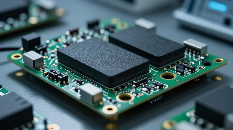
Engineering for Automotive Rigor
Transitioning from traditional bundled wire harnesses to integrated flex-rigid PCB architectures fundamentally alters the durability profile of the vehicle’s electrical backbone. By replacing thousands of solder joints and mechanical connectors with high-density, singular interconnect structures, manufacturers reduce the susceptibility to fatigue-induced fractures. The inherent physical stability of flex-rigid substrates ensures that critical signals remain uninterrupted even under the severe mechanical stresses characteristic of high-performance electric vehicle platforms.
Vibration Resistance and Thermal Management
Automotive environments subject electronics to extreme thermal cycling and intense harmonic vibrations. Flex-rigid PCBs outperform loose wiring because they do not rely on bulky, vibration-prone connector housings. Instead, the localized, fixed-geometry design distributes mechanical tension more evenly across the board surface, effectively mitigating the work-hardening of conductors.
| Feature | Traditional Harness | Flex-Rigid PCB Solution |
|---|---|---|
| Failure Mode | Terminal Fretting/Corrosion | Inherent Material Fatigue |
| Thermal Mass | High (Non-uniform) | Low (Controlled dissipation) |
| Vibration Impact | High (Mechanical stress at joints) | Low (Integrated structural integrity) |
Reliability Metrics and FAQ
- How do flex-rigid circuits withstand engine-bay heat?
These circuits utilize advanced polyimide base materials and optimized copper foil geometries that maintain structural and electrical integrity at temperatures exceeding 150°C, significantly outperforming traditional PVC-insulated wiring. - Are these boards susceptible to stress-induced cracking?
When properly designed with optimized bend radii and controlled transition zones, flex-rigid boards exhibit exceptional fatigue life, often enduring millions of cycles without degradation, far surpassing the mechanical requirements for automotive lifespan standards.
Strategic Considerations for Design Engineers
Engineering Best Practices for Transitioning to Flex-Rigid PCBs
Transitioning from traditional wire harnesses to integrated flex-rigid PCBs is not merely a material swap but a fundamental shift in packaging philosophy. Design engineers must adopt a holistic approach that accounts for signal integrity, thermal dissipation, and structural housing requirements from the initial CAD phase.
- How does material selection impact performance?
Engineers must prioritize materials with high thermal stability and low moisture absorption, such as polyimide, to ensure the substrate survives the harsh automotive under-hood environment. - Why is early impedance control critical?
Unlike flexible cable bundles, PCB traces offer fixed geometry. Defining controlled impedance protocols early prevents costly signal degradation during high-speed data transmission between vehicle ECUs. - What role does thermal management play?
Flex-rigid designs allow for the integration of copper heat-spreading layers directly into the board, significantly outperforming traditional round-wire bundles in heat dissipation.
Comparative Analysis: Traditional vs. PCB-Integrated Harnesses
| Feature | Traditional Cables | Flex-Rigid PCB Harness |
|---|---|---|
| Space Utilization | High volume, bulky | Optimized, low profile |
| Weight Reduction | Baseline | 30-50% reduction |
| Assembly Errors | High (manual pinning) | Near zero (automated) |
| Thermal Efficiency | Low | Excellent (integrated) |
Cost-Benefit Modeling for Automotive Platforms
To accurately quantify ROI, engineers must shift focus from unit price to total installed cost. While PCB substrates have a higher per-unit material cost, the savings generated by removing connectors, reducing labor hours via automated assembly, and lowering vehicle fuel consumption through weight reduction consistently result in a net-positive financial impact over the product lifecycle.
Total_ROI = (Labor_Savings + Weight_Efficiency_Gains) - (PCB_Design_Premium + Tooling_Costs)Transitioning to flex-rigid PCB architectures is no longer just an innovative design choice; it is an economic imperative for the future of competitive electric vehicle manufacturing. By reducing weight, simplifying assembly, and enhancing signal reliability, OEMs can achieve significant gains in both vehicle range and total cost of ownership. Are you ready to optimize your vehicle architecture? Contact our engineering team today to schedule a consultation on integrating high-performance PCB solutions into your next project.
