
As the automotive industry accelerates toward full autonomy and high-density electrification, the traditional wiring harness has become a critical bottleneck. Modern vehicles are essentially rolling data centers, requiring seamless connectivity that standard cables simply cannot sustain. Explore how the shift toward flex-rigid PCB architecture is solving the industry's biggest design challenges.
The Death of the Legacy Wiring Harness
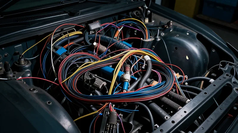
The Scaling Crisis of Legacy Architectures
For decades, the wiring harness has been the 'nervous system' of the automobile, but it is currently buckling under the weight of the software-defined vehicle transition. Legacy harnesses rely on massive bundles of copper wires that are manually routed, prone to assembly errors, and inherently bulky. In the context of Electric Vehicles, where every kilogram directly impacts battery range and performance, the persistent use of these legacy bundles represents an unacceptable engineering tax.
Performance Limitations of Traditional Wiring
- Signal Integrity
Traditional wires are susceptible to electromagnetic interference (EMI) and crosstalk, which significantly degrades high-speed data transmission required by autonomous driving sensors. - Thermal Management
Copper bundles create localized heat traps, requiring additional packaging space and cooling solutions that further add to vehicle mass. - Manufacturing Bottlenecks
The manual labor required to install and secure complex wiring harnesses makes them a leading cause of production line friction and potential failure points.
Comparative Analysis: Harness vs. Flex-Rigid PCB
| Feature | Legacy Wiring Harness | Flex-Rigid PCB Solution |
|---|---|---|
| Weight | High (Heavy Copper) | Low (Integrated Circuits) |
| Space Efficiency | Low (Bulky Bundles) | High (Thin, Conformal) |
| EMI Protection | Poor (Requires Shielding) | Excellent (Inherent Layering) |
| Installation | Manual/Slow | Automated/Precise |
Transitioning to flex-rigid PCBs allows engineers to collapse complex signal routing into thinner, lighter, and more reliable modular formats. By removing the physical inconsistency of hand-assembled harnesses, manufacturers can achieve tighter integration, improved signal throughput, and a substantial reduction in the vehicle's curb weight. The future of automotive connectivity is not in more copper, but in higher density, flexible signal management.
What are Flex-Rigid PCBs?
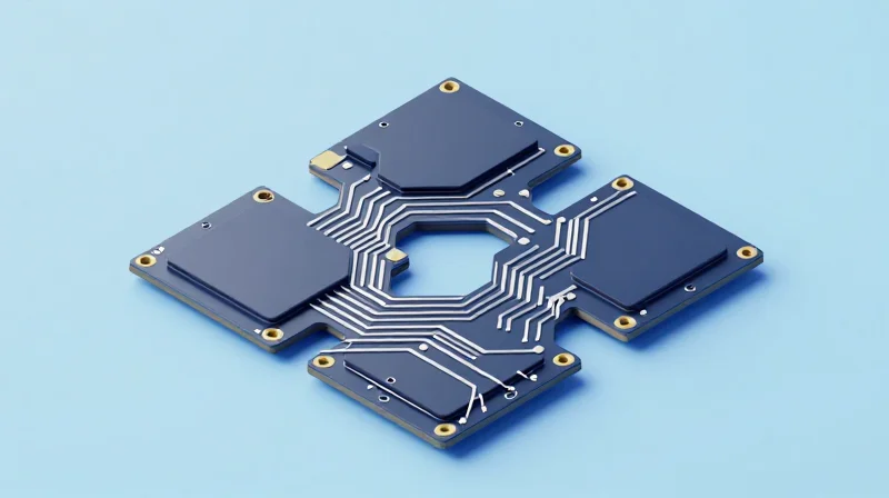
The Architecture of Flex-Rigid Integration
Flex-rigid PCBs represent a hybrid engineering approach, blending the robust structural support of multi-layer rigid boards with the high-degree-of-freedom mechanical properties of flexible circuits. At their core, these boards consist of multiple layers of conductive material that are interconnected via plated through-holes (PTHs). By transitioning from rigid sections—which house primary components like processors or power modules—to flexible zones that act as reliable, multi-axis interconnects, manufacturers can eliminate the need for bulky connectors and heavy, traditional cable harnesses.
Materials and Fabrication Benefits
The performance of these boards in demanding automotive environments is underpinned by material science. High-temperature resistant polyimide substrates ensure that the flexible portions can withstand constant thermal cycling and mechanical vibration without fatigue or signal degradation. This monolithic structure replaces mechanical fasteners and crimped connectors, which are common failure points in legacy automotive wiring.
| Feature | Traditional Harness | Flex-Rigid PCB |
|---|---|---|
| Mass | High (Copper cabling) | Low (Integrated traces) |
| Reliability | Connector-dependent | Solid-state interconnection |
| Space Efficiency | Low (Requires routing clearance) | High (3D form factor) |
| Signal Integrity | Susceptible to EMI | High (Controlled impedance) |
Key Advantages for EV Platforms
- Why do flex-rigid boards improve reliability in EVs?
By eliminating traditional manual wiring harnesses and connectors, these boards reduce the number of potential points of failure, which is critical for safety-critical EV electronic systems. - How does weight reduction impact vehicle performance?
Every gram removed from the vehicle architecture directly correlates to improved battery range and energy efficiency, a primary metric for modern electric mobility. - Are these boards suitable for high-vibration environments?
Yes, because the flexible polyimide layers distribute mechanical stress more uniformly than rigid cable bundles, preventing lead-in fractures during vehicle operation.
Space Efficiency: Rethinking Vehicle Interior Packaging
The Spatial Paradigm Shift in Vehicle Interior Packaging
In the transition toward software-defined vehicles, the interior environment has become the primary battleground for space optimization. Traditional wiring harnesses act as a rigid 'spaghetti' of copper that consumes significant volumetric space, often necessitating larger pillars, thicker dashboards, and compromised seating ergonomics. By migrating to flex-rigid PCBs, automotive engineers can replace bulky bundles with thin, foldable, and multi-planar electronic substrates that conform to the vehicle chassis, allowing for smaller sensor housings and ultra-compact module placement.
Comparative Efficiency of Interconnect Technologies
| Feature | Traditional Harness | Flex-Rigid PCB |
|---|---|---|
| Volume Footprint | High (bulky bundles) | Low (ultra-thin profile) |
| Weight Reduction | Minimal | 30-50% lighter |
| Component Density | Limited by connector size | High-density integration |
| Packaging Flexibility | Requires large bend radii | Dynamic folding and shaping |
Enabling Compact Sensor and Actuator Integration
Flex-rigid technology empowers designers to push components into previously inaccessible zones, such as tight door panels or integrated roof modules. Because these circuits can bend around structural members, the need for intermediary connectors is significantly reduced. This reduction in connector counts not only saves physical space but also improves signal integrity, reducing the latency issues associated with long, coiled wire runs in modern EV sensor arrays.
Frequently Asked Questions
- How do flex-rigid PCBs reduce cabin clutter?
They replace bulky, round wire bundles with flat, multi-layer circuits that can be routed directly inside vehicle panels, removing the need for cable channels. - Can flex-rigid circuits handle vibration in vehicle doors?
Yes, they provide superior mechanical reliability compared to traditional solder-jointed harnesses, as the flexible polyimide layers absorb stress better than rigid copper wires. - Does this technology impact the overall weight of the EV?
Significantly. Replacing copper-heavy harnesses with lighter flexible circuits contributes to improved range by reducing the overall curb weight of the vehicle electronic system.
Enhancing Reliability in Autonomous Systems

Mitigating Failure Points in Autonomous Architectures
In autonomous driving systems, reliability is defined by the integrity of the data stream between sensors, compute modules, and actuators. Traditional wire harnesses rely on numerous crimped, soldered, or connector-based terminations, each representing a potential point of failure due to oxidation, thermal cycling, or contact degradation. Flex-rigid PCBs replace these variable interfaces with monolithic, high-density interconnections, ensuring a constant, low-impedance signal path that is immune to the common mechanical faults associated with mass-produced wiring looms.
Mechanical Resilience and Vibration Damping
Autonomous vehicles operate in environments where constant micro-vibrations can lead to 'fretting corrosion' in traditional connectors. Flex-rigid circuits distribute stress across the structural substrate rather than concentrating it at solder joints. Because the flexible polyimide layers are integrated directly into the rigid component, the assembly maintains electrical connectivity even under significant physical deformation and thermal shock, which is critical for the stability of LiDAR and ADAS camera systems.
| Feature | Traditional Wire Harness | Flex-Rigid PCB |
|---|---|---|
| Interconnect Density | Low - prone to manual error | High - machine-precision traces |
| Vibration Impact | High risk of fretting/loosening | Integrated structural dampening |
| Signal Integrity | Susceptible to EMI/crosstalk | Shielded, controlled impedance |
| Failure Points | Crimp/connector interface failure | Minimal (monolithic design) |
Reliability Metrics: Frequently Asked Questions
- How do flex-rigid boards handle high-temperature environments?
By utilizing high-Tg (glass transition temperature) polyimide films, these circuits maintain their dielectric properties and mechanical stability far beyond the limitations of standard PVC or cross-linked polyethylene wiring jackets. - Does the reduction of connectors affect repairability?
While traditional harnesses are individually modular, the move toward autonomous platforms prioritizes 'replace-as-a-module' strategies, where the inherent durability of the PCB-based architecture significantly reduces the need for frequent field repairs. - Why are PCBs safer for high-speed data transmission?
Flex-rigid boards provide precise control over trace geometry and spacing, which minimizes signal reflections and electromagnetic interference—factors that are impossible to control consistently in bundled, manual wire harnesses.
Impact on EV Battery Management Systems (BMS)
Precision Thermal Management and Sensing
Traditional wiring harnesses often suffer from bulky connector housings and complex cable routing that impede thermal monitoring accuracy. By replacing bulky wires with flex-rigid PCBs, manufacturers can embed temperature sensors directly into the flex zones between battery cells. This allows for near-instantaneous thermal data acquisition, enabling the Battery Management System (BMS) to execute more precise cooling cycles and mitigate the risk of thermal runaway.
Performance Comparison: Harnesses vs. Flex-Rigid PCBs
| Feature | Traditional Wire Harness | Flex-Rigid PCB |
|---|---|---|
| Signal Integrity | Susceptible to EMI/crosstalk | Shielded, controlled impedance |
| Sensor Density | Limited by physical connector size | High integration density |
| Thermal Response | Slow due to bulk/distance | High-speed, direct contact |
| Reliability | Prone to crimp failure | Monolithic, vibration-resistant |
Optimizing Power Distribution
In the high-voltage environment of modern EV battery packs, power distribution efficiency is critical. Flex-rigid circuits provide high-current capacity in a low-profile form factor, minimizing resistive losses across the BMS assembly. By eliminating redundant connectors and complex solder joints, these PCBs reduce the impedance paths between the battery management ICs and the cell monitoring units, leading to faster data transmission and improved balancing performance.
Frequently Asked Questions
- How do flex-rigid PCBs improve safety in a crash?
Unlike wire harnesses which can fray or disconnect at crimp points, flex-rigid PCBs act as a unified, flexible structure that deforms with the pack, significantly reducing the probability of intermittent connection failures during high-G impacts. - Does the transition to PCB-based BMS increase manufacturing costs?
While component costs for flex-rigid substrates may be higher than raw wire, the total cost of ownership is reduced through automated assembly, lower labor requirements for installation, and reduced warranty claims due to connector failures.
Thermal Management and Weight Reduction

The Impact of Weight Reduction on Range Efficiency
In the transition from traditional wire harnesses to flex-rigid PCBs, the most immediate benefit is a drastic reduction in copper and insulation mass. Traditional looms involve heavy bundles of discrete wires, each requiring insulation, shielding, and mounting hardware. By integrating these electrical paths into thin, flexible layers, OEMs can shed significant kilograms from the chassis. This reduction in vehicle curb weight directly translates to a linear increase in efficiency, allowing for either extended range from the same battery capacity or the use of smaller, lighter battery packs that further improve vehicle dynamics.
Optimizing Thermal Dissipation in High-Density Assemblies
Traditional wire harnesses act as thermal insulators, trapping heat within bundles and causing localized hotspots that degrade insulation over time. Flex-rigid PCBs flip this paradigm. With their large copper surface areas and ability to be bonded directly to heat-conducting substrates or aluminum frames, they provide a continuous thermal path for heat dissipation. This ability to integrate thermal management directly into the circuit design prevents the heat buildup commonly found in high-current EV power distribution modules.
| Metric | Traditional Wire Harness | Flex-Rigid PCB |
|---|---|---|
| Mass Density | High | Low |
| Thermal Conductivity | Poor (Insulated) | High (Copper Planes) |
| Volume Utilization | Bulky/Circular | Flat/Conformal |
| Installation Labor | High (Manual) | Low (Automated) |
Frequently Asked Questions
- How does weight reduction correlate to range?
Every 100kg of mass reduced typically yields a 2-3% increase in total range for an electric vehicle, making lightweight flex-rigid alternatives essential for long-range performance. - Do PCBs require active cooling systems?
Unlike wire harnesses which rely on airflow, flex-rigid PCBs can be mounted to chassis heat sinks, allowing the entire vehicle frame to act as a radiator for the electronics. - Is the material cost higher for flex-rigid circuits?
While unit cost per board is higher, total system cost is often lower when considering the reduced labor, decreased weight penalties, and eliminated need for secondary thermal management hardware.
Navigating Manufacturing Challenges and Scalability
Overcoming the Transition from Manual Assembly to Automated PCB Integration
Moving away from traditional manual wire loom routing to robotic assembly of flex-rigid PCBs is the most significant hurdle for automotive OEMs. While harness manufacturing is labor-intensive and error-prone, PCB integration requires high-precision surface-mount technology (SMT) lines. Success depends on redesigning vehicle chassis interfaces to accommodate board-level connectivity, which eliminates the variability associated with human-installed harnesses.
Comparative Efficiency: Harnesses vs. Flex-Rigid PCB Manufacturing
| Metric | Traditional Wire Harness | Flex-Rigid PCB Solution |
|---|---|---|
| Assembly Process | Manual/Semi-automated | Fully Automated (SMT/Robotic) |
| Component Volume | High (Bulky/Heavy) | Low (Slim/Integrated) |
| Quality Control | Visual/Physical Inspection | Automated Optical/X-ray Inspection |
| Scalability Potential | Limited by Labor Costs | High (Throughput-based) |
Scalability and Supply Chain Considerations
To reach mass-market volumes, manufacturers must address the upfront investment costs of advanced fabrication tooling. The shift requires a transition from tier-two harness vendors to electronics assembly partners capable of handling high-layer-count rigid-flex substrates at automotive-grade volumes. Economies of scale are achieved not through volume alone, but through the reduction of assembly steps and the elimination of complex connectors that frequently serve as failure points.
Frequently Asked Questions on Scaling PCB Adoption
- Does the higher unit cost of PCBs negate the weight-saving benefits?
No; while individual component costs are higher, the total cost of ownership is reduced by lower installation labor, less downtime for repairs, and significant weight savings that increase EV range and vehicle efficiency. - Are existing assembly lines compatible with flex-rigid PCB integration?
Most traditional assembly lines are not compatible; they require retooling for automated pick-and-place systems and precise robotic jigs, necessitating a dedicated capital expenditure plan for full-scale EV production. - How do we ensure long-term reliability in high-vibration environments?
Flex-rigid boards offer superior reliability because they move away from mechanical crimps and bulky connectors, utilizing solder-based or high-pressure interconnects that minimize stress points during thermal cycling.
Future Outlook: The Software-Defined Vehicle
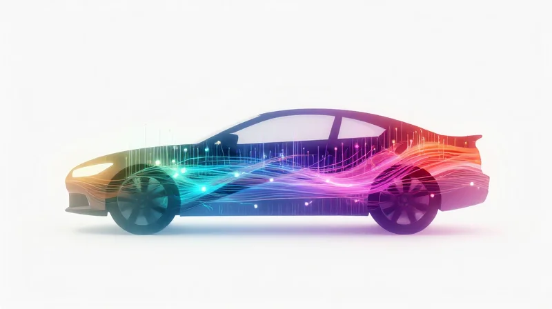
The Shift to Software-Defined Architecture
As the automotive industry pivots toward the software-defined vehicle (SDV), the hardware backbone must evolve beyond traditional point-to-point wiring. Future vehicle platforms are shifting toward zonal architectures, where high-bandwidth, low-latency communication is critical for AI-driven driver assistance systems and vehicle-to-everything (V2X) protocols. Flex-rigid PCBs serve as the essential hardware foundation for these architectures, enabling modular, high-density signal transmission that legacy wire harnesses simply cannot accommodate.
Comparative Analysis: Connectivity Solutions
| Feature | Traditional Wire Harness | Flex-Rigid PCB Solution |
|---|---|---|
| Data Bandwidth | Limited / EMI prone | High-speed / Shielded |
| Space Efficiency | Bulky looms | High-density integration |
| AI/V2X Readiness | Low adaptability | Highly programmable |
| Failure Points | High (Connectors) | Low (Integrated traces) |
Facilitating AI and V2X Integration
Real-time AI processing at the edge requires extreme reliability in data transmission between sensors and compute modules. Flex-rigid PCBs allow for direct integration of high-frequency components onto a single board, reducing signal attenuation and crosstalk. Furthermore, as V2X communication requires the vehicle to act as a node in a massive network, the thermal stability and signal integrity provided by flex-rigid technology ensure continuous connectivity under dynamic road conditions.
Frequently Asked Questions
- Why are flex-rigid PCBs better for V2X?
They minimize signal loss and electromagnetic interference, which is vital for the sub-millisecond latency requirements of V2X communication. - How does this support future software updates?
Modular board designs allow for easier hardware upgrades and sensor additions, providing the scalability needed for long-term software-defined vehicle life cycles. - Can flex-rigid boards handle the power needs of AI compute units?
Yes, their multilayer copper structures offer superior power distribution density compared to standard wiring, effectively managing the high current demands of autonomous computing hardware.
The transition to flex-rigid PCB technology is not just an incremental improvement; it is the backbone of the next automotive revolution. By reducing weight, increasing reliability, and optimizing space, engineers can finally unlock the full potential of EV and autonomous technology. Contact our engineering team today to see how we can integrate advanced circuit solutions into your next vehicle platform.
