
As the demand for long-term continuous ECG monitoring grows, the reliability of flexible printed circuits (FPCs) becomes paramount. Engineers must balance ultra-thin profiles with the mechanical rigor required for millions of stress cycles. This guide outlines the essential Design for Manufacturing (DFM) principles to prevent trace failure and ensure clinical-grade signal performance in wearable devices.
Understanding the Mechanical Constraints of Ultra-Thin Flex
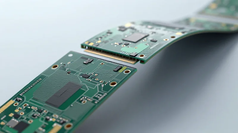
The Neutral Axis Principle in Dynamic Flex
To achieve high-flex life, the copper traces must be positioned at the mechanical neutral axis of the laminate stack. As a PCB bends, the material on the outside of the curve experiences tensile stress, while the material on the inside faces compressive stress. By balancing the thickness of the top and bottom coverlays and adhesive layers, designers can ensure the conductive copper remains in the zero-strain zone, effectively eliminating the risk of fatigue-induced fractures.
Material Performance Comparison
| Material Type | Typical Thickness | Flex Durability | Primary Failure Mode |
|---|---|---|---|
| Rolled Annealed (RA) Copper | 12 - 18 µm | Excellent | Grain Boundary Migration |
| Electro-Deposited (ED) Copper | 18 - 35 µm | Poor | Brittle Cracking |
| Polyimide Film | 12 - 25 µm | Superior | Thermal Delamination |
Design Constraints and FAQ
- Why is RA copper mandatory for ECG wearables?
Unlike ED copper which has a vertical grain structure prone to stress cracking, Rolled Annealed copper features a horizontal grain structure that allows it to deform elastically during repeated bending cycles without propagating micro-cracks. - What is the minimum bend radius for dynamic flex?
As a rule of thumb, the bend radius should be at least 10 to 20 times the total thickness of the flexible circuit to avoid exceeding the yield strength of the copper conductors. - How does coverlay choice affect mechanical fatigue?
Using a flexible acrylic adhesive or a low-modulus coverlay prevents the rigidification of the trace area, which minimizes stress concentrations at the transition point between the flexible and rigid sections.
Copper Plating and Grain Structure Optimization
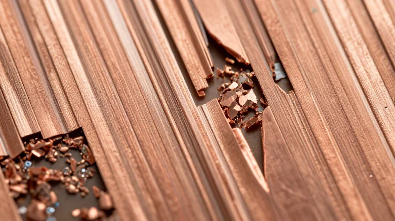
Electro-deposited (ED) vs. Rolled-Annealed (RA) Copper
The fatigue resistance of a flexible PCB is fundamentally dictated by the grain morphology of the copper foil. In high-flex ECG wearables, designers must avoid standard ED copper. Electro-deposited copper exhibits a columnar, vertical grain structure that is inherently brittle under cyclic loading, making it prone to stress fractures. Conversely, Rolled-Annealed (RA) copper undergoes mechanical rolling and heat treatment, resulting in elongated, horizontal grains that allow the metal to flex and redistribute stress without initiating cracks.
| Feature | ED Copper | RA Copper |
|---|---|---|
| Grain Structure | Columnar/Vertical | Elongated/Horizontal |
| Flex Performance | Low | High |
| Typical Application | Rigid PCBs | Dynamic Flex Wearables |
| Fatigue Tolerance | Poor | Excellent |
Plating Optimization for Durability
Selecting the base copper foil is only half the battle; the plating process used for through-holes and pads must also be optimized for flexibility. Standard electrolytic plating often builds up rigid copper in vias, creating a 'stress concentration point' where the flexible circuit will inevitably fail during repetitive ECG monitoring. Designers should specify ductility-enhanced plating baths and limit copper thickness within the flex areas to maintain a neutral mechanical axis.
Key DFM Considerations for Copper Reliability
- Can I use ED copper for static flex designs?
Yes, ED copper is sufficient for 'flex-to-install' applications where the PCB is bent only once. However, it should never be used for continuous motion applications. - How does copper thickness affect the bending radius?
Thinner copper foils (e.g., 1/3 oz or 1/2 oz) significantly decrease the neutral axis stress, allowing for a much tighter bend radius without exceeding the yield point of the material. - Should I avoid plating in flex regions?
Whenever possible, keep plated through-holes out of the dynamic bending area. If required, use 'filleted' pads to distribute mechanical strain more evenly across the copper surface.
Advanced Trace Routing Strategies for Flex Circuits
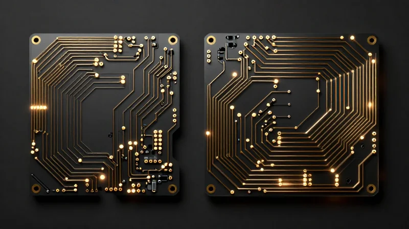
Geometric Optimization: From Right Angles to Arcs
In high-flex ECG wearables, traditional 90-degree trace corners act as localized stress risers, significantly increasing the probability of copper fatigue and fracturing during repetitive bending. To maximize lifecycle, designers must transition to rounded or arc-based routing, which allows for the even distribution of mechanical loads along the trace path.
| Feature | Right-Angle Routing | Arc/Rounded Routing |
|---|---|---|
| Stress Distribution | High concentration at vertices | Uniform dissipation |
| Fatigue Resistance | Low (High cracking risk) | High (Excellent longevity) |
| Manufacturing | Simpler CAM processing | Requires controlled radius |
Best Practices for Trace Layout
- Maintain Arc Radii
Ensure trace bends maintain a minimum radius of at least 3x the trace width to avoid work-hardening the copper during dynamic operation. - Staggered Trace Patterns
Avoid stacking traces directly on top of each other across multiple layers; stagger them to create a neutral-axis balance that reduces stress in the Z-axis. - Tapered Interconnects
Use tapered transitions (teardrops) where traces meet pads to eliminate abrupt changes in cross-sectional geometry, which prevents peeling and delamination.
Advanced Routing Strategies FAQ
- Why should I avoid 'I-Beam' construction?
Stacking traces directly on top of each other creates an I-beam effect that significantly increases stiffness and decreases flexibility, leading to premature substrate cracking. - What is the optimal trace width for high-flex zones?
Use the narrowest traces feasible for your current and signal integrity requirements; thinner traces exhibit greater compliance and lower bending stress compared to wider, stiffer copper paths.
Selecting the Right Coverlay and Stiffener Materials
The long-term reliability of ECG wearables depends on the synergistic relationship between coverlay adhesives and substrate stiffness. Mismatched Coefficients of Thermal Expansion (CTE) between the flexible base and rigid stiffeners frequently lead to interface stress, manifesting as micro-cracking or localized delamination during repeated dynamic motion. For high-flex applications, engineers must prioritize high-elongation acrylic adhesives and polyimide-based coverlays that mirror the mechanical properties of the base laminate.
Comparative Analysis of Stiffener Materials
| Material Type | Flexibility | CTE Match | Best Use Case |
|---|---|---|---|
| Polyimide (PI) | High | Excellent | Component support in bending zones |
| FR-4 | None | Low | Connector areas and rigid housings |
| Stainless Steel | Medium | Moderate | EMI shielding and thermal dissipation |
Adhesive Selection Guidelines
Adhesives are the weakest link in a flex circuit. For continuous-wear ECG devices, acrylic-based adhesives are standard due to their high peel strength and inherent flexibility. However, for extreme dynamic environments, consider epoxy-based adhesives if thermal requirements are stringent, provided they are formulated for high-elongation to prevent brittle failure.
Design FAQ: Materials and Reliability
- Why is CTE matching critical for ECG patches?
Continuous movement in a wearable causes localized heat buildup; if materials expand at different rates, the interface shear forces will cause the coverlay to peel away from the copper traces. - When should I avoid using FR-4 stiffeners?
Avoid FR-4 in any area subject to repeated bending; use PI or thin stainless steel instead to ensure the transition from rigid to flexible remains gradual and stress-relieved. - How does coverlay thickness affect flex life?
Thinner coverlays reduce the neutral axis shift during bending, significantly increasing the cycle life compared to thicker, more rigid protective layers.
Neutral Axis Management in Multi-Layer Designs
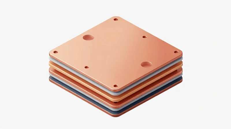
Principles of Symmetrical Stacking
The neutral axis represents the plane within a bent material where internal stress—compression on the inside radius and tension on the outside—is theoretically zero. To maximize flex life in ECG wearable PCBs, circuit layers must be balanced around this central axis to prevent cyclic work-hardening of copper conductors.
| Stacking Strategy | Effect on Neutral Axis | Recommended Application |
|---|---|---|
| Symmetrical Stack | Balanced stress across layers | Continuous dynamic flexing |
| Asymmetrical Stack | Shifts stress to outer layers | Static or limited flex applications |
Engineering the Neutral Axis
For multi-layer flexible circuits, utilize 'bookbinder' or 'ladder' construction techniques. By placing the most critical signal traces as close to the mechanical center of the laminate stack as possible, you effectively isolate them from the tensile forces that cause fatigue-related fractures during the frequent bending inherent to ECG monitoring.
- How do I calculate the neutral axis?
The axis is determined by the cross-sectional area and the Young's modulus of all materials in the stack. Aim for material symmetry above and below the center line. - Why avoid single-layer copper on thick laminates?
Single-layer copper on a thick substrate puts the conductor at maximum distance from the neutral axis, leading to premature tensile failure during radius bends. - What is the 'Bookbinder' design method?
It involves staggering the copper layers in the bend region, essentially using a nested design to keep individual conductors within the neutral zone.
/* Design Rule Check (DRC) Parameters for Flex */
MAX_BEND_RADIUS_RATIO = 20; // 20x material thickness
NEUTRAL_AXIS_VARIANCE_TOLERANCE = 0.05; // mm
COPPER_BALANCE_THRESHOLD = 0.90; // Symmetrical density requirement
Minimizing Stress at Component Interconnects
Mitigating Stress at Rigid-Flex Interfaces
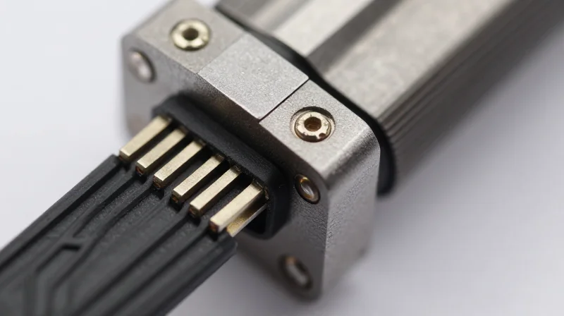
The rigid-to-flex interface is the most common point of failure in wearable ECG devices. Solder joints, being inherently brittle, cannot accommodate the mechanical strain induced by repetitive bending and twisting. Effective DFM requires a transition strategy that isolates these vulnerable interconnections from external mechanical stress.
Design Guidelines for Transition Zones
- Strain Relief Padding
Utilize soft, high-elongation epoxy or silicone beads at the transition edge to absorb mechanical energy and prevent it from reaching the solder interface. - Teardrop Filleting
Apply teardrop pads to all surface mount components located near the flex-rigid interface to reduce stress concentrations at the trace-pad neck. - Coverlay Setback
Ensure that the coverlay does not terminate exactly at the transition point; ending it slightly back from the rigid edge prevents a 'hinge effect' that concentrates stress. - Stiffener Integration
Extend stiffeners slightly into the flex area to support the rigid components, ensuring the bend radius does not begin immediately at the solder joint.
Comparison of Stress Management Techniques
| Strategy | Primary Function | Reliability Impact |
|---|---|---|
| Teardropping | Stress Distribution | Reduces micro-cracking risk at trace necks. |
| Epoxy Potting | Vibration/Flex Damping | Significantly limits joint displacement. |
| Stiffener Overlap | Bending Prevention | Forces the bend radius away from solder joints. |
Frequently Asked Questions
- How far should the stiffener extend into the flex area?
For maximum durability, extend the stiffener at least 1.0mm to 2.0mm beyond the rigid-flex boundary to prevent acute bending right at the interface. - Is SMT component orientation important?
Yes; orient long, rectangular components with their longest axis parallel to the bending direction whenever possible to minimize the torque applied to individual solder joints.
Verification and Reliability Testing Protocols
Cyclic Bend Testing Methodologies
To validate the fatigue life of your ECG wearable, you must subject representative samples to accelerated cyclic bend testing. This process simulates the repeated mechanical stress the device will encounter during daily use. It is critical to define the minimum bend radius (MBR) and the required number of cycles based on the intended service life of the wearable, typically ensuring performance persists through at least 100,000 bending cycles without signal degradation or copper micro-cracking.
Environmental Stress Screening
Because ECG wearables undergo thermal expansion during operation and environmental exposure, thermal cycling is non-negotiable. By exposing the PCB to rapid temperature fluctuations, you can identify failures in interlayer adhesion and potential CTE-mismatch related cracking at component solder joints.
| Test Type | Primary Goal | Pass/Fail Metric |
|---|---|---|
| Cyclic Bend Test | Fatigue Resistance | Resistance shift < 10% |
| Thermal Cycling | CTE Mismatch Stress | No delamination or open circuits |
| Highly Accelerated Life Testing (HALT) | Design Margin Limits | Time to failure beyond expected life |
Verification FAQ
- How does moisture absorption affect high-flex PCBs?
Polyimide, the standard substrate, is hygroscopic. Excess moisture can lead to delamination during soldering or high-temperature operation, so pre-baking panels before testing is standard practice. - Why is cross-sectional analysis required post-testing?
Visual inspection is insufficient for detecting micro-cracks in copper plating. Micro-sectioning allows engineers to inspect the barrel of the vias and the trace cross-sections for fatigue induced fatigue fractures. - Should testing be performed on production PCBs?
Always perform reliability testing on prototype coupons that mirror the actual stack-up and routing density of the production unit to ensure the DFM guidelines remain valid across the final assembly.
Achieving millions of cycles in ECG wearables is not just about design, but about precision execution in every layer of the stack-up. By adhering to these DFM best practices, you can minimize field failures and ensure consistent clinical data. Contact our engineering team today to review your next wearable design project and ensure it is ready for high-volume, long-life production.
