
As the automotive industry accelerates toward Level 5 autonomy, the demand for precision imaging has never been higher. Yet, the traditional PCB architectures powering current camera modules are hitting a physical ceiling. This article explores why the transition to miniaturized, high-performance substrates is the critical missing link in achieving reliable sensor fusion for the next generation of safe, autonomous vehicles.
The Evolution of Automotive Imaging Hardware
From Analog Pioneers to Digital Vision
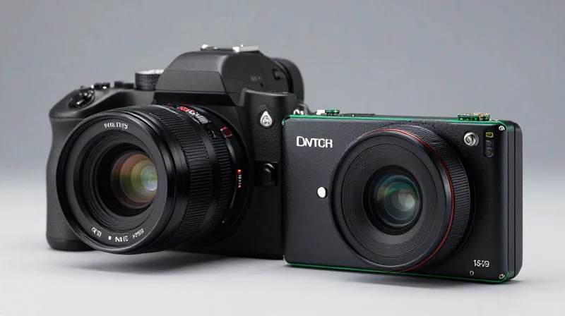
The initial wave of automotive imaging was characterized by bulky, analog sensors relegated exclusively to basic reversing assistance. These early systems functioned as simple visual aids, lacking the computational power to process metadata or identify hazards autonomously. As the industry pivoted toward safety-critical ADAS (Advanced Driver Assistance Systems), the architecture shifted from analog to high-definition digital signals, enabling real-time image processing and object detection.
Technological Milestones in Hardware Architecture
| Era | Hardware Focus | Primary Application |
|---|---|---|
| 1st Gen (2000-2010) | Analog CMOS Sensors | Basic Backup Parking |
| 2nd Gen (2010-2018) | Digital LVDS + Standard PCBs | Lane Keep, AEB |
| 3rd Gen (2018-Present) | Miniaturized SoCs + ISP Integration | Level 3+ Autonomy |
The Shift Toward Miniaturization
Modern automotive design requires high-density hardware capable of fitting into increasingly compact vehicle surfaces, such as door handles or side mirrors. The transition from massive, traditional PCB layouts to System-on-Chip (SoC) integration represents a paradigm shift, allowing OEMs to achieve higher performance within a significantly smaller thermal and physical footprint. This architectural consolidation is crucial for reducing latency and power consumption in edge-AI imaging.
Frequently Asked Questions
- Why was the shift from analog to digital critical?
Digital architectures allow for high-speed transmission and direct integration with deep-learning inference engines, which is impossible with analog legacy systems. - What drives the need for miniaturized camera solutions?
Miniaturization is driven by the need for aesthetic integration, improved aerodynamic efficiency, and the necessity to pack multiple sensor clusters into constrained vehicle locations.
Limitations of Legacy PCB Architectures
The Physical and Thermal Bottlenecks of Rigid PCBs
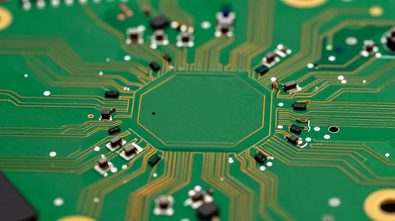
As automotive imaging systems transition toward 8MP resolution and beyond, legacy PCB designs are struggling to keep pace. Rigid boards occupy significant volumetric space, which is increasingly restricted within sleek, aerodynamic vehicle housings. Furthermore, the heat density generated by advanced Image Signal Processors (ISPs) often exceeds the passive cooling capabilities of standard FR4 substrates, leading to performance throttling and accelerated hardware degradation.
Comparative Analysis: Traditional vs. Emerging Constraints
| Challenge | Legacy PCB Impact | Imaging Performance Consequence |
|---|---|---|
| Spatial Footprint | High volume usage | Limits camera integration density |
| Thermal Dissipation | Low thermal conductivity | ISPs overheat under heavy AI load |
| Signal Integrity | High parasitic capacitance | Data loss at multi-gigabit speeds |
Addressing Signal Integrity and Reliability
Automotive environments are notorious for Electromagnetic Interference (EMI) and harsh vibrations. Legacy multi-layer rigid boards often rely on bulky connector systems to manage complex data paths. These connectors represent weak points in the mechanical chain, prone to fretting corrosion and signal degradation under constant road stress, which is unacceptable for safety-critical Advanced Driver Assistance Systems (ADAS).
Frequently Asked Questions
- Why is FR4 material considered limiting for modern automotive cameras?
FR4, while cost-effective, suffers from poor thermal management properties and insufficient dielectric performance at the high frequencies required for uncompressed raw image data transmission. - How do rigid architectures affect camera installation?
The stiffness of rigid PCBs limits the ability to mold hardware into curved vehicle surfaces or compact side-mirror housings, often forcing manufacturers to compromise on camera placement and field-of-view. - Do traditional boards introduce latency?
Yes; complex routing on large-format PCBs can introduce parasitic impedance, necessitating more robust signal conditioning circuitry which adds both physical bulk and increased signal path latency.
The Miniaturization Mandate: Why Size Matters
The Miniaturization Mandate: Why Size Matters
As vehicles evolve into mobile computing platforms, the spatial budget for vision systems is shrinking while performance demands are skyrocketing. The industry shift toward miniaturization is not merely an aesthetic preference; it is a critical engineering requirement dictated by the need for seamless sensor integration into sleek, aerodynamic body panels and the necessity to reduce the total surface area of complex imaging assemblies.
Engineering Constraints and Design Freedom
Miniaturized camera solutions leverage advanced packaging techniques such as System-in-Package (SiP) and flexible hybrid electronics to achieve a smaller form factor. By reducing the PCB footprint, engineers can house high-resolution sensors in tighter housings, minimizing the visual impact on the vehicle exterior and allowing for placement in non-traditional locations, such as mirror arms or integrated into lighting clusters.
| Feature | Traditional PCB Architecture | Next-Gen Miniaturized Solutions |
|---|---|---|
| Form Factor | Large, bulky, rigid | Compact, integrated, flexible |
| Integration | External mount required | Seamless flush mounting |
| Weight | Higher due to support structures | Significantly reduced |
| Aerodynamic Impact | High drag profile | Minimal to zero drag |
Key Considerations for Miniaturized Imaging
- How does miniaturization impact thermal management?
Smaller modules have less surface area for heat dissipation, necessitating advanced thermally conductive materials and optimized layout design to prevent sensor throttling. - Is signal integrity compromised by smaller boards?
Miniaturized systems often utilize high-density interconnects and shielded components to maintain signal integrity despite the proximity of high-speed data paths. - What role does lens technology play?
Miniaturization requires high-precision wafer-level optics that can deliver image clarity comparable to traditional glass lenses within a fraction of the depth.
Ultimately, the transition to smaller imaging modules empowers automotive designers to maintain vehicle aesthetics without compromising the data throughput necessary for L3 and L4 autonomous driving capabilities.
Advanced Substrate Materials and Performance Gains
Redefining Substrate Performance: Beyond FR-4
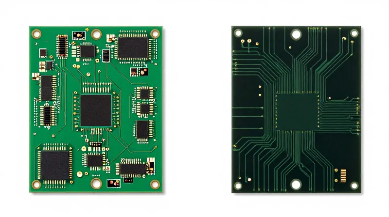
As automotive imaging demands transition toward high-frame-rate 4K sensors, traditional FR-4 glass-epoxy substrates have become a bottleneck. The dielectric loss and thermal impedance of standard PCBs result in signal attenuation and degradation, which complicates long-distance data transmission. Next-generation camera solutions leverage advanced substrates like Polytetrafluoroethylene (PTFE)-based laminates, ceramic-filled materials, and flexible polyimides to maintain signal integrity while shrinking the physical footprint of the camera module.
| Material Type | Thermal Conductivity | High-Frequency Performance | Primary Application |
|---|---|---|---|
| Standard FR-4 | Low | Poor | Basic sensors |
| PTFE/Ceramic | Moderate | Excellent | High-speed data |
| Flexible Polyimide | Low | Good | Space-constrained housing |
| Metal-Core PCB | High | Moderate | Thermal dissipation |
Thermal Management and Signal Integrity
Thermal management is no longer an auxiliary concern; it is a fundamental design requirement for AI-integrated automotive cameras. Ceramic substrates offer superior thermal expansion matching and heat dissipation compared to organic substrates. By utilizing Alumina or Aluminum Nitride, engineers can place image signal processors (ISPs) directly on the substrate, reducing the path length for heat conduction and mitigating thermal noise in the CMOS sensor, which directly improves low-light image quality.
Frequently Asked Questions on Substrate Advancements
- Why is PTFE preferred for high-frequency imaging?
PTFE laminates exhibit a stable dielectric constant across varying temperatures and frequencies, which prevents signal jitter and loss in high-speed LVDS or GMSL transmission lines. - How do flexible circuits assist in miniaturization?
Flexible circuits allow for three-dimensional folding within the tight confines of a camera housing, eliminating the need for bulky connectors and rigid-to-flexible transition points. - What is the primary benefit of ceramic substrates?
They provide high thermal conductivity and excellent mechanical stability, preventing board warping that can cause misalignment of the lens assembly during high-vibration automotive operations.
Sensor Fusion: Bridging Hardware and Software
The Architecture of Real-Time Synchronization
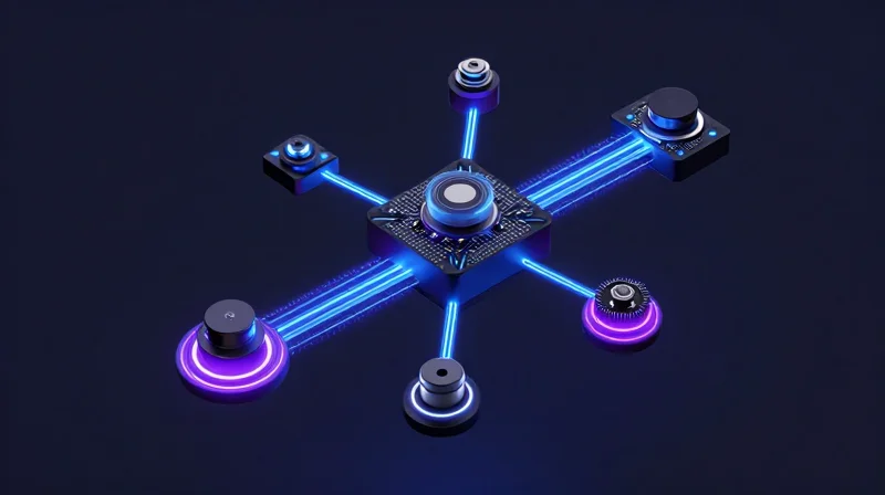
Achieving seamless sensor fusion requires more than high-speed processors; it demands a robust physical layer capable of minimizing latency between image capture and decision-making logic. As miniaturized cameras shift from traditional rigid PCBs to integrated flexible or stacked interconnects, the primary challenge becomes maintaining signal integrity across multi-gigabit interfaces like MIPI CSI-2.
Modern PCB layouts now incorporate high-density interconnects (HDI) that place compute engines closer to the imaging sensors. By reducing the physical distance and utilizing advanced substrate materials, engineers can suppress electromagnetic interference (EMI) that often plagues high-bandwidth automotive data paths, ensuring that raw frame data remains synchronized across environmental shifts.
Comparative Analysis: Traditional vs. Miniaturized Data Paths
| Feature | Traditional Rigid PCB | Next-Gen Miniaturized Architecture |
|---|---|---|
| Data Latency | Moderate to High | Ultra-low (Near-sensor processing) |
| Signal Integrity | Prone to EMI at length | Shielded high-speed differential pairs |
| Component Density | Low | Extreme (SoC integration) |
| Thermal Distribution | Uniform/Bulk | Targeted (Heat-spreading substrates) |
Critical Considerations for Fusion Integration
- How does PCB layout impact fusion reliability?
A well-optimized layout reduces signal reflections and cross-talk, which are the primary causes of data packet loss in high-resolution multi-camera systems. - Why is thermal management vital for fusion?
Thermal throttling on a camera module induces frame drops or jitter, creating a 'temporal drift' that ruins the timing accuracy required for object tracking in autonomous algorithms. - What is the role of advanced substrates?
Materials like liquid crystal polymer (LCP) or specialized ceramics provide low dielectric constants, allowing for thinner, faster trace designs that facilitate higher data throughput in confined spaces.
Overcoming Thermal and Reliability Challenges
Mitigating Thermal Stress in Compact Architectures
As automotive cameras shrink, the power density within the sensor-ISP assembly rises, creating significant thermal management hurdles. Traditional PCB architectures often rely on bulky heat sinks, but next-gen miniaturized solutions utilize advanced thermal interface materials (TIMs) and integrated metal-core PCBs (MCPCBs) to dissipate heat efficiently across smaller surface areas. By leveraging high-thermal-conductivity substrates and thermal vias that connect directly to the vehicle chassis, engineers can maintain sensor performance stability even during intense continuous operation.
Reliability Metrics: Traditional vs. Miniaturized
| Parameter | Traditional PCB | Miniaturized Next-Gen |
|---|---|---|
| Thermal Path | External Heat Sink | Integrated Substrate/Chassis |
| Vibration Fatigue | Lower susceptibility | High resilience via flex-rigid structures |
| Thermal Expansion | CTE Mismatch issues | Matched CTE material stacks |
Frequently Asked Questions
- How does miniaturization affect the AEC-Q100 reliability qualification?
Miniaturization requires more rigorous validation of solder joint integrity and inter-layer adhesion, often necessitating the use of underfill materials to prevent stress-induced fractures under extreme thermal cycling. - Can flexible circuit boards meet automotive vibration standards?
Yes, when correctly implemented with stress-relief loops and reinforced anchor points, flex circuits offer superior mechanical resilience compared to rigid boards, as they absorb rather than transmit vibrational forces. - What is the role of CTE matching in these new designs?
Coefficient of Thermal Expansion (CTE) matching is critical in compact camera modules to ensure that the PCB, sensor, and housing expand and contract at the same rate, preventing misalignment or detachment during temperature fluctuations.
Future-Proofing Vehicle Design with Compact Architectures
The Evolution of Spatial Efficiency in Camera Packaging
As Advanced Driver Assistance Systems (ADAS) demand a higher density of sensors, the traditional bulky PCB approach is becoming an obstacle to vehicle ergonomics and aerodynamic profiling. By adopting System-in-Package (SiP) technology and modular camera architectures, manufacturers can significantly reduce the footprint of imaging modules. This transition enables designers to integrate high-resolution sensors into tighter, more discreet locations without compromising performance, thereby facilitating the 'seamless' design trend that modern consumers expect.
Strategic Impact: Traditional vs. Miniaturized Architectures
| Feature | Traditional PCB Architecture | Miniaturized Camera Solution |
|---|---|---|
| Form Factor | Large, rigid boards | Compact, integrated modules |
| Integration | High cabling complexity | Streamlined interconnects |
| Manufacturing Cost | Lower per-unit, high labor | Higher R&D, lower assembly cost |
| Thermal Management | Surface dissipation | Integrated heat dissipation |
Manufacturing and Compliance Considerations
The pivot toward miniaturized imaging is not merely a hardware change but a shift in the entire vehicle manufacturing philosophy. Automated assembly processes are increasingly favored as these micro-architectures allow for standardized pick-and-place manufacturing cycles. From a safety compliance perspective, these units are being engineered to support ISO 26262 functional safety requirements more natively, as shorter signal paths and shielded micro-components reduce electromagnetic interference risks and communication latency.
Strategic Outlook and FAQ
- How does miniaturization impact vehicle weight reduction targets?
Miniaturization significantly reduces the weight of cable harnesses and housing materials, contributing to improved vehicle energy efficiency and extended range for electric vehicle architectures. - Can these new architectures meet the 15-year automotive durability standard?
Yes; utilizing ceramic substrates and advanced encapsulation techniques ensures that miniaturized modules can withstand harsh vibration, thermal cycling, and moisture exposure equal to or better than traditional PCBs. - Will this transition make sensor replacement more difficult for repairs?
While component-level repair is restricted, the shift toward modular, plug-and-play designs simplifies the replaceability of the entire imaging unit during field maintenance.
Strategic Considerations for Automotive OEMs
Strategic Hardware Roadmapping
For automotive OEMs, the transition to miniaturized camera architectures represents more than a design choice—it is a strategic pivot that dictates future vehicle platform capabilities. Balancing the reliability of established PCB designs against the high-density requirements of next-gen systems requires a phased integration approach that prioritizes thermal management and supply chain resilience.
| Strategic Metric | Traditional PCB Approach | Miniaturized Camera Systems |
|---|---|---|
| Integration Complexity | Low (Standardized) | High (Advanced Packaging) |
| Thermal Dissipation | Passive/Conduction | Active/Micro-fluidic or Novel Heat-sink |
| Design Flexibility | Rigid (Limited) | Modular (High) |
Key Strategic Decision Factors
- How does miniaturization impact manufacturing throughput?
While miniaturization requires more precision in assembly, the reduction in component count and physical footprint allows for automated, high-speed pick-and-place processes that can lower total cost of ownership over time. - What is the primary risk regarding automotive-grade certification?
Adopting newer, miniaturized components can complicate AEC-Q100/102 qualification timelines. OEMs must ensure that vendors provide comprehensive reliability data that accounts for accelerated aging in smaller form factors. - How can OEMs avoid platform lock-in?
Focusing on modular camera interfaces (e.g., standardizing on specific high-speed serialization protocols) allows OEMs to upgrade sensor heads without re-engineering the entire central imaging control unit.
Future-Proofing Recommendations
To remain competitive, OEMs should adopt a 'Design for Change' philosophy. This involves building out PCB architectures that support hardware-in-the-loop (HiL) testing for heterogeneous sensors, enabling the vehicle to adapt as imaging standards evolve. Furthermore, investing in partnerships with Tier 1 suppliers that specialize in both optics and high-density PCB design will be critical to bridging the performance gap between traditional designs and future autonomous requirements.
The shift toward miniaturized, advanced PCB architectures is not merely an incremental upgrade—it is a fundamental requirement for the future of safe autonomous transportation. As vision systems become the eyes of the vehicle, choosing the right technological foundation is paramount. Contact our engineering team today to learn how our advanced sensor solutions can elevate your automotive design projects.
