
As ADAS systems move toward higher resolution and increased range, the reliability of radar sensors depends entirely on the high-frequency circuit materials at their core. In this guide, we break down the technical parameters that define the next generation of safe, reliable automotive radar performance.
The Critical Role of PCB Materials in Radar Performance
Substrate Selection as a System Component
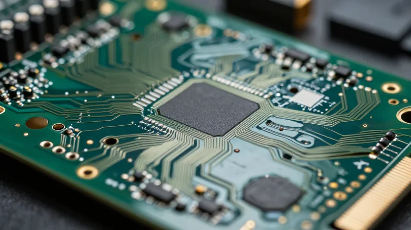
In automotive ADAS radar systems, the PCB material is not merely a structural carrier; it functions as an active component of the high-frequency circuit. Because these systems operate at 77 GHz to 79 GHz, the substrate's dielectric properties directly influence signal propagation speed, attenuation, and phase stability. A marginal error in material selection can lead to significant signal loss, compromising the radar's ability to discern obstacles at long range.
Key Performance Metrics
| Parameter | Impact on Radar Performance | Critical Threshold |
|---|---|---|
| Dk (Dielectric Constant) | Determines signal impedance and phase velocity. | Low and stable (TCDk < 50 ppm/C) |
| Df (Dissipation Factor) | Controls insertion loss and heat generation. | Ultra-low (< 0.002 at 77 GHz) |
| Surface Roughness | Affects conduction loss at high frequencies. | Minimize (Low profile copper) |
Thermal Stability and Reliability
Automotive environments demand extreme thermal robustness. Radar modules mounted behind bumpers are subjected to intense ambient fluctuations. Materials with high Coefficient of Thermal Expansion (CTE) can induce mechanical stress, causing micro-cracking in vias and inconsistent signal paths. Ensuring a low Dk/Df temperature coefficient is essential to prevent 'thermal drift' in detection range as the sensor heats up during operation.
Frequently Asked Questions
- Why is standard FR-4 unsuitable for ADAS radar?
FR-4 suffers from high dielectric loss and inconsistent Dk values at 77 GHz, leading to severe signal attenuation and erratic radar behavior. - How does surface roughness impact signal loss?
At millimeter-wave frequencies, the skin effect concentrates current at the copper surface; high roughness increases the effective path length, significantly increasing conductor loss. - What is the primary risk of inconsistent Dk?
Variation in Dk across the board leads to impedance mismatches and phase errors, causing ghost targets or reduced resolution in the radar imaging.
Dielectric Constant (Dk) Stability Across Temperature
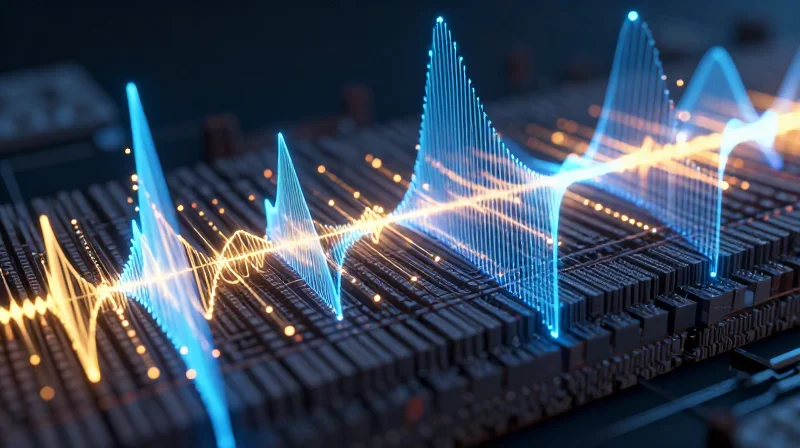
In automotive radar systems, the dielectric constant (Dk) of the PCB substrate is the primary determinant of electromagnetic wave propagation velocity. Because radar sensors are mounted in environments subject to extreme temperature swings—ranging from -40°C in winter to over 125°C under the hood—the material's thermal stability is paramount. A substrate whose Dk shifts significantly with temperature will cause phase variations in the radar signal, leading to ghosting, range errors, and degraded spatial resolution in ADAS perception systems.
Understanding Thermal Dk Coefficient
The Thermal Coefficient of Dielectric Constant (TCDk) measures the rate of change in a material's Dk relative to temperature. For precision radar applications (e.g., 77GHz systems), engineers must target materials with a TCDk approaching zero. High TCDk values cause the electrical length of transmission lines to drift, which directly compromises the phase-locked loops (PLL) and timing accuracy required for Frequency Modulated Continuous Wave (FMCW) radar.
| Material Class | Typical TCDk (ppm/°C) | Suitability for 77GHz Radar |
|---|---|---|
| Standard FR-4 | 500 to 1000 | Unsuitable |
| Filled PTFE/Ceramic | 10 to 50 | High Performance |
| Thermoset Hydrocarbon | 40 to 80 | Good Performance |
Common Challenges and Solutions
- How does Dk shift affect signal processing?
A fluctuating Dk changes the signal propagation velocity, leading to phase errors that the signal processor may interpret as false targets or distance measurement offsets. - Why is ceramic-filled material preferred?
Ceramic-filled composites offer superior structural rigidity and lower coefficients of thermal expansion, which helps pin the dielectric properties in place across the automotive temperature range. - Can software compensate for Dk drift?
While some digital compensation exists, it adds computational latency and complexity; hardware-level Dk stability is always preferred to ensure a high signal-to-noise ratio at the source.
When selecting materials, prioritize substrates with low-loss profiles and flat TCDk responses. Designing for robustness requires a transition away from standard glass-reinforced epoxies toward advanced fluoropolymer or ceramic-filled hydrocarbon matrices, ensuring the radar system remains calibrated and reliable regardless of environmental stress.
Minimizing Signal Loss: The Importance of Dissipation Factor
In the context of automotive ADAS radar—typically operating in the 77 GHz to 79 GHz bands—the dissipation factor (Df), also known as the loss tangent, is the primary driver of signal attenuation. As electromagnetic waves propagate through a PCB substrate, a portion of the signal energy is converted into heat due to molecular friction within the dielectric material. For high-frequency radar modules, where every decibel of return loss is critical to detect distant objects, selecting a substrate with an ultra-low Df is non-negotiable to maintain a robust signal-to-noise ratio.
Energy Budget and Signal Integrity
High-frequency signals encounter significant insertion loss as they traverse PCB traces, particularly over longer path lengths common in complex sensor arrays. A material with a high Df effectively narrows the radar's 'vision,' limiting the detection range because the return echoes are attenuated below the system's noise floor before they can be processed. By utilizing low-loss PTFE-based or advanced hydrocarbon laminates, engineers can reclaim critical signal power, allowing the radar front-end to distinguish smaller cross-section targets at greater distances.
| Material Type | Typical Df (at 77GHz) | Impact on Radar Performance |
|---|---|---|
| Standard FR-4 | 0.020+ | Extreme attenuation; unusable for 77GHz radar. |
| High-Frequency Laminate (Mid-range) | 0.003 - 0.005 | Acceptable for short-range; signal loss limits long-range. |
| Ultra-Low Loss PTFE Composite | < 0.0015 | Optimal; maximizes link budget and detection sensitivity. |
Frequently Asked Questions Regarding Dissipation Factor
- How does Df correlate to thermal management?
Materials with a high Df absorb more RF energy, which translates to internal heating. In high-power radar transmitters, this heat can shift the Dk and degrade the material over time, creating a destructive feedback loop. - Is Dk more important than Df?
While Dk stability is vital for phase accuracy and beam steering, Df is critical for raw signal strength. They are equal partners; Dk maintains the 'where,' while Df ensures the signal arrives with enough intensity to be processed. - Does frequency impact the Df value?
Yes, Df is frequency-dependent. It is essential to review the manufacturer's data sheets specifically for the 77-81 GHz range, as Df values often increase as operating frequencies rise.
Thermal Management and Coefficient of Thermal Expansion (CTE)
The Challenge of Thermal Expansion in Radar PCBs
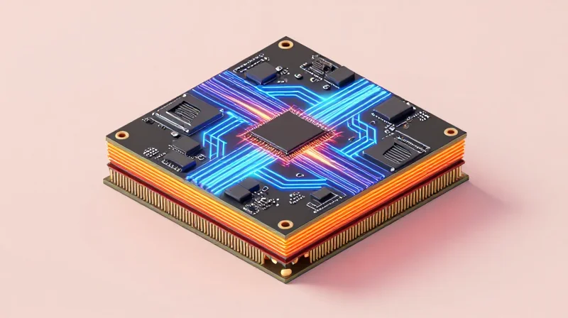
Automotive radar sensors operate in harsh environments where ambient temperatures can fluctuate from -40°C to +125°C. When a PCB substrate has a Coefficient of Thermal Expansion (CTE) that deviates significantly from the copper cladding or the metallic housing, thermal cycling causes mechanical stress. This expansion and contraction can lead to micro-cracking in plated-through holes (PTHs), trace lifting, or delamination, all of which catastrophically degrade the signal integrity of high-frequency radar modules.
Material CTE Comparison
| Material Type | Typical CTE (ppm/°C) | Thermal Reliability Impact |
|---|---|---|
| Standard FR-4 | 14-17 (in X/Y) | High risk of PTH failure in radar apps |
| Ceramic-filled PTFE | 8-12 | Excellent stability, matches copper |
| Hydrocarbon Ceramic | 10-15 | Very good, balances cost and stress |
Designing for Thermal Robustness
To mitigate thermal-induced failure, engineers must prioritize materials with a low Z-axis CTE to protect the vertical interconnects. Furthermore, the glass transition temperature (Tg) must be significantly higher than the peak operating temperature of the radar module to ensure the substrate remains in its glassy, stable state rather than transitioning to a softer, rubbery state that induces parasitic signal shifts.
- Why is Z-axis CTE more critical than X/Y in radar systems?
The Z-axis CTE determines the stress placed on the barrel of through-hole vias. High Z-axis expansion causes the via barrel to stretch and eventually crack, leading to open circuits. - How does thermal management influence radar accuracy?
In addition to mechanical failure, thermal stress alters the physical dimensions of the antenna array. Even microscopic changes in geometry can lead to beam steering errors and decreased sensor range. - Is a high Tg always necessary?
Yes. A high Tg ensures the material does not soften or significantly increase its expansion rate at high operational temperatures, maintaining physical stability for fine-pitch radar traces.
Surface Roughness and its Impact on Insertion Loss
Surface Roughness and its Impact on Insertion Loss
At 77GHz frequencies, the skin effect confines current flow to a very thin layer of the copper conductor, meaning the physical profile of the copper foil significantly influences signal attenuation. Higher surface roughness increases the effective path length of the current, leading to higher conductor loss. Therefore, minimizing copper profile roughness is a critical requirement for maintaining the performance of long-range ADAS radar modules.
Copper Profile Types and Performance
| Foil Type | Roughness (Rz) | Suitability for 77GHz |
|---|---|---|
| Standard ED | High (> 3.0 µm) | Poor |
| Low Profile (LP) | Medium (1.5 - 2.5 µm) | Moderate |
| Very Low Profile (VLP) | Low (0.5 - 1.0 µm) | Good |
| Hyper-smooth / Rolled | Very Low (< 0.5 µm) | Excellent |
Frequently Asked Questions
- Why does copper roughness matter at 77GHz?
As frequency increases, the skin depth decreases. When the skin depth approaches the dimension of the surface roughness, the electrons encounter the jagged topography, causing resistive losses and impacting signal phase consistency. - Is there a trade-off when using smoother copper?
Yes. While smoother copper significantly reduces insertion loss, it often provides lower peel strength for adhesion to the dielectric substrate, which can complicate PCB fabrication and long-term reliability under thermal cycling. - What should design engineers prioritize?
Engineers must strike a balance between RF performance and mechanical robustness by selecting HVLP (Hyper Very Low Profile) or similar specialized copper foils that offer optimal signal integrity without compromising the structural integrity of the radar board.
Compliance with Automotive Standards: IATF 16949 and AEC-Q100
Navigating Automotive Compliance Requirements
For high-frequency PCB materials in ADAS radar applications, compliance is not merely about electrical performance; it is about guaranteeing long-term reliability under extreme environmental stressors. Suppliers must demonstrate adherence to IATF 16949 quality management systems and validate component robustness through AEC-Q series testing protocols.
Distinguishing Between Quality and Qualification
| Framework | Primary Focus | Role in Material Selection |
|---|---|---|
| IATF 16949 | Quality Management System | Ensures manufacturing consistency and defect prevention in the supply chain. |
| AEC-Q100/Q006 | Component Stress Testing | Validates that the physical and electrical integrity survives automotive lifetime stress. |
Critical Considerations for Radar PCB Materials
- Why is IATF 16949 critical for material selection?
It mandates a zero-defect mindset and rigorous traceability. When selecting a high-frequency laminate vendor, confirming their IATF 16949 certification ensures that every batch of material produced adheres to the tight tolerances required for 77GHz radar performance. - Does AEC-Q100 apply directly to raw PCB laminates?
AEC-Q100 is primarily for integrated circuits, but radar modules must pass environmental stress tests defined by AEC-Q100 (and associated IPC-6012 standards). Materials must be pre-qualified to survive the thermal cycling, humidity, and mechanical shock regimes outlined in these specifications. - What role does material datasheet validation play in compliance?
Compliance requires that the electrical performance (Df/Dk stability) remains consistent after accelerated aging tests. Engineers must verify that the material manufacturer has documented behavior changes under long-term thermal exposure as specified in industry standards.
Selecting materials without established automotive-grade track records introduces unacceptable risk to the ADAS radar system lifecycle. Ensure your high-frequency laminate supplier provides documented proof of compliance, including data on how their materials perform under the rigorous thermal and mechanical profiles demanded by Tier-1 automotive integrators.
Manufacturing Feasibility and PCB Fabrication Considerations
Optimizing Material Chemistry for Standard Fabrication
High-frequency PTFE-based materials often require specialized handling due to their low bond strength and coefficient of thermal expansion (CTE) mismatch compared to standard FR-4. Automotive radar manufacturers must prioritize materials that demonstrate compatibility with standard subtractive etching, multi-layer lamination, and drilling processes to minimize throughput costs while maintaining signal integrity at 77GHz.
Material Performance Comparison for Fabrication
| Material Class | Fabrication Complexity | Bonding Reliability | Best Application |
|---|---|---|---|
| Ceramic-filled PTFE | High | Moderate | Long-range Radar |
| Thermoset Hydrocarbon | Low | High | Mid-range ADAS |
| Modified Epoxy/PPE | Very Low | Very High | General ADAS |
Interconnect Reliability and Plating Considerations
Reliability in automotive radar hinges on the integrity of micro-via structures and plating adhesion. Plasma desmear processes are essential when using high-frequency laminates, as they ensure clean inter-layer connections without damaging the dielectric structure. Selecting materials that exhibit high peel strength ensures that surface-mount technology (SMT) components remain attached under severe vibrational and thermal fatigue scenarios.
Manufacturing FAQ
- Does PTFE require a unique drilling profile?
Yes, PTFE-based materials are soft and prone to smearing; high-speed drilling with optimized entry/exit materials and frequent tool changes are required to prevent hole-wall roughness. - Why is the moisture absorption rate critical?
Materials with high moisture absorption can undergo dielectric constant shifts during operation and risk delamination or explosive degassing during the lead-free reflow process. - How does surface finish affect radar reliability?
Electroless Nickel Immersion Gold (ENIG) is common, but Immersion Silver or specialized organic solderability preservatives (OSP) are often preferred for high-frequency performance to avoid the signal loss associated with ferromagnetic nickel.
Future-Proofing Your Design: Trends in Next-Gen Radar
The Evolution Toward 79GHz-81GHz and Beyond
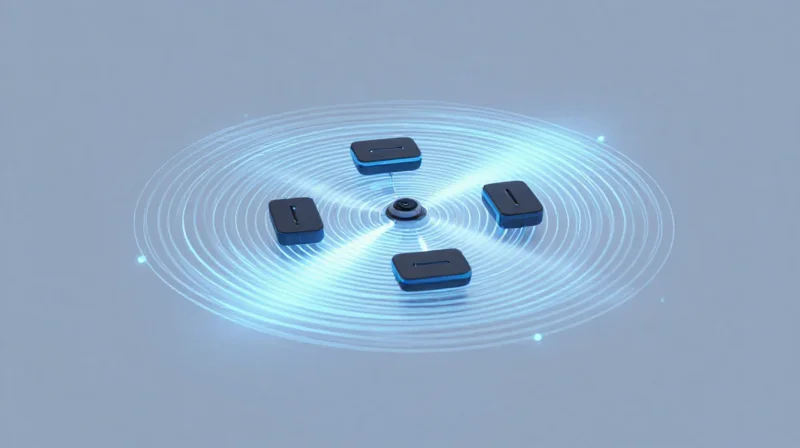
As automotive ADAS architectures move toward higher-resolution imaging radar, the industry is shifting from 76-77GHz to the 77-81GHz band. This increase in bandwidth requires PCB materials with ultra-stable dielectric constants (Dk) and ultra-low dissipation factors (Df) that remain consistent across wider temperature ranges and humidity levels. Designers must prioritize substrates that minimize dispersion, as signal integrity degradation becomes significantly more acute at these higher frequencies.
Material Performance Metrics for Next-Gen Requirements
| Requirement | Legacy ADAS (77GHz) | Next-Gen Radar (81GHz+) |
|---|---|---|
| Df (Dissipation Factor) | 0.0025 - 0.0030 | < 0.0020 |
| Dk Stability | Within +/- 0.05 | Within +/- 0.02 |
| Copper Profile | Low Profile | VLP / Hyper-Smooth |
| Interconnect Density | Standard HDI | Ultra-HDI / LDI |
Key Trends and Future Readiness FAQ
- How does sensor miniaturization affect material choice?
Smaller footprints require thinner laminates and higher-density interconnects, which often complicates thermal management. Materials must now balance high-frequency performance with improved thermal conductivity to dissipate heat generated by denser RF IC integration. - Is hybrid board construction becoming the standard?
Yes, cost-effective design often involves hybrid multi-layer stacks, combining high-performance PTFE or thermoset substrates for RF layers with standard FR-4 or high-Tg materials for logic layers, provided the CTE mismatch is strictly controlled. - Will digital modulation changes impact PCB material needs?
Increased use of complex digital modulation requires lower latency and better jitter performance, necessitating materials with superior surface smoothness to mitigate the skin effect, which becomes the dominant loss factor at higher GHz ranges.
Selecting the right PCB laminate is a balance of physics, thermal management, and strict regulatory compliance. By prioritizing stable dielectric properties and low loss, you ensure the safety and reliability of your ADAS radar systems. Contact our engineering team today to discuss your specific project requirements and optimize your design for the road ahead.
