
In the modern automotive landscape, keyless entry systems serve as the digital handshake between driver and vehicle. When these systems fail due to repeated mechanical stress or environmental thermal cycling, the result is more than a mere inconvenience—it is a brand reputation risk. Selecting the correct flexible PCB substrate is the fundamental engineering decision that determines whether your device will survive for a decade of daily use or fail prematurely in the field.
Understanding the Automotive Duty Cycle
Analyzing the Automotive Duty Cycle
The automotive duty cycle for smart keyless entry systems is uniquely punishing, characterized by a transition from extreme environmental exposure to high-frequency mechanical interaction. Unlike consumer electronics that reside in climate-controlled environments, key fobs are subjected to rapid thermal cycling, chemical exposure from automotive fluids, and the persistent mechanical fatigue of daily button actuation. Achieving long-term reliability requires flexible PCBs (FPCs) engineered to maintain electrical integrity through thousands of bending cycles and significant thermal shifts.
Environmental and Mechanical Stress Factors
| Factor | Source of Stress | Impact on FPC |
|---|---|---|
| Thermal Cycling | Cabin temp extremes (-40°C to +85°C) | Material delamination and solder joint cracking |
| Mechanical Fatigue | Repetitive button actuation | Conductive trace work-hardening and fracturing |
| Chemical Exposure | Oils, salts, and humidity | Substrate degradation and corrosion of exposed copper |
Frequently Asked Questions on Reliability
- Why is copper ductility critical for automotive FPCs?
Automotive environments often involve vibrations and frequent bending; high-ductility rolled-annealed (RA) copper provides the necessary elasticity to prevent trace fractures compared to standard electro-deposited copper. - How does moisture ingress affect flexible circuit lifespan?
Polyimide substrates, while generally robust, can absorb humidity, leading to dielectric breakdown. Properly sealed designs with appropriate coverlay materials are essential to prevent short circuits in humid environments. - What is the primary cause of solder joint failure in key fobs?
Coefficient of Thermal Expansion (CTE) mismatch between the flexible substrate and the rigid components creates mechanical stress during temperature swings, often leading to fatigue at the solder interface.
Evaluating Substrate Materials: Polyimide vs. Polyester
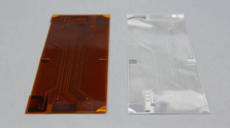
Material Performance: Polyimide vs. Polyester
For automotive keyless entry systems, the choice between polyimide (PI) and polyester (PET) substrates often dictates the lifecycle reliability of the flexible circuit. Polyimide stands as the industry gold standard for high-temperature applications due to its exceptional thermal stability and mechanical robustness. In contrast, polyester offers a cost-effective alternative for consumer-grade electronics but often lacks the heat resistance required for the rapid thermal cycling typical of automotive cabin environments.
| Property | Polyimide (PI) | Polyester (PET) |
|---|---|---|
| Glass Transition (Tg) | > 300°C | ~80-100°C |
| Thermal Resistance | Excellent (Solder reflow safe) | Low (Heat sensitive) |
| Dimensional Stability | High | Moderate |
| Automotive Suitability | High-Reliability | Consumer/Low-Cost |
Critical Considerations for Automotive Reliability
- Why is Polyimide preferred for soldering?
Polyimide possesses high heat resistance, allowing it to withstand standard surface mount technology (SMT) reflow soldering temperatures without delamination or degradation, whereas PET will deform or melt. - How does chemical compatibility impact material choice?
Automotive environments often expose key fobs to cleaning agents, fuel vapors, and lubricants. Polyimide offers superior chemical resistance, maintaining structural integrity under these conditions compared to PET, which can be susceptible to solvent swelling. - Does moisture absorption affect performance?
While both materials have some moisture absorption, polyimide is generally more stable in humid, fluctuating thermal conditions, preventing the 'popcorning' effect during rapid temperature spikes inside a parked vehicle.
For engineers designing high-reliability systems, polyimide is the required substrate. While PET may reduce material costs in high-volume, low-stress applications, the unpredictable thermal peaks within automotive interior environments make polyimide the only viable choice to ensure long-term functionality and prevent intermittent failures in smart keyless entry components.
The Criticality of Bend Radius and Flexibility
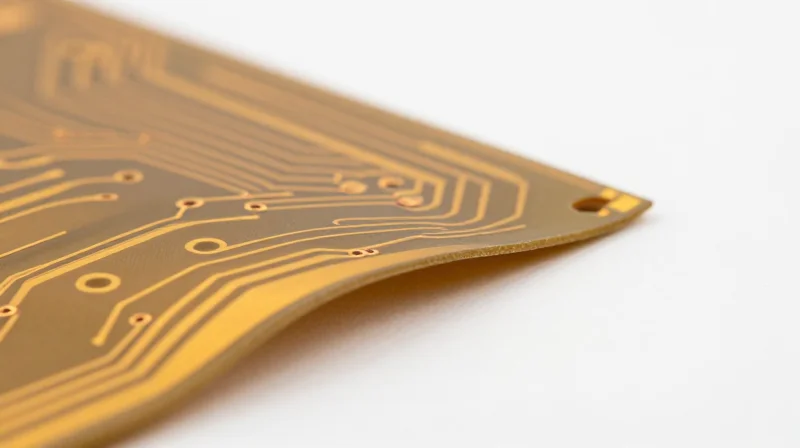
The Engineering Mechanics of Flex Fatigue
In dynamic automotive applications, the flex circuit is subjected to constant mechanical stress. The critical design parameter here is the minimum bend radius, defined as the smallest radius a flexible circuit can be bent without damaging the conductive traces or the dielectric base. When a PCB is bent beyond its designed limit, the copper traces experience extreme tensile or compressive stress, leading to microscopic work hardening, crack initiation, and eventual electrical open circuits.
Bend Radius Guidelines for High-Reliability
| Circuit Type | Bend Factor (Static) | Bend Factor (Dynamic) |
|---|---|---|
| Single-Sided | 6x-10x Thickness | 20x-30x Thickness |
| Double-Sided | 12x-15x Thickness | 40x-60x Thickness |
| Multilayer | 20x-25x Thickness | 80x-100x Thickness |
For automotive smart entry modules, engineers should prioritize 'neutral axis' design techniques. By placing conductive traces in the center of the total stack-up thickness, the copper experiences significantly less strain during bending cycles. Avoiding rigid-to-flex transitions near high-vibration points is also vital for longevity.
Frequently Asked Questions on Flexibility
- How does copper grain structure affect flexibility?
For high-reliability, always specify Rolled Annealed (RA) copper instead of Electro-Deposited (ED) copper. RA copper possesses a grain structure that is more elongated, offering superior resistance to cracking during repetitive bending. - Can I use surface finishes to improve flex reliability?
Certain rigid finishes like Electroless Nickel Immersion Gold (ENIG) can be brittle. In dynamic flex zones, consider using thinner plating or localized hardening to prevent the finish from cracking and inducing stress fractures in the underlying copper. - Does trace width influence bend performance?
Yes; narrower traces typically exhibit better flexibility than wider traces. Staggering traces in a multi-layer design prevents the build-up of mechanical stress concentrations across the cross-section.
Copper Weight and Signal Integrity Considerations
In automotive keyless entry systems, flexible PCBs must bridge the gap between high-current requirements for motor actuation and the high-frequency demands of RF communication. Selecting the correct copper weight is a multi-dimensional challenge: increasing copper thickness enhances current carrying capacity and thermal reliability but introduces parasitic capacitance and signal skew that can degrade RF performance.
Balancing Current Capacity and RF Stability
Engineers often face a trade-off where thicker copper (e.g., 1 oz or higher) is necessary to reduce IR drop and heat dissipation issues in power traces. However, thicker traces increase the cross-sectional area, which can lead to uncontrolled impedance in high-speed data lines. For reliable automotive performance, signal integrity (SI) simulation must be conducted to ensure that chosen copper weights do not cause reflections or excessive signal attenuation at RF operating frequencies.
| Copper Weight (oz) | Application Focus | SI Impact | Flexibility Trade-off |
|---|---|---|---|
| 0.5 oz | High-speed RF signals | Low parasitic capacitance; optimal | Highest flexibility; minimal stress |
| 1.0 oz | General power/logic | Moderate; manageable trace width | Standard; balanced fatigue life |
| 2.0+ oz | High-current actuators | High signal skew; skin effect risks | Increased stiffness; reduced reliability |
Critical Considerations for Automotive Reliability
- How does copper thickness affect impedance matching?
Thicker copper requires narrower traces to maintain a target impedance (usually 50 ohms), which increases manufacturing tolerance sensitivity and potential signal loss due to etching side-wall variations. - Why is the skin effect critical at RF frequencies?
As frequency increases, current travels primarily on the outer surface of the conductor. Using copper weights beyond necessity increases signal attenuation, which can impede the reliable range of keyless entry sensors. - What is the impact on mechanical durability?
Thicker copper layers significantly increase the neutral axis shift, leading to greater mechanical stress during bending and a higher probability of fatigue-induced fractures in high-vibration automotive environments.
For high-reliability automotive systems, we recommend using thinner copper for signal routing (0.5 oz) combined with heavy copper internal layers for power distribution only where necessary. Utilizing electro-deposited (ED) copper instead of rolled-annealed (RA) can sometimes improve signal transmission characteristics, but for flexible automotive applications, RA copper remains the gold standard for long-term crack resistance.
Managing Thermal Expansion and CTE Mismatch

Understanding the Impact of CTE Mismatch
In automotive smart keyless entry systems, flexible PCBs undergo extreme temperature fluctuations ranging from deep winter cold to intense heat generated by direct sun exposure. A significant CTE mismatch occurs when the substrate material expands at a different rate than the copper circuitry or the bonded components. Over time, this cyclical differential expansion induces shear stress on solder joints, leading to micro-cracking and eventual electrical failure of the connection.
CTE Comparison of Common FPCB Materials
| Material Layer | Typical CTE (ppm/°C) | Impact on Stability |
|---|---|---|
| Polyimide (PI) Substrate | 16 - 20 | Stable; closely matches copper. |
| Rolled Annealed Copper | 17 - 18 | Baseline for interconnects. |
| Acrylic Adhesive | 60 - 100 | High; requires thin bonding layers. |
| Coverlay Material | 20 - 30 | Moderate; ensures structural integrity. |
Design Strategies for Thermal Reliability
- Why is adhesive thickness critical?
Acrylic adhesives often have a much higher CTE than polyimide or copper. By minimizing the bond-ply thickness, engineers reduce the total volume of high-CTE material, thereby limiting the force exerted on the copper traces during thermal cycling. - How does grain structure influence CTE?
The use of Rolled Annealed (RA) copper is essential for high-reliability systems because its grain structure is more ductile and accommodates thermal expansion cycles better than Electro-Deposited (ED) copper, which is prone to stress-induced cracking. - Should I use adhesive-less laminates?
Yes. Adhesive-less copper-clad laminates eliminate the most significant source of thermal instability in the stack-up, as the copper is deposited directly onto the polyimide, resulting in a more uniform CTE profile across the thickness of the circuit.
To achieve long-term field success, design teams must prioritize a 'balanced' stack-up. By centering the neutral axis of the flex circuit and ensuring that CTE values are graduated rather than abrupt between layers, the system can distribute mechanical stress more effectively. For keyless entry fobs subjected to thousands of ignition cycles, selecting polyimide-based constructions with adhesive-less laminates remains the gold standard for preventing field returns due to thermal fatigue.
Adhesive Systems and Their Impact on Longevity
Adhesive-Based vs. Adhesive-Less Construction
In automotive applications, the interface between the copper foil and the polyimide dielectric is the most vulnerable point in a flexible circuit. Adhesive-based systems utilize acrylic or epoxy resin layers to bond the copper. While cost-effective and easier to manufacture, these adhesives possess higher Coefficients of Thermal Expansion (CTE) than the base films, potentially leading to delamination or barrel cracking under the extreme temperature fluctuations typical of automotive environments. Conversely, adhesive-less constructions utilize a direct copper deposition or laminating process, which creates a thinner, more thermally stable, and chemically resistant bond.
| Feature | Adhesive-Based | Adhesive-Less |
|---|---|---|
| Thermal Stability | Moderate (Adhesive CTE issues) | High |
| Total Thickness | Higher (Due to adhesive layers) | Thinner |
| Dimensional Stability | Lower | Superior |
| Cost | Lower | Higher |
| Reliability Expectation | Standard Automotive | Mission-Critical / High-Temp |
Impact on Automotive Longevity
For smart keyless entry systems, which are subjected to constant vibrations and varied thermal cycles, adhesive-less circuits are increasingly the industry standard. Their reduced thickness allows for a tighter bend radius, which minimizes internal mechanical stress on the copper traces. Furthermore, the absence of low-glass-transition-temperature adhesives prevents the 'z-axis' expansion that causes via cracking during high-current operations or exposure to intense cabin heat.
- Why is adhesive-less construction preferred for high-reliability modules?
It eliminates the CTE mismatch between the adhesive layer and the substrate, resulting in significantly higher fatigue resistance during thermal cycling. - Does adhesive type affect signal integrity in high-frequency automotive sensors?
Yes, adhesive-less constructions offer more consistent dielectric constants throughout the substrate stack, which minimizes signal impedance discontinuities. - Can adhesive-based systems be used in automotive interiors?
They remain suitable for static, low-heat applications, but engineers must account for the mechanical limitations and potential outgassing of the adhesives at elevated temperatures.
Ensuring Compliance with Automotive Reliability Standards

Adhering to IPC-6013 and Automotive Standards
For automotive applications, compliance with IPC-6013 Class 3 is non-negotiable, as it mandates the highest level of performance and reliability for mission-critical electronics. Beyond IPC standards, manufacturers must ensure their flexible PCBs satisfy AEC-Q100 and AEC-Q200 qualification requirements. These standards verify that components and boards can withstand extreme temperature fluctuations, high-humidity environments, and severe mechanical vibration profiles inherent in modern vehicle chassis and smart keyless entry systems.
Environmental Stress Testing Protocols
| Stress Test | Automotive Requirement | Failure Mechanism Addressed |
|---|---|---|
| Thermal Cycling | -40°C to +125°C | Interconnect cracking and delamination |
| Damp Heat | 85°C / 85% RH | Electrochemical migration and corrosion |
| Vibration | Random/Sine profile | Solder joint fatigue and trace fractures |
FAQ: Compliance and Reliability Validation
- Why is IPC-6013 Class 3 critical for keyless entry?
Class 3 requires stricter tolerances for conductor width and insulation spacing, which are essential for maintaining the integrity of low-power radio frequency signals in security-sensitive automotive systems. - How does AEC-Q200 impact PCB material selection?
AEC-Q200 ensures that passive components and substrates are tested for thermal shock and bond strength, preventing premature failure of mounted sensors inside key fobs or door handles. - What documentation should I request from my PCB supplier?
Always demand a Certificate of Conformance (CoC), detailed test reports for thermal cycling, and evidence of ionic contamination testing to ensure long-term chemical stability.
Design for Manufacturing (DFM) Best Practices
Design for Manufacturing (DFM) Best Practices
DFM in the context of high-reliability automotive flexible electronics requires a meticulous approach to geometry and material selection to mitigate mechanical fatigue and manufacturing defects. By optimizing trace routing, bend radii, and stack-up symmetry, engineers can significantly reduce the risk of delamination and copper fatigue common in dynamic keyless entry environments.
Key Design Strategies for Flex Reliability
- Optimizing Trace Routing
Route traces perpendicular to the bend direction to prevent stress concentrations; always use 'I-beam' or 'staggered' construction to maintain balance across the flex layers. - Strategic Bend Radii
Design with a bend radius at least 10 times the thickness of the flexible circuit to avoid conductor cracking during repetitive installation or operation. - Neutral Axis Management
Ensure the copper traces are positioned as close to the neutral axis of the bend as possible to minimize compression and tension stresses during dynamic movement.
Common Manufacturing Pitfalls and Solutions
| Design Pitfall | Reliability Impact | Corrective Action |
|---|---|---|
| Sharp Corner Traces | Stress Risers/Fracture | Use rounded pads and fillets |
| Layer Misalignment | Impedance Mismatch | Implement generous annular rings |
| Coverlay Delamination | Moisture Ingress | Use staggered transition zones |
FAQ: DFM Optimization
- How does layer stack-up affect yield?
Asymmetric stack-ups lead to bowing and twisting during thermal excursions; maintaining a symmetric construction is critical for dimensional stability. - Is rigid-flex preferred over pure flex?
For smart keyless systems, rigid-flex provides robust anchor points for components while maintaining the necessary flexibility for slim-profile automotive enclosures.
Selecting the right flexible PCB substrate is an investment in your product's longevity and your customers' trust. By focusing on thermal stability, bend resilience, and material compatibility, you can ensure your keyless entry hardware meets the rigorous demands of the automotive sector. Contact our engineering team today to discuss your next high-reliability project and ensure your design is built for the long haul.
