
In the high-stakes world of electronic security, the integrity of your hardware is the foundation of user trust. As keyless access systems evolve toward more compact and sophisticated designs, the traditional reliance on rigid-flex PCBs is increasingly becoming a bottleneck. Engineering teams are now discovering that a strategic pivot toward advanced flexible PCB solutions is not just an aesthetic upgrade, but a powerful lever for reducing mechanical assembly complexity and driving long-term ROI.
The Current Landscape: Rigid-Flex Limitations
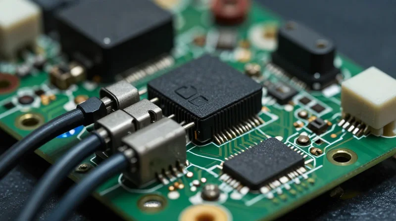
The Engineering Bottleneck in Conventional Rigid-Flex
Traditional rigid-flex printed circuit boards (PCBs) have long served as the standard for complex electronic packaging. However, in the high-stakes world of automotive and residential keyless entry, these legacy architectures often reach a breaking point. The reliance on bonded rigid-flex segments creates mechanical stress concentration points, leading to fatigue and failure in compact, high-vibration environments.
| Limitation | Impact on Keyless Entry | Assembly Consequence |
|---|---|---|
| Mechanical Stress | Interconnect failure due to repeated bending | Increased RMA and warranty costs |
| Z-Axis Thickness | Inability to meet ultra-thin housing profiles | Compromised aesthetic design |
| Manual Assembly | Higher labor costs for complex cabling | Increased potential for human error |
Addressing Common Misconceptions
- Why do rigid-flex boards lead to higher assembly costs?
The requirement for multiple interconnects, connectors, and bulky wiring harnesses adds significant labor time and material overhead that scales poorly in mass production. - Are current rigid-flex solutions reliable enough for harsh environments?
While durable, the transition zones between rigid and flex regions are frequent points of failure during thermal cycling, which is common in outdoor keyless entry hardware. - Does miniaturization suffer from rigid-flex architectures?
Yes. The required stiffeners and thick adhesive layers increase the volumetric footprint, preventing the sleek, ergonomic designs demanded by modern security hardware.
By shifting away from fragmented rigid-flex assemblies toward fully flexible or integrated circuit solutions, engineers can eliminate the redundant interfaces that drive up component counts and assembly complexity. This transition is not merely a design preference; it is a fundamental shift toward reducing total cost of ownership while enhancing long-term device reliability.
The Evolution to Advanced Flexible PCBs
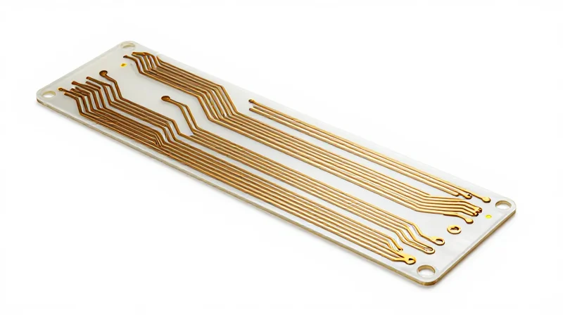
From Rigid-Flex to Full Flex Architecture
The evolution in keyless entry design is marked by a pivot from legacy rigid-flex assemblies to monolithic flexible PCB architectures. While rigid-flex was once the standard for overcoming space constraints, it introduced structural stress points at the interconnect interfaces. Modern fully flexible designs eliminate these mechanical failure points by integrating all logic, power, and connectivity onto a single, pliable substrate, significantly reducing the z-axis footprint and improving overall structural integrity.
Material Innovations Driving Adoption
Advanced flexible circuits now leverage high-performance polyimide films and thinner copper-clad laminates that accommodate tighter bend radii without compromising signal integrity. These material advancements allow engineers to fold the PCB into the complex internal geometries of door handles and proximity sensors, effectively turning the circuitry into a structural component of the device housing.
| Feature | Legacy Rigid-Flex | Advanced Flexible PCB |
|---|---|---|
| Mechanical Stress | High at transition zones | Uniformly distributed |
| Z-Axis Height | Variable/High | Minimal |
| Assembly Complexity | Multi-stage bonding | Single-stage integration |
| Reliability | Moderate | High |
Frequently Asked Questions
- How does full flexible integration reduce total assembly time?
By removing the need for auxiliary connectors, wire harnesses, and manual soldering of rigid-to-flex transitions, manufacturers can automate the final assembly process. - Are flexible PCBs durable enough for external automotive environments?
Yes, modern high-temperature polyimides provide excellent resistance to vibration, thermal cycling, and moisture ingress, exceeding the reliability requirements of automotive keyless entry systems.
Reducing Mechanical Assembly Time
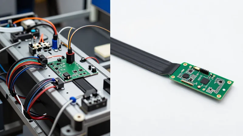
Eliminating Manual Interconnect Bottlenecks
The primary driver of assembly labor costs in legacy keyless entry designs is the reliance on manual cable harness installation. Rigid-flex or pure flexible PCB integration removes the need for physical cabling, connectors, and cable ties. By embedding the interconnect directly into the circuit design, manufacturers can execute a 'drop-in' assembly process, effectively moving from a multi-step manual wiring phase to a single automated positioning step.
Comparative Efficiency of Assembly Methods
| Assembly Metric | Legacy Rigid/Wiring | Flexible PCB Integrated |
|---|---|---|
| Component Count | High (Harnesses + Connectors) | Low (Integrated Circuit) |
| Assembly Time | 120-180 Seconds | 15-30 Seconds |
| Error Probability | High (Mis-wiring risk) | Near-Zero (Fixed routing) |
| Process Step | Manual Routing & Termination | Automated Placement |
Streamlining the Keyless Entry Production Line
Flexible PCBs facilitate higher throughput by enabling SMT (Surface Mount Technology) assembly lines to handle the entire interconnect structure. Since the flex circuit behaves as a standard component during the pick-and-place process, the manual labor requirement for connector mating is eradicated. This transition reduces human error associated with loose connections—a common failure point in automotive keyless entry systems—thereby reducing the costs associated with quality control and rework.
- How does flex integration reduce cycle time?
It eliminates the need for manual routing, crimping, and housing of cable harnesses, allowing the entire system to be mounted in one automated operation. - Does this approach impact long-term reliability?
Yes, by removing mechanical connectors, you eliminate contact oxidation and vibrational fatigue points, which are the primary drivers of field failures in keyless modules. - Can flexible PCBs fit into existing automated assembly lines?
Most flexible circuits are designed with rigid stiffeners in mounting areas, allowing them to be processed by standard pick-and-place machines without modifications to existing SMT infrastructure.
Optimizing Circuit Density for Compact Access Modules
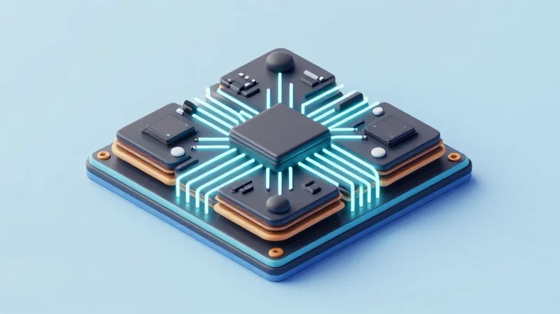
The Engineering Logic Behind High-Density Flexibility
Achieving compact form factors in keyless entry designs necessitates moving beyond traditional rigid circuit constraints. By utilizing Fine Line Technology (FLT) and Microvia structures within a flexible substrate, engineers can effectively double the routing density of standard boards. This optimization allows for a reduction in footprint without necessitating multi-layer rigid structures that add thickness, weight, and mechanical vulnerability to the final assembly.
| Feature | Rigid PCB Approach | High-Density Flex Approach |
|---|---|---|
| Routing Density | Standard (Baseline) | High (2x-3x increase) |
| Form Factor | Bulky/Fixed Geometry | Conforming/Ultra-thin |
| Signal Path | Connector-Dependent | Integrated Continuous Trace |
Optimizing Signal Integrity in Compact Environments
As circuits become more densely packed, the risk of signal crosstalk and impedance mismatch increases. To counteract this in compact keyless entry modules, we implement controlled impedance routing and differential pair shielding directly within the flexible layers. This integrated approach ensures that high-speed signals—essential for secure rolling-code transmission—remain robust even as the internal space within the key fob or access module is minimized.
Technical FAQ: Density and Integration
- How does density affect thermal management in small modules?
While density increases heat concentration, the thinner profile of flexible PCBs improves heat dissipation across the module surface compared to thick, insulating rigid FR-4 substrates. - Does high-density routing limit assembly flexibility?
On the contrary, high-density flexible circuits allow for 'origami' folding configurations, meaning the final geometry can be tailored to the specific enclosure volume without requiring extra wiring.
Case Study: Achieving Lower Total Cost of Ownership (TCO)
The Challenge: Assembly Inefficiency in Legacy Modules
A leading automotive electronics manufacturer faced mounting costs associated with the assembly of high-volume keyless entry fobs. The original design relied on rigid PCBs connected by bulky wire harnesses and manual soldering, leading to high failure rates during the automated assembly process and increased labor time during final integration.
Comparative Analysis: Rigid vs. Flexible Integration
| Metric | Legacy Rigid Assembly | Flexible PCB Integration | Impact |
|---|---|---|---|
| Assembly Steps | 14 steps | 6 steps | 57% Reduction |
| Manual Soldering | Required | None | Lower Labor Cost |
| Field Failure Rate | 1.8% | 0.3% | Improved Reliability |
Key Results and Financial Impact
By adopting a flexible PCB architecture, the manufacturer eliminated the need for fragile mechanical connectors and reduced the footprint of the internal circuitry by 35%. This integration facilitated an automated pick-and-place assembly flow, effectively removing the human error variable and significantly shortening cycle times.
Frequently Asked Questions
- How did flexible PCBs impact field maintenance?
By eliminating mechanical connectors, the number of potential failure points decreased, leading to a marked improvement in product longevity and a reduction in warranty claims. - Was the initial material cost of flexible PCBs higher?
Yes, the unit material cost for flexible substrates was roughly 12% higher, but this was rapidly offset by labor savings and the reduction of downstream manufacturing waste.
Enhancing Product Lifecycle and Reliability
Extending Operational Longevity in High-Traffic Environments
Keyless entry systems in commercial environments endure thousands of cycles, often exposed to vibrations from slamming doors and thermal expansion from fluctuating ambient temperatures. Rigid PCBs often face solder joint fatigue at connection points, leading to premature field failure. Flexible circuits (FPC) provide a resilient, dynamic interconnect solution that absorbs mechanical stress and vibration, effectively extending the MTBF (Mean Time Between Failure) of the device.
| Failure Driver | Rigid PCB Response | Flexible PCB Benefit |
|---|---|---|
| Mechanical Vibration | High risk of solder joint cracking | Excellent absorption and damping |
| Thermal Expansion | Rigid substrate stress-cracks | Elastic strain accommodation |
| Repetitive Cycling | Connector wear and fatigue | Seamless integration, no contact wear |
Maintenance and Reliability FAQ
- How do flexible PCBs reduce field maintenance costs?
By eliminating traditional board-to-board connectors—a primary point of failure—flexible PCBs remove oxidation risks and mechanical loosening, significantly reducing the frequency of on-site service calls. - Are flexible PCBs more resistant to environmental stressors?
Yes; their thin profile and lightweight composition minimize the impact of inertial forces and thermal expansion coefficients that would otherwise fatigue brittle components in rigid assembly environments. - Does switching to FPCs impact signal integrity over time?
In fact, FPCs maintain superior signal integrity by providing shorter, direct transmission paths that do not degrade through the mechanical loosening of interconnectors often found in legacy rigid-cable assemblies.
Investing in flexible electronics at the design stage shifts the ROI model from simple assembly cost-cutting to a long-term strategy of lifecycle optimization. The ability of FPCs to survive rigorous environmental conditions ensures that the keyless entry infrastructure remains operational years longer than traditional rigid alternatives.
Strategic Design Considerations for Engineers
Architectural Transition Strategies
Moving from rigid-only architectures to flex-integrated designs requires a paradigm shift in mechanical and electrical co-design. Engineers should focus on reducing connector counts and optimizing cable routing to capitalize on the inherent malleability of polyimide-based substrates.
| Feature | Rigid Architecture | Flex-Integrated Strategy |
|---|---|---|
| Assembly Effort | High (Manual wiring/harnessing) | Low (Automated ZIF/LIF insertion) |
| Interconnect Density | Limited by board space | High (Multi-plane routing) |
| Mechanical Stress | Localized solder joint risk | Distributed flex tolerance |
Key Engineering Considerations
- How does bend radius affect reliability?
Engineers must adhere to a strict minimum bend radius (typically 10x the circuit thickness) to prevent copper micro-cracking and trace fatigue during repetitive keyless entry actuation. - Why minimize connector interfaces?
Each mechanical connector is a potential point of failure; integrating components directly onto the flexible circuit eliminates these failure points, lowering assembly cost and improving signal integrity. - What is the role of stiffeners?
Strategically placing FR4 or polyimide stiffeners in areas requiring component mounting or connector mating provides the necessary rigidity for solder joints without compromising the flexibility of the interconnecting segments.
Workflow Best Practices
To maximize ROI, implement concurrent engineering workflows where mechanical enclosures are designed alongside the circuit layout. Utilizing 3D-modeling software to simulate the 'folded' state of the PCB in the early design phase is crucial to avoiding interference and ensuring the board fits precisely within compact keyless entry housing.
Future-Proofing Your Access Control Infrastructure
Adaptability in Rapidly Evolving Smart Security
The transition to flexible PCB architectures is not merely a cost-saving measure; it is a vital strategy for long-term scalability. By moving away from rigid, space-constrained designs, engineers can implement 'design-for-update' philosophies that allow for hardware revisions without total chassis redesigns.
| Feature | Rigid PCB Infrastructure | Flexible PCB Infrastructure |
|---|---|---|
| Form Factor Versatility | Fixed; requires specific housing | Adaptive; molds to geometry |
| Future Sensor Integration | Major board redesign required | Plug-and-play flexible extensions |
| Lifecycle Scalability | Low; prone to obsolescence | High; supports modular upgrades |
Anticipating Next-Generation Connectivity
Access control hardware is increasingly reliant on complex antenna arrays, UWB (Ultra-Wideband) chips, and advanced biometric modules. Flexible PCBs offer superior signal integrity for these high-frequency components by minimizing parasitic capacitance and allowing for optimal antenna placement that rigid boards cannot achieve due to physical footprint limitations.
Strategic Implementation FAQ
- How do flex PCBs prevent technological obsolescence?
They allow for smaller component density, leaving room for future sensor or communication module additions without changing the outer device dimensions. - Does switching to flex increase early-stage design time?
While initial layout requires specialized routing, the long-term gains in modularity and reduced assembly complexity far outweigh the marginal increase in front-end engineering hours. - Can flexible PCBs support high-power security features?
Yes, through the use of reinforced flexible laminates and strategic thermal management, flex PCBs can handle the power demands of modern biometric locks.
Transitioning to advanced flexible PCB solutions is a decisive step toward leaner manufacturing and more reliable field performance. By minimizing mechanical touchpoints and optimizing circuit density, you can significantly enhance your product's lifecycle while lowering operational expenses. Ready to optimize your keyless entry designs? Contact our engineering team today for a comprehensive design audit and start maximizing your ROI.
