
In modern vehicles, Electronic Power Steering (EPS) serves as a critical safety component. As steering systems move toward steer-by-wire and autonomous control, the underlying PCB technology must withstand extreme mechanical vibration, thermal cycling, and electrical noise. This guide provides an engineering roadmap for selecting substrates and assembly protocols that guarantee mission-critical reliability.
Understanding the Demands of EPS Applications
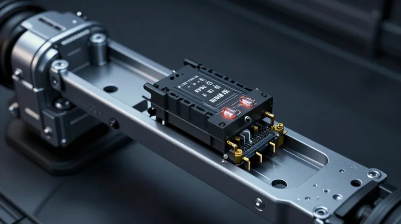
The Challenging EPS Operational Environment
Electronic Power Steering (EPS) systems are categorized as mission-critical automotive infrastructure. Unlike standard consumer electronics, EPS control units are mounted directly on or near the steering gear assembly, exposing them to a brutal combination of high-intensity electrical loads, significant mechanical vibrations, and cyclic thermal shock. A PCB failure in this context effectively leads to a complete loss of power assist, necessitating fail-safe architectural considerations during the material selection phase.
Key Environmental Stress Factors
| Stress Factor | Impact on PCB Integrity | Critical Requirement |
|---|---|---|
| Thermal Cycling | CTE mismatch causing solder joint cracks | High Tg (>170°C) laminates |
| High Current Density | Joule heating and trace delamination | Increased copper weight (2oz+) |
| Mechanical Vibration | Interconnect fatigue and micro-cracking | Advanced substrate bonding agents |
Engineering for Reliability: Common Questions
- Why is Coefficient of Thermal Expansion (CTE) critical for EPS?
As steering units heat up and cool down, different materials expand at different rates. If the PCB substrate's CTE is poorly matched to the copper traces, the internal stress will lead to barrel cracking in vias or pad lifting. - What role does high current density play in material selection?
EPS motors draw substantial transient currents. Boards must utilize thicker copper foils and high-performance pre-pregs to ensure thermal conductivity and prevent localized melting or insulation degradation. - How do we mitigate vibration-induced failures?
Beyond mechanical mounting, reliability is achieved through optimized stack-up symmetry and the use of flexible or high-ductility copper foils to withstand the constant mechanical resonance of the steering column.
Selecting the Right Substrate Material
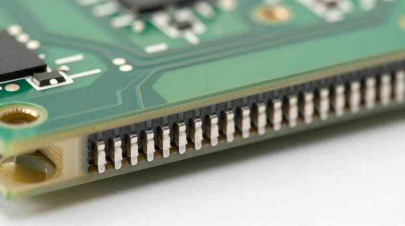
In the context of Electronic Power Steering (EPS), the PCB serves as the structural foundation for high-current power electronics. Because EPS units are often mounted directly on the steering rack, they are exposed to engine heat, vibration, and significant thermal cycling. Choosing the wrong substrate material leads to coefficient of thermal expansion (CTE) mismatches, resulting in PCB delamination, pad cratering, and solder joint fatigue.
High-Tg Laminates: The Foundation of Thermal Stability
High Glass Transition Temperature (Tg) laminates are mandatory for EPS applications. A standard FR-4 material, which typically transitions to a rubbery state around 130°C, is insufficient for the thermal peaks experienced during peak steering maneuvers. High-Tg materials, generally defined by a Tg above 170°C, offer superior dimensional stability and structural integrity, preventing the resin from softening when subjected to repeated heat cycles.
Ceramic-Filled Substrates and CTE Management
To further enhance reliability, engineers are increasingly turning to ceramic-filled laminates. These materials lower the Z-axis CTE, aligning it more closely with copper traces and surface-mount components. This alignment drastically reduces the mechanical stress placed on via barrels and solder interconnects during temperature fluctuations, effectively eliminating common failure modes found in standard polymer-only boards.
| Material Property | Standard FR-4 | High-Tg Laminate | Ceramic-Filled Laminate |
|---|---|---|---|
| Glass Transition (Tg) | 130-140°C | 170-180°C | 180°C+ |
| Z-Axis CTE | High | Moderate | Low |
| Thermal Conductivity | Low | Moderate | High |
| EPS Suitability | Unsuitable | Acceptable | Recommended |
Material Selection FAQ
- Why is Z-axis CTE mismatch a primary concern for EPS?
As the PCB expands and contracts due to power cycling, a high Z-axis CTE pulls at the copper interconnects in plated through-holes, eventually causing cracks that lead to open circuits. - Do ceramic-filled laminates impact the manufacturing process?
Yes, they require specialized drilling protocols due to their increased hardness, which can accelerate drill bit wear if the fabrication shop is not prepared for the abrasive filler material. - Should I choose copper-clad Invar or ceramic-filled laminates?
While Invar provides excellent physical constraint, ceramic-filled laminates are usually preferred for EPS due to their superior thermal conductivity, which helps dissipate heat from high-current power stages.
Copper Weight and Power Delivery Optimization
Managing High-Current Pulses with Heavy Copper
In Electronic Power Steering (EPS) systems, the motor control unit must manage significant current spikes, often exceeding 100A during rapid steering maneuvers. To maintain signal integrity and prevent localized overheating, designers must leverage heavy copper PCB technology. Implementing 2oz to 4oz copper weights is essential for minimizing I2R losses and reducing the heat dissipation burden on the thermal management system.
| Copper Weight (oz) | Current Capacity (Amp) | Thermal Benefit | Fabrication Difficulty |
|---|---|---|---|
| 1.0 | Low | Standard | Low |
| 2.0 | Medium | Good | Moderate |
| 4.0+ | High | Excellent | High |
Optimization Strategies for Trace Integrity
Beyond selecting the appropriate copper weight, trace geometry optimization is critical. Narrow traces under high current density lead to severe electromigration risks. We recommend utilizing wider conductive paths and ensuring consistent spacing to prevent arcing under the humid, vibration-heavy environments typical of automotive chassis mounting.
Design FAQ for Power Delivery
- How does heavy copper affect PCB etch factors?
Increased thickness requires wider spacing to account for greater etch undercut, which must be factored into the initial design layout to avoid short circuits. - What is the role of thermal vias in EPS designs?
Thermal vias should be filled and capped to provide a low-resistance path for heat to migrate from high-current components to the bottom layer or metal-core heat sinks. - Why is copper balancing necessary?
Uneven copper distribution on opposing sides of a PCB layer will cause the board to warp during reflow, leading to solder joint failure in the steering module.
Thermal Management and Heat Dissipation Techniques
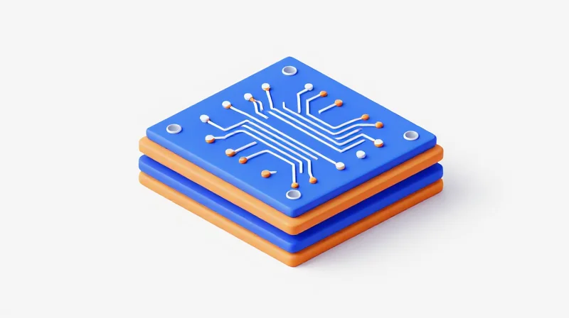
Advanced Thermal Dissipation Strategies for EPS
Electronic Power Steering systems generate significant localized heat due to high-current motor control and power conversion. To maintain junction temperatures within safe operating limits, engineers must employ integrated cooling techniques that leverage both the PCB substrate and the structural design of the board.
| Technique | Primary Application | Thermal Advantage |
|---|---|---|
| Metal Core PCBs (MCPCB) | Power Stages/MOSFETs | High thermal conductivity; direct heat sinking |
| Thermal Vias | Component Mounting Areas | Vertical heat transport to inner planes |
| Thick Copper Inlays | High Current Paths | Low resistance and rapid heat dissipation |
Implementing Thermal Vias and Metal Core Solutions
Thermal vias should be arranged in arrays directly beneath high-dissipation components to provide a low-thermal-resistance path to the internal ground or power planes. When using Metal Core PCBs (MCPCB), the dielectric layer thickness must be precisely controlled to balance electrical isolation requirements with thermal efficiency. In extreme power density scenarios, embedding a solid copper coin into the PCB provides a direct, low-thermal-resistance path to the vehicle chassis, effectively acting as an extension of the heat sink.
Frequently Asked Questions
- When should an MCPCB be preferred over standard FR-4?
MCPCBs are recommended for high-power EPS modules where standard board materials cannot sufficiently dissipate heat, typically when MOSFETs exceed 50-100W of localized dissipation. - How does via plating thickness affect thermal performance?
Increasing the copper plating thickness within thermal vias significantly improves the thermal conductivity and mechanical robustness of the board under the thermal cycling conditions inherent in automotive environments. - What is the critical consideration for thermal via array placement?
Vias should be placed as close as possible to the heat source and linked to large copper planes that can act as radiators; improper thermal isolation can lead to PCB warping or delamination.
Surface Finish Reliability for Automotive Longevity
Surface Finish Reliability for Automotive Longevity
In EPS applications, where safety-critical performance is non-negotiable, the surface finish acts as the primary defense against oxidation and intermetallic compound (IMC) brittleness. Automotive-grade PCBs require finishes that offer high solderability over extended lifespans while resisting the aggressive vibration profiles and wide temperature swings typical of steering assembly environments.
| Finish Type | Reliability Profile | Automotive Suitability |
|---|---|---|
| ENIG | Excellent shelf life, risk of black pad | Standard for low-power control |
| ENEPIG | Superior corrosion resistance, no black pad | High-reliability/Power-dense |
| Immersion Silver | Cost-effective, prone to creep corrosion | Restricted to sealed, inert zones |
Evaluating Finish Performance
- Why is ENEPIG preferred over ENIG for EPS modules?
ENEPIG (Electroless Nickel Electroless Palladium Immersion Gold) introduces a palladium layer that protects the nickel surface, significantly reducing the occurrence of 'black pad' failures and providing a more robust interface for high-stress solder joints. - Is Immersion Silver viable for automotive steering systems?
While cost-effective, Immersion Silver is susceptible to sulfur-induced creep corrosion. It should generally be avoided for EPS systems unless the final enclosure is hermetically sealed to prevent environmental contaminants from reaching the PCB. - How does surface finish affect long-term solder fatigue?
A high-quality surface finish ensures a uniform IMC layer. If the finish degrades due to improper thickness or chemistry, the resulting brittle IMC can lead to solder joint cracking during the high-vibration events experienced in power steering motors.
Engineers must prioritize finishes that mitigate whisker growth and provide stable, low-resistance connections. For high-reliability EPS architectures, migrating toward ENEPIG provides the necessary safety margin to endure the thermal cycling requirements of modern automotive standards.
Adhering to Automotive Assembly Standards
Synthesizing IATF 16949 and IPC Class 3 Standards
For critical steering systems where failure is not an option, PCB assembly must transcend commercial standards. The integration of IATF 16949 ensures a disciplined process-oriented approach to risk management, while IPC Class 3 dictates the physical requirements for high-performance electronic assemblies. This combination forces manufacturers to implement extreme process controls, including high-magnification AOI (Automated Optical Inspection) and strict solder paste deposition tolerances.
| Parameter | IPC Class 2 (Standard) | IPC Class 3 (Automotive EPS) |
|---|---|---|
| Solder Fillet Height | Acceptable | Strict 75% hole fill min |
| Inspection Frequency | Sample-based | 100% AOI/AXI |
| Board Cleanliness | Standard Ionic test | Advanced Ion Chromatography |
| Trace Separation | Standard clearance | Increased for voltage creepage |
Key Quality Assurance Protocols for EPS Assemblies
- Why is 100% AXI required for BGA components in EPS?
Automated X-Ray Inspection (AXI) is mandatory to detect hidden voiding in solder balls that could cause intermittent connectivity issues under high-vibration automotive conditions. - How does ionic contamination monitoring impact reliability?
Residual fluxes can induce electrochemical migration. IATF 16949 mandates strict cleanliness testing to ensure no conductive residues lead to dendrite growth and subsequent short circuits. - What role does traceability play in assembly?
Full component-level traceability is required, allowing the manufacturer to correlate any field failure back to specific production batches, machine settings, and raw material lots.
To maintain these standards, manufacturers should utilize high-precision solder stencils and nitrogen-purged reflow ovens to prevent oxidation of pads. When selecting an assembly partner for EPS boards, prioritize facilities that demonstrate ongoing IATF 16949 certification audits and utilize IPC-A-610 Class 3 trained operators to oversee the critical path of assembly.
Mitigating Risk with Advanced Testing Protocols
Detecting Latent Defects through Advanced Inspection
In the high-stakes environment of Electronic Power Steering (EPS) systems, conventional visual inspection is insufficient to ensure long-term reliability. Advanced testing protocols are mandatory to detect hidden manufacturing anomalies that occur within complex multi-layer board architectures. By integrating Automated X-Ray Inspection (AXI) and rigorous thermal shock testing, manufacturers can identify critical failure points—such as voiding in BGA solder joints or microscopic delamination—before the board is ever integrated into a vehicle.
Comparing Inspection and Validation Methods
| Method | Primary Target | Reliability Benefit |
|---|---|---|
| AXI (Automated X-Ray) | Hidden solder joints (BGA/QFN) | Detects bridging, voiding, and insufficient wetting. |
| Thermal Shock Testing | Coefficient of Thermal Expansion (CTE) mismatches | Accelerates latent cracks in PTH and solder interfaces. |
| In-Circuit Testing (ICT) | Electrical continuity and connectivity | Ensures assembly integrity and component functionality. |
Frequently Asked Questions regarding EPS Reliability Testing
- Why is AXI superior to AOI for EPS modules?
Automated Optical Inspection (AOI) only observes surface features. Since EPS modules frequently utilize BGA and land grid arrays with hidden solder joints, AXI is required to visualize internal structural integrity and verify solder volume beneath components. - What is the role of thermal shock in automotive qualification?
Thermal shock testing forces the PCB through rapid temperature cycling between extreme cold and heat. This stresses the material interfaces, revealing potential failures caused by varying CTEs between the copper traces, FR-4 substrate, and solder alloys, which is crucial for EPS longevity. - How does testing contribute to IATF 16949 compliance?
These protocols support the 'zero-defect' mandate of IATF 16949 by moving beyond sample testing to high-coverage, automated verification, ensuring that every safety-critical steering module meets the strict threshold for automotive deployment.
Future-Proofing Designs for Autonomous Steer-by-Wire
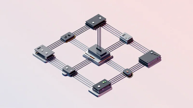
Architectural Evolution for Autonomous Steering
As automotive steering transitions from hydraulic-assisted to fully autonomous steer-by-wire (SbW) systems, PCB design must evolve from simple control modules to high-performance, fault-tolerant compute platforms. The shift requires a departure from legacy centralized architectures toward distributed, domain-controlled topologies that prioritize low-latency data transmission and multi-path redundancy.
Designing for High-Speed Data and Redundancy
Autonomous systems rely on sensor fusion and real-time path planning, necessitating PCBs with advanced high-speed signal integrity (SI) management. Engineers must implement differential pair routing and specialized dielectric materials to accommodate high-frequency communication protocols like Automotive Ethernet, while maintaining strict electromagnetic compatibility (EMC) standards.
| Design Consideration | Legacy Steering | Autonomous SbW |
|---|---|---|
| Redundancy | Single-channel fail-safe | Triple-modular redundancy |
| Signal Speed | Low-speed CAN | Gigabit Ethernet (1000Base-T1) |
| Data Processing | Simple MCU logic | SoC with AI inference |
| Power Delivery | 12V stable | 48V/12V dual-rail architecture |
Frequently Asked Questions
- How does 48V architecture impact PCB selection?
The shift to 48V systems requires PCBs with higher tracking clearances and specialized solder masks to prevent creepage, arcing, and insulation breakdown under high-voltage transients. - Why is thermal management critical for autonomous SbW?
Autonomous steering SoCs generate significant localized heat; future-proofing demands the use of high-Tg (glass transition temperature) laminates and optimized thermal via structures to maintain component longevity. - Is modularity necessary for steering PCBs?
Yes, adopting modular PCB sub-assemblies allows for easier integration of hardware security modules (HSM) and scalable processing power without necessitating a full board redesign as software requirements evolve.
Selecting the right PCB materials and processes is the foundation of automotive safety. By prioritizing thermal stability, high-current capability, and adherence to global manufacturing standards, engineers can build the next generation of reliable steering systems. Ready to optimize your automotive design? Contact our engineering team today to review your board specifications and ensure your components are mission-ready.
