
As modern vehicles evolve into sophisticated sensor platforms, the architecture underpinning safety features is undergoing a massive transformation. The shift from traditional ultrasonic sensors to high-frequency radar-based detection represents more than just a component swap; it mandates a complete rethink of PCB engineering requirements to ensure peak reliability, signal integrity, and manufacturing efficiency.
The Evolution of Detection: Ultrasonic to Radar
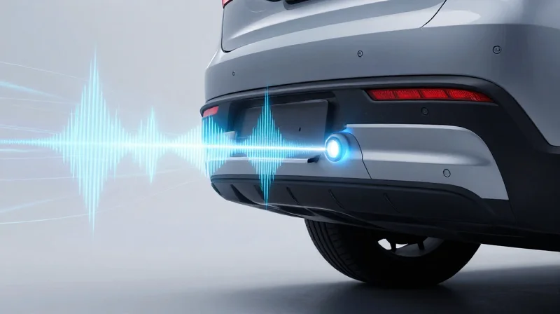
From Acoustics to Electromagnetic Precision
Early automotive safety systems relied heavily on ultrasonic sensors, which functioned by emitting high-frequency sound waves and measuring the time taken for reflections to return. While cost-effective for parking assistance, these systems proved inadequate for high-speed blind spot monitoring due to environmental interference, such as wind noise, road spray, and thermal fluctuations. The industry shift toward radar—specifically millimeter-wave (mmWave) technology—has redefined automotive safety by utilizing electromagnetic waves that maintain consistent performance despite adverse weather or debris.
Comparing Sensing Modalities
| Feature | Ultrasonic Sensors | Radar Systems (77-79 GHz) |
|---|---|---|
| Operating Medium | Acoustic Waves | Electromagnetic Waves |
| Effective Range | Short (up to 3m) | Long (up to 150m+) |
| Weather Resilience | Low (affected by spray/dirt) | High (penetrates fog/rain) |
| Detection Scope | Proximity only | Velocity and distance tracking |
Technical Advantages of Modern Radar
The transition to radar necessitates advanced PCB design capable of handling high-frequency signals with minimal insertion loss and heat dissipation. Modern blind spot detection systems leverage sophisticated Frequency-Modulated Continuous Wave (FMCW) radar to track not only the presence of a vehicle but also its relative velocity, providing critical data to Adaptive Cruise Control and Lane Change Assist modules.
- Why is 77 GHz the industry standard for radar?
The 77-79 GHz frequency band offers a wider bandwidth, which allows for superior range resolution and the ability to distinguish between closely spaced objects. - Does radar replace ultrasonic sensors entirely?
No, ultrasonic sensors remain the standard for low-speed parking assistance, while radar is preferred for mid-to-long-range dynamic object tracking.
The New Engineering Challenges for Automotive PCBs
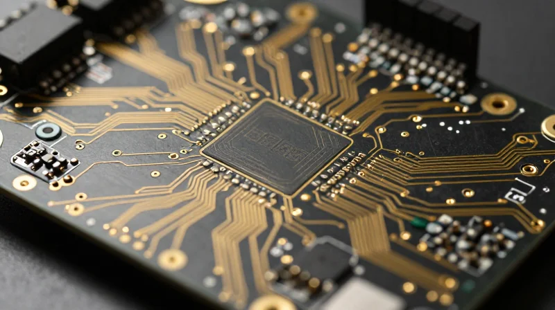
The Challenge of Signal Integrity at 77GHz
As blind spot detection moves toward 77GHz radar sensors, PCB design shifts from standard transmission line theory to complex microwave engineering. Maintaining signal integrity requires ultra-low-loss substrate materials, such as PTFE-based laminates, to minimize insertion loss. Furthermore, the routing of these signals requires precise control of trace impedance and the elimination of discontinuities at via transitions, as even minor manufacturing tolerances can lead to significant signal degradation.
Thermal Management in High-Density Modules
Miniaturized radar modules pack sophisticated processors and monolithic microwave integrated circuits (MMICs) into increasingly smaller footprints. This high power density creates concentrated heat zones that can lead to thermal drift in sensitive analog components, directly impacting detection accuracy. Engineers are now utilizing advanced thermal management techniques, including copper-filled vias, thermal interface materials (TIMs), and direct-to-chassis heat dissipation paths to ensure reliable operation under extreme automotive temperature cycles.
Comparative Analysis of PCB Material Demands
| Parameter | Legacy Systems | Modern Radar Systems |
|---|---|---|
| Substrate Material | Standard FR-4 | High-Frequency PTFE/Ceramic |
| Operating Frequency | < 24 GHz | 77 GHz - 79 GHz |
| Thermal Management | Airflow/Simple Heat Sink | Embedded Thermal Vias/Advanced TIM |
| Trace Tolerances | Moderate | Ultra-Precision/Laser Direct Imaging |
Engineering FAQs for Radar Integration
- Why is standard FR-4 unsuitable for 77GHz radar?
FR-4 exhibits significant dielectric loss and unstable permittivity at microwave frequencies, which causes excessive signal attenuation and impedance mismatch, rendering radar sensing unreliable. - How does PCB miniaturization affect reliability?
Miniaturization increases current density and heat concentration; without advanced materials and effective thermal dissipation, localized overheating can accelerate component aging and induce sensor drift. - What is the primary role of via-in-pad technology in these modules?
Via-in-pad allows for higher routing density and improved electrical performance by reducing trace length between components, which is critical for minimizing parasitic inductance at high frequencies.
Why FR4 Often Falls Short in High-Frequency Applications
The Dielectric Barrier in High-Frequency Design
While FR4 has long been the industry standard for general-purpose electronics, its physical properties become significant liabilities in the gigahertz range required for modern Blind Spot Detection (BSD). The primary limitation is the material's dissipation factor (Df), which measures how much energy is lost as heat as signals propagate through the dielectric.
In 77GHz automotive radar applications, signal attenuation is critical. FR4 exhibits high dielectric loss that increases drastically with frequency, leading to weakened signal integrity and reduced radar sensitivity. Furthermore, its dielectric constant (Dk) is notoriously unstable, fluctuating significantly with temperature and frequency shifts, which destroys the precise impedance control necessary for reliable transceiver performance.
| Parameter | FR4 Substrate | High-Frequency Laminate (PTFE/Ceramic) |
|---|---|---|
| Dissipation Factor (Df) | 0.015 - 0.025 (High Loss) | 0.001 - 0.003 (Low Loss) |
| Dk Stability | Poor (Varies with Temp) | Excellent (Stable) |
| Radar Performance | Inefficient at >24GHz | Optimal for 77GHz |
| Thermal Management | Moderate | Superior |
Impedance Control and Manufacturing Variances
Beyond material composition, FR4 suffers from manufacturing inconsistencies that compromise impedance matching. The fiberglass weave pattern in FR4 can create a 'glass weave effect,' where signal traces experience periodic variations in Dk depending on whether they lie over a resin-rich or fiber-rich area. In radar applications, these micro-variations introduce phase noise and signal reflections, effectively blinding the sensor to subtle object detection movements.
Common Industry Questions on Substrate Migration
- Can FR4 be used for 77GHz radar if the board is thin enough?
No, thin FR4 still possesses high dielectric loss and poor dimensional stability, which prevents the effective transmission of the short-wavelength signals required for high-resolution automotive radar. - Why is thermal stability critical for automotive BSD sensors?
Automotive sensors operate in extreme environments ranging from -40°C to +125°C. The Dk of FR4 shifts significantly across this range, causing 'frequency drift' that can lead to false positives or total failure of the detection system. - Is the cost of high-frequency laminates justified?
Yes, while high-frequency laminates like PTFE or hydrocarbon-ceramic composites cost more than FR4, the reduction in signal loss and enhanced safety reliability make them mandatory for the regulatory and performance standards of modern autonomous driving features.
The Rise of Advanced Ceramic Substrates
Overcoming Thermal and Dielectric Barriers
As automotive radar systems move toward higher frequencies, typically in the 77GHz to 79GHz range, the thermal and electrical limitations of FR4 become apparent. Advanced ceramic substrates, such as Aluminum Nitride (AlN) and Alumina (Al2O3), provide a robust solution by maintaining dimensional stability under extreme temperature fluctuations and offering significantly lower dissipation factors. By effectively dissipating heat generated by high-power MMIC (Monolithic Microwave Integrated Circuit) components, these substrates prevent thermal throttling and ensure the long-term reliability required for mission-critical safety systems.
Performance Comparison: Ceramic vs. Traditional FR4
| Feature | FR4 Substrate | Ceramic Substrate |
|---|---|---|
| Thermal Conductivity | Low (0.25 W/mK) | High (20-180 W/mK) |
| Dielectric Loss (Df) | High (> 0.015) | Very Low (< 0.002) |
| Thermal Expansion | Variable (High CTE) | Stable (Matches Silicon) |
| High Frequency Suitability | Poor (Above 10GHz) | Excellent (Above 60GHz) |
Strategic Advantages in Automotive Radar
The integration of ceramic substrates allows for tighter component integration, facilitating smaller, more powerful blind spot detection modules without compromising safety. Their high thermal conductivity ensures that heat-sensitive radar components remain within optimal operating temperature ranges, extending the lifespan of the safety sensor suite under harsh environmental conditions.
- Why is CTE matching crucial for radar systems?
Ceramics exhibit a Coefficient of Thermal Expansion (CTE) that closely matches semiconductor materials like silicon, preventing solder joint fatigue during the repeated thermal cycling inherent in automotive usage. - How do low dissipation factors impact detection range?
A lower dissipation factor reduces signal energy loss during transmission, resulting in a cleaner signal-to-noise ratio, which directly improves the effective detection distance and resolution of the radar system.
Comparative Analysis: FR4 vs. Ceramic Performance
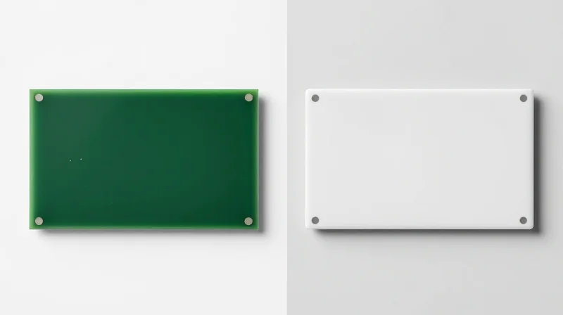
Comparative Performance Metrics
Selecting the appropriate substrate for blind spot detection systems requires a precise balance between signal loss characteristics and long-term environmental robustness. While FR4 remains the industry standard due to its cost-efficiency, its performance degradation at the millimeter-wave frequencies utilized in radar (typically 77-79 GHz) necessitates a transition to high-frequency ceramics or laminate alternatives.
| Feature | FR4 Substrate | Ceramic Substrate |
|---|---|---|
| High-Frequency Loss | High (Significant attenuation) | Low (Excellent signal integrity) |
| Thermal Conductivity | Poor (0.25 W/mK) | Superior (Up to 150+ W/mK) |
| Moisture Absorption | High (Affects dielectric constant) | Negligible |
| Relative Cost | Very Low | High |
Reliability in Harsh Environments
Automotive radar modules are subjected to extreme temperature cycling and humidity variations. Ceramic substrates offer a Coefficient of Thermal Expansion (CTE) that more closely matches silicon-based ICs, significantly reducing mechanical stress on solder joints during rapid heating and cooling cycles. Conversely, FR4's higher CTE and sensitivity to moisture can lead to impedance drift and long-term delamination risks in critical safety-monitoring components.
Frequently Asked Questions
- Can FR4 be used in any radar application?
FR4 is generally unsuitable for 77GHz radar applications due to extreme dielectric loss. It may only be utilized in low-frequency sensing sub-circuits or base-layer power distribution. - Is the cost of ceramic justified for blind spot detection?
For safety-critical systems where signal reliability and environmental longevity are non-negotiable, the higher unit cost of ceramic is justified by significantly lower warranty claims and improved detection accuracy. - Does moisture impact PCB choice?
Yes; FR4 acts like a sponge, absorbing moisture which shifts the dielectric constant and destabilizes radar beam-steering. Ceramics remain inert, ensuring consistent operation regardless of environmental humidity.
Designing for Miniaturization and Integration
Strategies for High-Density Integration
To achieve seamless integration within the confined spaces of modern vehicle bumpers and side mirrors, PCB designers are increasingly adopting High-Density Interconnect (HDI) architectures. By leveraging micro-vias and fine-pitch component placement, designers can significantly reduce the board footprint without compromising the signal integrity required for 77GHz radar processing. The shift towards multi-layer boards with buried vias allows for complex routing in a fraction of the space, ensuring that sophisticated radar circuitry remains hidden within the aerodynamic profile of the vehicle.
Thermal and Space Optimization Techniques
| Optimization Strategy | Primary Benefit | Impact on Miniaturization |
|---|---|---|
| HDI Technology | Increased Routing Density | Reduces PCB surface area by 30-40% |
| Embedded Components | Reduced Z-height | Eliminates surface-mount clearance needs |
| Flexible Circuits | 3D Shape Conformance | Fits radar into non-planar, tight enclosures |
| Advanced Thermal Vias | Localized Heat Dissipation | Enables higher component packing density |
Frequently Asked Questions
- How does miniaturization affect impedance control?
As trace density increases, maintaining consistent impedance requires precise control over dielectric thickness and manufacturing tolerances, often necessitating laser-direct imaging and improved copper etching processes. - Can flexible circuits replace rigid PCBs in radar modules?
Flexible circuits are increasingly used to connect the radar sensor to the main processing unit, allowing the rigid RF front-end to be positioned optimally behind plastic fascias while the main electronics reside in a cooler location. - What is the role of component embedding?
Embedding passive components within the inner layers of the PCB substrate reduces the number of surface-mounted components, effectively shortening signal paths and improving the overall noise immunity of the radar system.
Manufacturing and Reliability Considerations
Manufacturing Scalability and Throughput
To support the massive deployment of blind spot detection systems, manufacturing processes must balance high-precision assembly with high-throughput production lines. Automated Optical Inspection (AOI) and Flying Probe testing have become mandatory to identify micro-fractures in high-frequency laminates that could lead to signal integrity degradation over the vehicle's lifespan.
Reliability under Thermal Stress
Automotive radar modules are subjected to extreme thermal cycling, ranging from freezing temperatures to intense heat generated by both the engine and internal processing components. The following table highlights the impact of material selection on reliability metrics.
| Material Type | Thermal Expansion (CTE) | Long-term Stability | Manufacturing Complexity |
|---|---|---|---|
| Standard FR4 | High | Low | Low |
| High-Tg FR4 | Moderate | Moderate | Moderate |
| PTFE/Ceramic | Low | High | High |
Frequently Asked Questions
- How do we mitigate solder joint fatigue in radar PCBs?
Utilizing advanced underfill materials and optimizing land pad geometries helps distribute mechanical stress caused by disparate CTE values between components and the substrate. - Why is moisture absorption a concern for automotive radar?
Moisture ingress can shift the dielectric constant of the PCB, leading to frequency drift in radar sensors; therefore, low-moisture-uptake substrates are critical for outdoor automotive applications. - What role does surface finish play in high-frequency durability?
Electroless Nickel Immersion Gold (ENIG) or Immersion Silver are preferred to ensure planar surfaces for consistent trace impedance and better resistance to oxidation over a 15-year vehicle lifecycle.
Future Outlook: The Road Toward Autonomous Perception
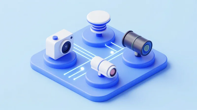
Next-Generation PCB Materials for Sensor Fusion
As blind spot detection (BSD) evolves into full-scale autonomous perception, PCBs must process multi-modal data streams from cameras, LiDAR, and radar simultaneously. This transition necessitates a departure from standard substrate materials toward advanced laminates characterized by ultra-low loss tangents and stable dielectric constants under extreme thermal flux. The industry is shifting focus toward high-frequency, glass-reinforced PTFE laminates that minimize insertion loss at the 77GHz to 79GHz bands, ensuring that raw environmental data is transmitted with zero latency for real-time decision-making.
Comparative Trends in Future Substrate Technology
| Feature | Current Standard (FR4/Hybrid) | Future Outlook (Advanced Laminates) |
|---|---|---|
| Frequency Stability | Variable at high heat | Ultra-stable (Dk/Df optimization) |
| Integration Density | Limited layer count | HDI (High Density Interconnect) |
| Thermal Management | Conventional copper cladding | Metal-core/Thermally conductive resins |
The Convergence of AI and Hardware Architecture
The future of autonomous perception is inextricably linked to on-board hardware acceleration. We are seeing a shift toward 'AI-at-the-edge' architectures, where PCB design now incorporates integrated power delivery networks capable of supporting high-TDP (Thermal Design Power) processing units directly adjacent to sensor arrays. This physical proximity reduces interconnect noise and latency, which are the primary bottlenecks in modern blind spot collision avoidance systems.
Industry Outlook: Frequently Asked Questions
- Why is material selection critical for future sensor fusion?
As bandwidth requirements increase to support high-resolution point clouds from LiDAR and radar, signal integrity becomes the primary barrier to reliability. - Will PCB cost decrease as autonomous systems scale?
While R&D costs are currently high, advancements in liquid crystal polymer (LCP) manufacturing and additive printing processes are expected to drive down costs for high-performance substrates. - What is the biggest hurdle for future PCB reliability?
Maintaining mechanical and electrical stability over 15+ years in harsh automotive environments remains the most significant challenge for next-gen materials.
Transitioning to radar-based detection is essential for the future of vehicle safety, but success hinges on the integrity of your PCB design and material selection. By moving beyond traditional substrates and embracing advanced materials, engineers can meet the rigorous demands of next-generation automotive systems. Ready to optimize your automotive sensor designs? Contact our engineering team today to discuss your next PCB project.
