Printed circuit boards (PCBs) are the backbone of modern electronics, but identifying the tiny components on them can seem daunting. This guide will demystify the world of PCB components, explaining what to look for and providing practical tips for identifying everything from resistors to integrated circuits. Understanding how to identify PCB components is crucial not just for electronics enthusiasts and engineers, but also for anyone curious about how everyday devices work.
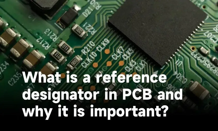
Reference designators are crucial alphanumeric labels printed directly onto a Printed Circuit Board (PCB), acting as unique identifiers for each component. These designators, such as 'R1', 'C2', and 'U3', are not arbitrary; they follow a standardized convention that allows engineers and technicians to quickly locate and identify specific parts. This system of labeling facilitates efficient assembly, testing, and troubleshooting of electronic circuits. Each designator corresponds to a specific type of component, a method that is standardized for consistency. Understanding these identifiers allows for streamlined navigation of complex PCB layouts.
| Reference Designator Prefix | Component Type | Examples |
|---|---|---|
| R | Resistor | R1, R2, R100 |
| C | Capacitor | C1, C5, C23 |
| L | Inductor | L1, L2, L50 |
| D | Diode | D1, D3, D12 |
| Q | Transistor | Q1, Q2, Q15 |
| U | Integrated Circuit (IC) | U1, U4, U20 |
| J | Connector | J1, J2, J10 |
| X | Crystal/Oscillator | X1, X2, X5 |
| SW | Switch | SW1, SW2, SW3 |
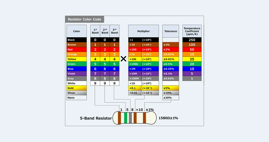
Resistors are fundamental electronic components that impede the flow of electrical current. They are essential for controlling voltage and current levels within circuits. Identifying resistors accurately is crucial for circuit analysis, repair, and design, and this is achieved through a combination of color-coded markings, numerical labels, and package size specifications.
Resistors are primarily identified through three distinct methods: color bands, numerical markings (often for surface mount devices or SMD), and the physical dimensions and markings associated with their packaging type. Each of these methods provides crucial information about the resistor's resistance value, tolerance, and temperature coefficient.
| Identification Method | Description | Key Information |
|---|---|---|
| Color Bands | Axial-lead resistors use colored bands to indicate resistance and tolerance. The position of each band determines its significance. | Resistance value, tolerance, and temperature coefficient |
| Numerical Markings | SMD resistors often use numerical codes or alphanumeric markings. These codes can vary by manufacturer. | Resistance value and sometimes tolerance |
| Package Size and Markings | SMD resistor packages have a specific size and marking code, usually indicating the size. Some packages include value or tolerance codes. | Resistor size and possible value or tolerance codes |
Axial-lead resistors, commonly used in through-hole designs, utilize color bands to indicate their resistance value and tolerance. The standard color code system involves a series of bands, typically four or five, with each color corresponding to a numerical digit, multiplier, or tolerance value. The color sequence is read from one end of the resistor to the other (usually starting with the band closest to the edge). Common color codes include:
SMD resistors use numerical or alphanumeric codes, with the exact marking scheme varying among manufacturers. For instance, a three or four-digit code is often used, where the initial digits indicate the significant figures and the final digit represents the power of ten multiplier. '103' indicates 10 x 10^3 ohms or 10K ohms. Some surface mount resistors may use a letter based code scheme. These may need to be cross referenced against a chart. The physical dimensions of surface-mount resistors are standardized; for example, an '0805' resistor measures 0.08 inch by 0.05 inch and is different from '0603' or other sizes.
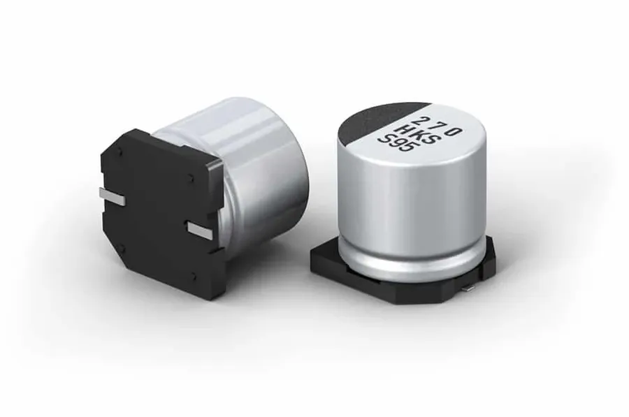
Capacitors are fundamental electronic components that store electrical energy in an electric field. They are characterized by their capacitance value, measured in Farads (F), and come in a variety of types, each with unique characteristics and applications. Understanding how to identify capacitor values and types is critical for proper circuit design and troubleshooting.
| Capacitor Type | Typical Characteristics | Common Applications | Identification |
|---|---|---|---|
| Ceramic | Small, non-polarized, low cost, stable | Bypass, decoupling, general-purpose | Color codes, alphanumeric codes, size |
| Electrolytic | High capacitance, polarized, larger size | Power supply filtering, large energy storage | Value markings, polarity marking, case size |
| Tantalum | High capacitance, small size, polarized, reliable | High-reliability applications, filtering | Value markings, polarity marking, case size |
| Film | Good stability, non-polarized, various shapes | High-frequency applications, precision circuits | Value markings, part numbers, case size |
| Supercapacitor (Ultracapacitor) | Extremely high capacitance, low voltage, very high energy storage | Energy storage in low power circuits and temporary high current applications | Value markings, case size |
Capacitors are marked with alphanumeric codes indicating their capacitance value, voltage rating, and tolerance. These markings can be either printed directly on the component or encoded using a color code (common in older ceramic types). Additionally, surface-mount capacitors typically have an alphanumeric code on them which is decoded using manufacturer specific tables. Electrolytic and tantalum capacitors will also have a polarity marking indicating the correct orientation when placed in a circuit.
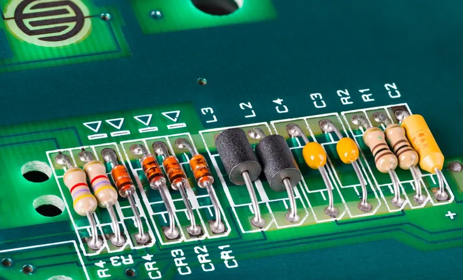
Inductors are fundamental passive components in electronic circuits, primarily used to store energy in a magnetic field when current flows through them. These devices are critical in various applications, including filtering, energy storage, and impedance matching, and are particularly prevalent in circuits handling AC signals. Understanding their physical characteristics and markings is essential for proper identification and usage in electronic design and repair.
The physical appearance of inductors can vary significantly depending on their construction and application. Key features to observe include the core material (ferrite, air, iron), winding geometry (toroidal, solenoid, multilayer), and the presence of a shield or enclosure. Markings on inductors typically denote their inductance value, tolerance, and sometimes a manufacturer's part number. Let's examine the different characteristics in greater detail:
| Feature | Description |
|---|---|
| Core Material | Air, ferrite, iron, etc. Affects magnetic field strength and performance. |
| Winding Type | Toroidal, solenoid, multilayer. Determines inductance, current capability, and physical profile. |
| Shielding | May be present to minimize electromagnetic interference (EMI). |
| Inductance Value | Expressed in Henries (H), millihenries (mH), or microhenries (µH). |
| Tolerance | Indicates allowable deviation from the nominal inductance value. |
| Part Number | Unique identifier assigned by the manufacturer. |
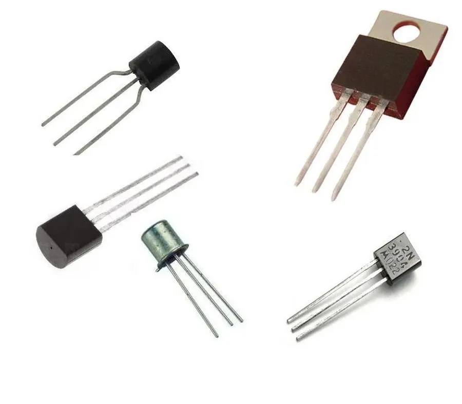
Diodes and transistors are fundamental semiconductor devices crucial for modern electronics, serving distinct but vital functions: diodes primarily allow current flow in one direction, and transistors amplify or switch electronic signals. Correctly identifying these components is essential for understanding circuit behavior and functionality, and is based on a combination of their physical characteristics and component markings.
| Feature | Diodes | Transistors |
|---|---|---|
| Primary Function | Unidirectional current flow (rectification) | Amplification or switching of electronic signals |
| Number of Terminals | Typically two (anode and cathode) | Typically three (base, collector, and emitter for BJT or gate, drain, and source for FET) |
| Physical Appearance | Cylindrical or small rectangular packages with a band indicating cathode, often with a glass or plastic body | Various packages (TO-92, SOT-23, etc.), often with a flat face and distinguishing markings |
| Markings | Often have a part number or band indicating cathode on cylindrical diodes | Usually labeled with a part number, which can be used to look up specifications |
| Typical Applications | Rectification, voltage regulation, signal detection | Amplifiers, switches, signal processing, logic circuits |
| Types | Rectifier diodes, Zener diodes, Schottky diodes, LED diodes | Bipolar Junction Transistors (BJTs), Field-Effect Transistors (FETs), MOSFETs |
Diodes are generally simpler in structure than transistors, usually having two terminals (anode and cathode). The cathode is often indicated by a band or a specific marking on the diode's body. Transistors, being more complex, typically have three terminals, known as the base, collector, and emitter for BJTs or the gate, source, and drain for FETs, and come in various shapes and sizes.
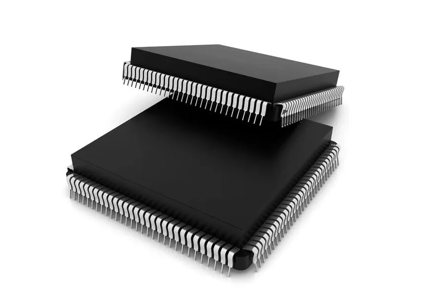
Integrated Circuits (ICs) are fundamental building blocks of modern electronics, incorporating thousands to billions of transistors and other components on a single semiconductor chip. Identifying ICs involves recognizing their package type, deciphering markings, and accessing datasheets to understand their specific functions and pin configurations. These components, often termed the brains of electronic devices, range from simple logic gates to complex microprocessors.
| Package Type | Description | Typical Applications | Identification Features |
|---|---|---|---|
| DIP (Dual In-line Package) | Through-hole package with two parallel rows of pins. | Older designs, prototyping, hobbyist projects. | Two rows of pins, typically rectangular body. |
| SOIC (Small Outline Integrated Circuit) | Surface-mount package with gull-wing leads. | General purpose logic and analog circuits, mass production. | Small, rectangular body with leads extending outward on both sides. |
| QFP (Quad Flat Package) | Surface-mount package with leads on all four sides. | Microcontrollers, FPGAs, complex circuits. | Square or rectangular body with leads on all four sides. |
| BGA (Ball Grid Array) | Surface-mount package with solder balls underneath. | High-density interconnects, complex ICs, processors. | No visible leads; solder balls on the underside of the package. |
| SOT (Small Outline Transistor) | Smaller surface mount packages, can be used for ICs with a small number of pins | Voltage regulation, switching circuits | Various small outlines, generally 3 to 6 leads. |
ICs are typically marked with a part number, often including a manufacturer's logo or name. This information is crucial to accessing datasheets which contain detailed electrical characteristics, pinouts, and application circuits. Manufacturers such as Texas Instruments, Analog Devices, and STMicroelectronics have extensive online resources for accessing IC datasheets. These datasheets are imperative for proper circuit design and application. The markings also usually include date codes and lot numbers for traceability purposes.
To find datasheets, one can search on the manufacturer's website or utilize third-party databases such as Octopart, Mouser, or Digi-Key. The identification process begins by carefully noting the markings on the IC package and using that information to conduct online searches. It is also crucial to note that identical part numbers may have different suffixes indicating different packaging or tolerances, requiring careful data sheet review before use in a design.
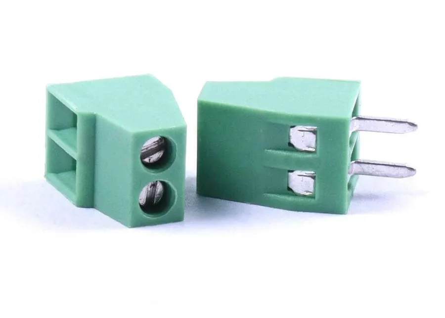
Connectors serve as crucial interfaces within and between electronic circuits, facilitating the transfer of power, signals, and data. Their identification hinges on physical attributes, pin count, and intended application, spanning power delivery, data communication, and various audio/visual interfaces. Understanding the diversity of connector types and their corresponding purposes is essential for proper circuit assembly, maintenance, and troubleshooting.
| Connector Type | Typical Application | Key Identifying Features |
|---|---|---|
| Power Connectors (e.g., DC barrel jack, Molex) | Power supply connection | Robust construction, often polarized (keyed to prevent reverse insertion), various pin configurations. |
| USB Connectors (e.g., Type A, Type B, Type C, Mini/Micro-USB) | Data transfer and power delivery | Distinctive rectangular or oval shapes, varying pin counts and physical sizes, often with a specific logo or markings. |
| Audio Connectors (e.g., 3.5mm jack, RCA, XLR) | Audio signal transmission | Cylindrical or pin-type configurations, specific dimensions according to standard, colour coding for channels (e.g., red and white for stereo RCA). |
| Video Connectors (e.g., HDMI, DisplayPort, VGA) | Video signal transmission | Distinctive shapes with multiple pins or flat conductive contacts, specific markings and configurations based on signal type. |
| Board-to-Board Connectors (e.g., Headers, Pin headers, Card edge connectors) | Internal connections between PCBs | Rows or columns of pins or edge contacts, defined spacing between pins, often come as male and female pairs. |
| Network Connectors (e.g., RJ45) | Ethernet network connection | 8-pin modular connector, distinctive locking tab, specific wiring configurations (T568A/T568B). |
| RF Connectors (e.g., SMA, BNC) | Radio frequency signal transmission | Coaxial cable termination, threaded or bayonet locking mechanism, often have specific impedance characteristics (e.g., 50 ohm). |
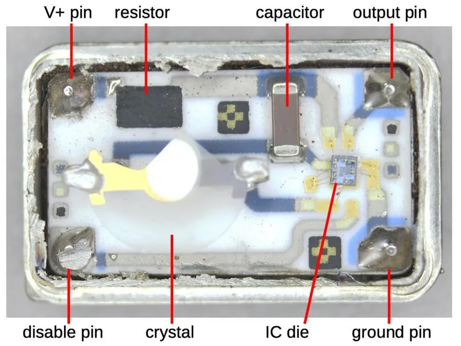
Crystals and oscillators are critical timing components in electronic circuits, providing the stable clock signals necessary for proper digital system operation. Crystals generate a highly precise frequency, while oscillators incorporate active components to produce a clock signal, and they are distinguished by their physical markings and circuit integration.
| Feature | Crystal | Oscillator |
|---|---|---|
| Primary Function | Generates a precise frequency using piezoelectric effect. | Produces a clock signal through active circuitry. |
| Markings | Typically marked with its frequency (e.g., 16 MHz, 32.768 kHz). | May include frequency, part number, and manufacturer information. |
| Circuitry | Requires external circuitry to operate. | Includes internal active components for oscillation. |
| Physical Appearance | Small package with two or more leads. Often has a metal can or ceramic. | Varied package types, often larger than crystals. Includes supporting components or ICs. |
| Stability | Highly stable frequency generation; its temperature dependence needs to be considered. | Output frequency stability dependent on the design, can vary more with temperature. |
| Typical Applications | Microcontrollers, real-time clocks, communication systems, and frequency references. | General purpose clock signals for digital systems. |
Crystals, often housed in small packages with metal cans or ceramic bodies, are marked with their resonant frequency. Oscillators, conversely, may be more complex, with integrated circuits and additional components, and include markings for their operating frequency, model number and manufacturer. While crystals are passive and require external circuitry to oscillate, oscillators actively generate a clock signal. Both are essential for synchronizing digital circuit operations.
This section addresses common queries regarding PCB component identification, offering practical advice and resources to enhance your skills in this area. We aim to provide clear, concise answers that will help you locate datasheets, utilize component search engines, and effectively troubleshoot identification challenges.
Identifying PCB components is a fundamental skill for anyone working with electronics. With a little practice and a keen eye for detail, you can quickly master the techniques discussed in this article. Understanding the reference designators, physical markings, and the roles of different electronic components not only simplifies the process but also opens doors to more advanced troubleshooting and electronics design. By utilizing the techniques in this guide, users can develop a practical and confident approach to identifying PCB components and gain a deeper understanding of electronics.

