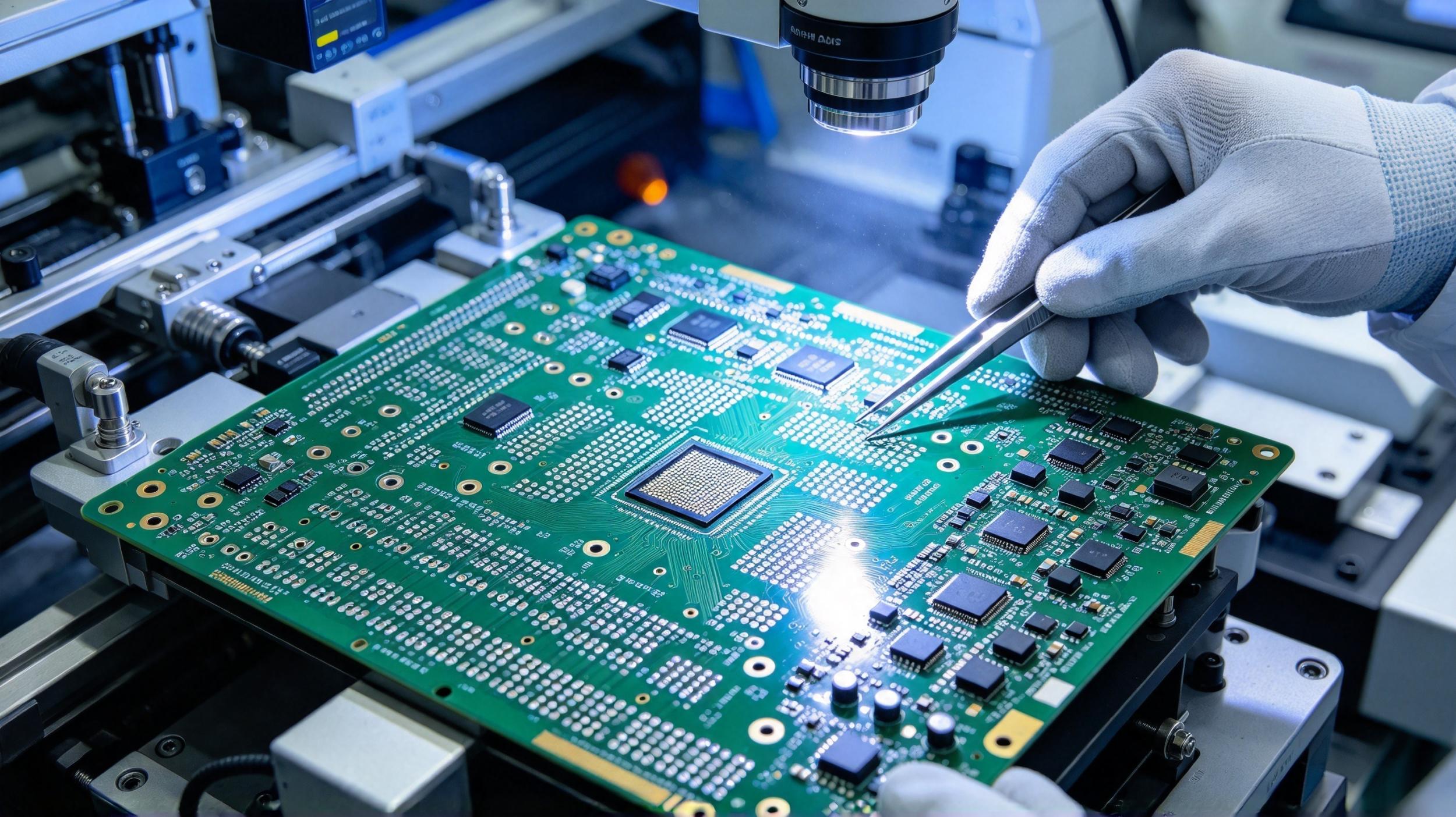
Introduction: High-density interconnect (HDI) PCBs pack more components into smaller spaces using blind vias, buried vias, microvias, via-in-pad, and fine traces. This guide covers HDI design fundamentals, material selection, stack-up planning, via types, sequential lamination, metallization, and manufacturing considerations.
Description: Based on AnyPCBA's small-to-medium volume PCB and PCBA manufacturing experience, this guide explains HDI PCB design basics and manufacturing processes—from material selection and stack-up planning to via formation, sequential lamination, and metallization—and how DFM review catches HDI-specific risks before production.
As technology advances, the demand to integrate more functions into smaller packages continues to grow. PCBs designed with high-density interconnect (HDI) technology are typically smaller, because more components are packed into a smaller space.
HDI PCBs use blind vias, buried vias, microvias, via-in-pad, and very fine traces to concentrate more components into a smaller area. This article covers HDI design fundamentals, manufacturing processes, and the key points from design to production.
High-density interconnect (HDI) PCB design and manufacturing began in the 1980s, when researchers started studying ways to reduce via sizes in PCBs. The first production build-up or sequential printed circuit boards appeared in 1984.
Today, HDI board design and manufacturing are specified in IPC-2315, IPC-2226, IPC-4104, and IPC-6016 standards.
When planning an HDI PCB design, several design and manufacturing challenges must be overcome:
Limited board area
Smaller components and tighter spacing
More components on both sides of the stack-up
Longer routing paths leading to longer signal transmission times
More traces needed to complete the board
HDI manufacturing differs from traditional PCB manufacturing in several simple but important ways.
Core difference: manufacturer limitations constrain design freedom and set routing limits.
Finer traces, smaller vias, more layers, and smaller components can still be accommodated in design software. But meeting design for manufacturing (DFM) requirements depends on the specific manufacturing process and materials used. When reliability requirements are considered, DFM requirements become even more important.
Is the dielectric material chemically compatible with the current core substrate material?
Does the dielectric material provide sufficient adhesion to electroplated copper?
Does the dielectric material provide sufficient and reliable dielectric spacing between metal layers?
Does it meet thermal performance requirements?
Does the dielectric material provide an ideal high glass transition temperature (Tg) for wire bonding and rework?
Can it withstand thermal shock across multiple sequential build-up (SBU) layers?
Can it provide reliable plated microvias?
Dielectric materials used in HDI substrates fall into roughly nine categories, including:
Photosensitive liquid dielectric materials
Photosensitive dry film dielectric materials
Polyimide flexible film
Thermoset dry film
Thermoset liquid dielectric materials
Resin-coated copper (RCC) foil
Traditional FR-4 cores and prepregs
New "spread glass" laser-drillable (LD) prepregs
Thermoplastic plastics
HDI routing efficiency depends on stack-up structure, via structure, component placement, BGA fanout, and design rules. The most important part of planning HDI layout is considering trace width, via size, and BGA component placement/routing avoidance.
When manufacturing HDI PCBs, always confirm the manufacturing method with your PCB manufacturer. You need to determine the limits of their manufacturing method, because this affects the dimensions you can place in layout. BGA ball pitch determines the via size you need, which in turn determines the HDI manufacturing process required.
A typical PCB manufacturing process involves many steps, but HDI PCB manufacturing uses some special steps that may not be used in other boards.
The HDI board design process starts similarly to many others:
Determine the layer count needed to route all signals—using the largest BGA component on the board, or the interface + direction count of the largest IC.
Contact your manufacturer to select materials and obtain dielectric data to create your PCB stack-up.
Based on layer count and thickness, determine the via types used for routing signals through inner layers.
If relevant, perform a reliability assessment to verify the material won't cause stress-induced cracking of interconnects during assembly handling and operation.
Based on manufacturer capabilities and reliability requirements, determine design rules to ensure reliable manufacturing and assembly.
Stack-up creation and design rule determination are the key points, because they determine board routability and final product reliability. Getting this right early helps ensure design reliability, routability, and manufacturability.
Typical via styles used in HDI PCB layout and routing have low aspect ratios, ideally less than 1.
At the center of the PCB stack-up is a conventional buried via, providing connections through thicker core layers. This inner buried via can have a larger aspect ratio because it is machined by mechanical drilling.
Common via types include:
Blind via: starts from the outer layer and penetrates only part of the stack-up
Staggered microvia: microvias arranged in a staggered pattern between layers
Stacked microvia: microvias stacked directly on top of each other
Respecting these microvia aspect ratio limits is an important part of reliability, especially when boards go through reflow soldering or are deployed in environments with repeated thermal/mechanical shock and cycling.
The sequential lamination process is mainly used to build HDI stack-ups layer by layer. This is because high-density, very thin dielectric layers are formed as separate layers around thick core layers, so lamination happens in multiple steps to build the stack-up.
The sequential lamination process includes the following steps:
Photoresist deposition and exposure: defining areas to be etched
Etching and cleaning: the current industry-standard etchant is ferric chloride solution
Via formation and drilling: using mechanical or laser drilling to define vias
Via metallization: metallizing vias to form continuous conductive interconnects
Stack-up build: stacking layers through multiple lamination cycles before outer layer processing
HDI PCBs require interconnects that often reach the minimum via size mechanical drilling can place on a PCB. Once via size drops below 6 mil (about 0.15mm), an alternative via formation process is needed to place microvias between layers.
Because filled and plated microvias are a standard HDI PCB feature, they can be used for via-in-pad design methods, helping increase density. Using via-in-pad is a simple way to accommodate more components in a design, because it provides a direct connection from component pins to inner layers.
When there are concerns about microvia reliability, near-pad technology can also be used—drawing a very short trace segment from the pad to contact the microvia.
During the sequential lamination process, every HDI PCB layer goes through via metallization, filling, and plating. The resulting vias must have no voids inside and sufficient plating wrap around the neck to avoid cracking during reflow cycles and handling.
Four via metallization processes are used in HDI manufacturing:
Conventional electroless and electroplated copper
Conventional conductive graphite or other polymers
Full-additive and semi-additive electroless copper
Conductive paste or conductive ink
Laser drilling is currently the most popular microvia formation process. In laser drilling, a high-energy-density beam is used to drill through the PCB laminate. The laser ablates dielectric material and stops when it hits copper traces, making it ideal for creating depth-controlled blind vias.
As a factory focused on small-to-medium volume PCB and PCBA manufacturing, AnyPCBA has accumulated years of experience in HDI manufacturing.
Our manufacturing capabilities cover 2 to 64 layers, including 1-N, 2-N, 3-N, and any-layer HDI, as well as rigid-flex and high-frequency hybrid. We hold ISO 13485 (medical) and IATF 16949 (automotive) certifications.
In HDI projects, our DFM review focuses on:
Whether the stack-up is manufacturable: confirming layer count, dielectric thickness, and material selection are within factory capability
Whether microvia stacking is feasible: confirming stacked, staggered, and blind via structures are manufacturable
Whether aspect ratios meet reliability requirements: confirming microvia aspect ratios are within the process window
Whether material selection matches the process: confirming dielectric material compatibility with stack-up and plating processes
Whether BGA pitch matches via size: confirming via size meets BGA fanout requirements
Whether impedance control is achievable: confirming stack-up and trace width meet impedance requirements
Our engineers help you confirm these critical details at the design stage, so your HDI boards are not only drawable, but stable and reliable to produce.
If you're working on an HDI project, or want to learn more about our HDI manufacturing capabilities, contact us through our website.




