Mastering LED Circuits: A Comprehensive Guide for Beginners to Experts
2025.01.23
The humble LED, a tiny marvel of light, is ubiquitous in modern life from our phones to our homes. But behind every bright LED is a carefully crafted circuit ensuring its efficient operation. Understanding how an LED circuit works is crucial for any electronics enthusiast. Whether you’re a beginner eager to light your first LED or an expert refining a complex lighting system, this guide will illuminate your path, bridging the gap between theory and practice, and showing how this fascinating technology connects to both our everyday lives and the advancement of social sciences.
Understanding the Fundamentals of LED Circuits
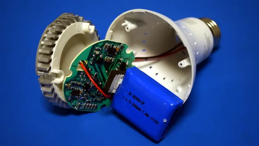
LED Circuit Board
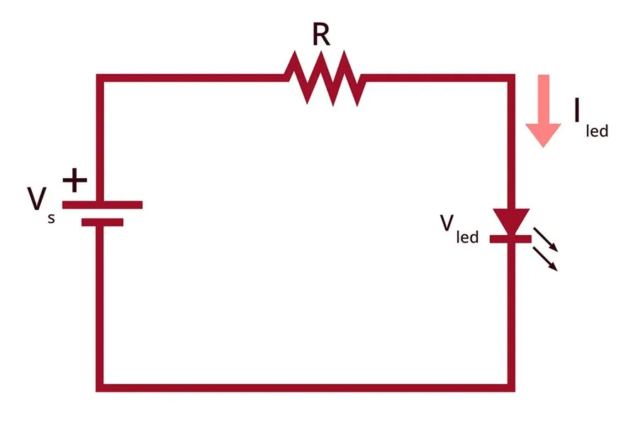
At its core, an LED circuit is a carefully balanced system designed to illuminate a Light Emitting Diode (LED) safely and efficiently. This system primarily includes the LED itself, a voltage source providing the necessary electrical potential, and a current-limiting device, typically a resistor, which regulates the electrical current flowing through the LED. The interplay of voltage, current, and resistance, governed by Ohm's Law (V=IR), is paramount for ensuring optimal performance and long-term reliability of the LED.
LED (Light Emitting Diode): The semiconductor device that emits light when an electric current passes through it. LEDs are characterized by their forward voltage drop and maximum forward current rating.
Voltage Source: Provides the electrical potential necessary to drive the current through the circuit, can be a battery, power supply, or other power source. The voltage source must be chosen to be above the LED's forward voltage.
Current-Limiting Device (Resistor): The component, most often a resistor, which is used to limit the current flow to a safe level for the LED. This is crucial to avoid damage and ensure the LED’s optimal operational life and brightness.
Ohm's Law, a cornerstone of electrical circuit analysis, defines the relationship between voltage (V), current (I), and resistance (R). Specifically, V = IR. In an LED circuit, this means the voltage source (V) drives a current (I) through the LED and the resistor, and the resistor (R) limits the current to avoid damaging the LED. The resistor’s value, therefore, must be selected to safely and efficiently operate the LED, based on the LED's forward voltage and current ratings.
Calculating Resistor Values for LEDs
Resistor in LED Circuit
Determining the correct resistor value is paramount for optimal LED performance and longevity. An incorrectly sized resistor can lead to either insufficient brightness or premature LED failure due to excessive current. This section details the calculations required to select the appropriate resistor, ensuring your LED circuit operates safely and efficiently.
The core principle behind these calculations is Ohm's Law (V = IR), which defines the relationship between voltage (V), current (I), and resistance (R). In an LED circuit, we must calculate the resistance needed to limit the current to the LED's rated specifications.
Parameter
Symbol
Description
Supply Voltage
Vs
The voltage provided by your power source (e.g., battery or power supply).
LED Forward Voltage
Vf
The voltage drop across the LED when it's conducting current. This is a specification provided by the LED manufacturer.
LED Forward Current
If
The recommended current for optimal LED brightness and lifespan, also typically specified by the manufacturer.
Resistor Value
R
The resistance needed to limit the current.
The formula to calculate the required resistance (R) is derived from Ohm's Law and accounts for the voltage drop across the LED: R = (Vs - Vf) / If
Key considerations when using the formula:
Units Ensure all units are consistent: Volts for voltage, Amperes for current, and Ohms for resistance.
LED Datasheet Always refer to the LED's datasheet for its specific forward voltage (Vf) and forward current (If) ratings. These values vary significantly between different LEDs.
Standard Resistor Values Calculated resistance values are rarely standard, so you may have to choose the closest standard resistor value. It's generally better to choose a slightly higher resistance to ensure the LED is within its safe operating range.
Safety Margins It's prudent to add a small safety margin to your resistor calculation. This can help prevent the LED from being overdriven due to minor voltage fluctuations or component tolerances. A good rule of thumb is to slightly increase the calculated resistance value, or use a value that is 5-10% above the calculated value.
Several online calculators can assist in this calculation, and most will require the source voltage, the LED forward voltage, and the desired current.
All About Circuits LED Resistor Calculator A simple and user-friendly calculator that guides you step by step.
DigiKey LED Series Resistor Calculator Provides a slightly more comprehensive calculation including the power dissipation of the resistor.
Basic LED Circuit Configurations: Series and Parallel
LED Parallel Circuit
Understanding series and parallel configurations is crucial for designing effective LED circuits. These configurations impact current distribution, voltage requirements, and overall circuit behavior, directly influencing the performance and reliability of LED lighting systems. Selecting the appropriate configuration is fundamental to achieving the desired lighting effect and preventing premature LED failure.
Characteristic
Series Configuration
Parallel Configuration
Current
Same current through each LED
Current divides among parallel branches
Voltage
Voltage drops across each LED add up to the total applied voltage
Same voltage drop across each LED
LED Failure Impact
Failure of one LED breaks the entire circuit and all LEDs go off
Failure of one LED does not affect the other LEDs
Total Resistance
Total Resistance is the sum of individual resistances
Total Resistance is less than the smallest resistance
Wiring
LEDs are connected end-to-end to form a single loop
LEDs connected side-by-side with common positive and negative rails
Typical use case
Simple circuits with low current requirements and when LEDs must have similar performance
Arrays requiring higher total current with individual LEDs able to function independently
The choice between series and parallel configurations depends heavily on the application’s requirements and available power supply. For instance, if you have a higher voltage power source and need a small number of LEDs, a series circuit might be appropriate. On the other hand, when using low voltage and needing many LEDs, a parallel circuit or a combination of parallel and series circuits might be better. Understanding these distinctions allows for optimized design decisions and efficient LED usage.
Advanced LED Circuit Design Considerations
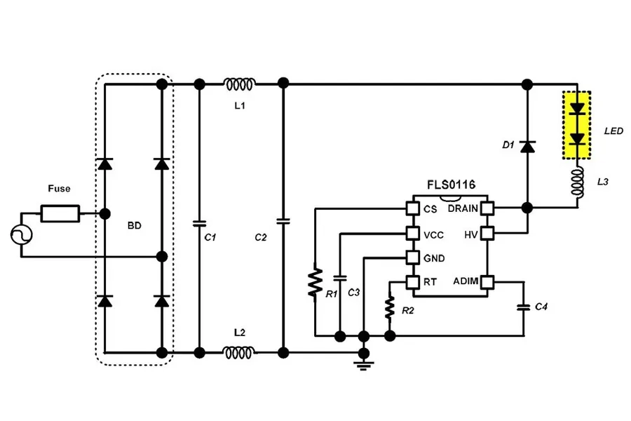
LED Driver IC Circuit
Moving beyond basic LED circuits, advanced design considerations focus on achieving optimal efficiency, control, and longevity for your LEDs. This involves employing techniques such as constant current drivers and pulse-width modulation (PWM) to manage LED brightness and color, ensuring precise performance, and exploring sophisticated control methods to tailor LED behavior.
Specifically, consider the following advanced techniques:
Constant Current Drivers Constant current drivers are essential for maintaining consistent LED brightness and preventing damage. Unlike voltage sources, which can lead to current fluctuations and premature LED failure, constant current drivers regulate the current flowing through the LED, regardless of changes in voltage or temperature. These drivers are particularly useful for high-power LEDs and applications requiring consistent light output.
Pulse-Width Modulation (PWM) PWM is a technique used to control the brightness of LEDs by rapidly switching the current on and off. The duty cycle (the proportion of time the current is on) determines the perceived brightness. This method is energy-efficient and allows for smooth dimming without changing the color characteristics of the LED, and is widely used in digital control systems like Arduino and microcontrollers.
LED Dimming Techniques Dimming LED lighting is crucial in various lighting applications, allowing for dynamic control of light output. Methods include using PWM to dim the light smoothly and consistently without changing color or using analog dimming which adjusts the current through the led, it's important to balance the dimming technique to avoid affecting led lifespan or color consistency.
Color Mixing and Control Circuits Achieving specific colors and dynamic lighting effects requires a deeper approach with control circuits. Color mixing uses multiple LEDs (Red, Green, Blue or RGB) in an array to combine them for a broad spectrum of colors by separately adjusting the intensity of each color. This can be achieve with a microcontroller or specialized IC's. Precision control of multiple LEDs require advanced circuit design and components like transistors or dedicated LED drivers.
Feature
Constant Current Driver
Pulse-Width Modulation (PWM)
Primary Function
Regulates current for consistent LED brightness and protection
Controls LED brightness by adjusting the duty cycle of on/off switching
Impact on LED Lifespan
Prolongs LED lifespan by preventing overcurrent
Efficient for dimming, minimizes wasted energy
Suitability
Best for high-power LEDs, applications with consistent light output
Ideal for dimming applications with digital control systems
Control Method
Direct current regulation
Rapid on-off switching, controlled by duty cycle
Practical Guide to Building a Simple LED Circuit
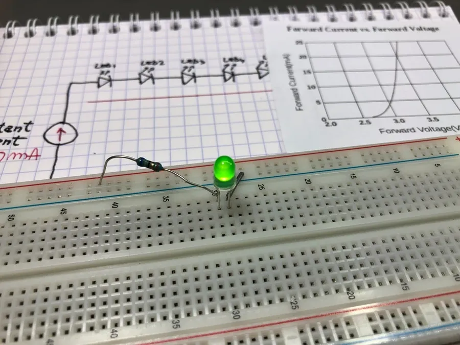
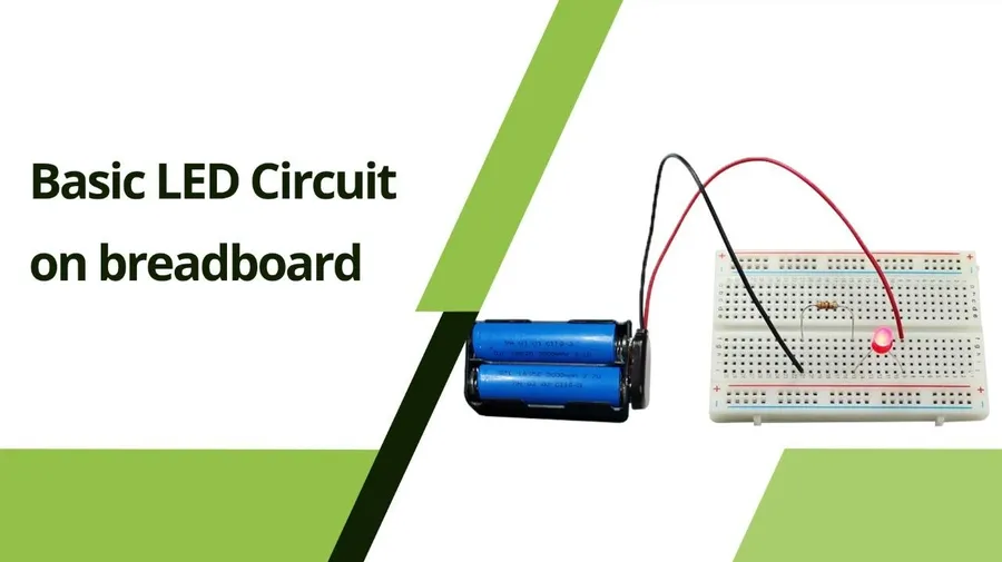
Breadboard LED Circuit
Constructing a basic LED circuit is an excellent hands-on project for grasping fundamental electronics principles. This section details the necessary steps, tools, and materials to build a functional and safe circuit, along with guidance on prototyping to validate your designs effectively.
Required Tools Essential tools include a wire stripper, a set of pliers, and a multimeter for testing. Safety glasses are also highly recommended.
Required Materials Gather an LED (light-emitting diode), a resistor (with the value calculated in the previous section), a power source such as a battery, connecting wires, and a breadboard for prototyping.
Safety Precautions Always ensure that the power source is disconnected before making any changes to the circuit. Be mindful of polarity when connecting the LED (longer lead is positive). Avoid short circuits and never exceed the rated voltage/current limits of the components.
Step 1: Breadboard Setup Place the breadboard on a flat and stable surface, then connect the power source positive terminal to the positive power bus on the breadboard. Similarly connect the ground terminal to the negative power bus of the breadboard.
Step 2: Resistor Connection Connect one lead of the resistor to the positive power bus.
Step 3: LED Connection Connect the other lead of the resistor to one of the rows on the breadboard. Then, connect the positive lead (longer) of the LED to the same row as the resistor and the negative lead (shorter) to a different row.
Step 4: Ground Connection Connect a jumper wire from the negative lead of the LED to the negative power bus on the breadboard.
Step 5: Powering the Circuit Turn on the power source, and observe if the LED illuminates. If not, check the connections and polarity.
Step 6: Testing and Validation Use a multimeter to measure the voltage across the LED and resistor. Compare your results to the theoretical calculations to confirm the correct operation of the circuit. If the LED is not functioning as expected, disconnect power and re-examine connections
Prototyping with a breadboard allows for easy experimentation and troubleshooting without soldering. This practice is essential for validating your circuit design before committing to a more permanent build. By understanding these steps and adhering to safety measures, one can confidently build a working LED circuit.
Troubleshooting Common LED Circuit Problems
Effective troubleshooting of LED circuits is crucial to ensure their reliability and longevity. This section addresses common issues such as LEDs not illuminating, flickering, or experiencing premature failure. We will guide you through diagnostic procedures using essential measurement tools to pinpoint the root causes.
LED Not Lighting Up A non-illuminating LED is often the result of an incomplete circuit or incorrect polarity. First, verify that the circuit is complete with no loose connections. Secondly, ensure that the LED is connected with the correct polarity, as LEDs are diodes and only allow current to flow in one direction. Use a multimeter to check for voltage at the LED terminals, if voltage is present, then consider the LED may be faulty.
Flickering LED LED flickering can stem from several issues including an unstable power supply, a loose connection, or incorrect resistor choice leading to current fluctuations. Check the power supply for consistent voltage output and examine all connections for secure contact. If the power supply and connections are secure, re-evaluate the resistor selection to ensure the LED is properly current-limited, avoiding potential issues caused by voltage or current swings.
Premature LED Failure LEDs, while robust, are sensitive to overcurrent and heat. Premature failure often points to the LED being driven beyond its current rating. Verify the resistor value is correctly calculated for the specific LED's forward voltage and current ratings. Overheating can also cause premature failure, ensure the LED has adequate heat dissipation, especially in high-power applications.
Inconsistent Brightness Inconsistent brightness across multiple LEDs in a circuit may suggest varying current through each LED, or a non-uniform voltage source. This issue can occur in parallel configurations with mismatched LED characteristics or incorrect resistor selections. Check all voltage drops and resistor values using a multimeter, and confirm each LED is receiving the correct current. Re-evaluate your circuit design and resistor values to ensure the LEDs are driven consistently.
Dim LED A dimly lit LED can be attributed to insufficient current flow. This is often caused by an excessively high resistor value or a power supply with low voltage. Verify that the resistor value is appropriate for the intended LED current, and that your voltage source is supplying the required power. If the voltage source is low, you may need to adjust your configuration or replace the source to obtain the correct performance.
Symptom
Possible Causes
Troubleshooting Steps
LED Not Lighting Up
Incomplete circuit, incorrect polarity, faulty LED
Check connections, verify LED polarity, measure voltage at LED terminals, replace LED if necessary
Flickering LED
Unstable power supply, loose connections, improper resistor value
Verify power supply, secure connections, review resistor calculations
Premature LED Failure
Excessive current, overheating
Re-evaluate resistor values, verify current ratings, ensure adequate heat dissipation
Inconsistent Brightness
Varying current through each LED, mismatched LED characteristics
Check all voltage drops and resistor values, ensure consistent current flow
Dim LED
Insufficient current flow, high resistor value
Verify resistor value, check voltage source, adjust configuration
By methodically checking these components and applying the troubleshooting steps described, you can efficiently resolve most common LED circuit issues. Always prioritize safety by ensuring that power is disconnected before any physical changes to your circuit.
Frequently Asked Questions About LED Circuits
This section addresses common queries regarding LED circuits, offering clear, concise, and authoritative answers to enhance your understanding and practical application of LED technology.
What is an LED in a circuit? An LED (Light Emitting Diode) is a semiconductor device that emits light when an electric current flows through it. In a circuit, it functions as a load, converting electrical energy into light. Crucially, LEDs are diodes, meaning they allow current to flow predominantly in one direction. This directional characteristic is fundamental in circuit design, requiring careful attention to polarity.
How do I create an LED light circuit? Creating an LED light circuit involves several key steps: First, choose your LED and determine its forward voltage and current requirements from its datasheet. Next, select a suitable voltage source and calculate the necessary current-limiting resistor to prevent the LED from burning out. Finally, connect these components in series – the positive terminal of your power source to the resistor, then to the anode (longer leg) of the LED, and the cathode (shorter leg) to the negative terminal of your source. Ensure correct polarity of the LED.
How many LEDs can I power on a single circuit? The number of LEDs you can power on a single circuit is primarily determined by the power supply's voltage and current capacity, and the current requirements of each LED. When connecting LEDs in series, the voltage drop across each LED adds up, and the supply voltage must be sufficient to overcome this total voltage. When connecting LEDs in parallel, the total current consumption increases. A key consideration is that it is important to keep the total current draw within the supply capacity of your power source and keep within the maximum current of the components being used.
What are the essential requirements for a basic LED circuit? A basic LED circuit requires an LED, a power source (typically a battery or power supply), and a current-limiting device, usually a resistor. The power source provides the electrical energy. The resistor is crucial to limit the current flowing through the LED to its safe operating range, preventing damage. Correct polarity is essential, where the anode of the LED must be connected to a more positive potential than the cathode.
Why is a resistor needed in an LED circuit? LEDs, unlike incandescent bulbs, exhibit a non-linear current-voltage relationship. Without a current-limiting resistor, a small increase in voltage can cause a large, potentially damaging increase in current, leading to LED failure. A resistor regulates current flow, maintaining it within the LED's specified operational range. This ensures consistent brightness and extends the lifespan of the LED.
Can I connect LEDs directly to a power source? Connecting an LED directly to a power source without a current-limiting resistor is strongly discouraged and will very likely cause the LED to burn out or fail prematurely. LEDs are designed to operate within a very narrow current range; exceeding this can result in rapid device failure, as they do not limit current themselves. Always include a resistor to prevent damage.
What is forward voltage in an LED circuit? Forward voltage is the voltage drop across an LED when current flows through it in the forward direction (anode to cathode). It's a characteristic property of the LED material and is typically specified in the LED's datasheet. This value is critical when calculating the appropriate resistor value for the circuit.
Selecting the Right LED for Your Project
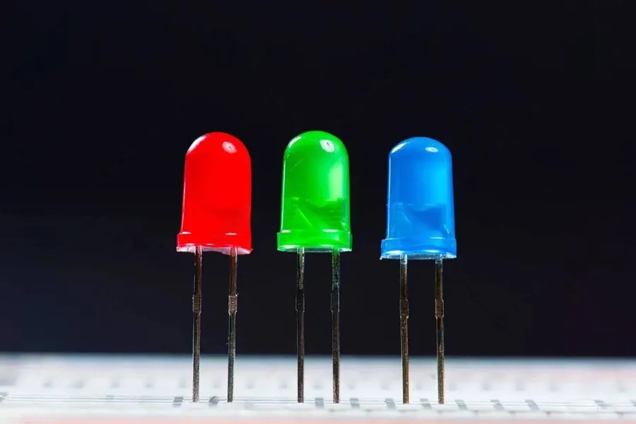
Various LEDs
Choosing the correct LED is crucial for the success of any lighting or electronic project. The optimal LED selection depends on a multitude of factors, including the required brightness, color, physical dimensions, power consumption, and specific application needs. This section details the primary LED types and their characteristics to guide effective LED selection.
LED Type
Description
Key Characteristics
Typical Applications
Through-Hole LEDs
Traditional LEDs with leads that are inserted through holes in a circuit board.
Robust, easy to prototype, larger size, lower cost
Brightness Measured in lumens (lm), select an LED with sufficient brightness for the intended application. Consider the viewing angle, as this impacts perceived brightness.
Color LEDs are available in a wide spectrum of colors and white color temperatures. Choose colors that align with the projects aesthetic and functional requirements (e.g., red for alerts, warm white for ambient lighting).
Size LEDs come in various sizes, from tiny SMD LEDs to larger high-power LEDs. Choose based on spatial constraints and design needs. Consider through-hole sizes for manual projects and SMD sizes for automated assembly.
Power Consumption LEDs are energy-efficient, but the current draw needs to be considered, particularly when using battery power, and consider the need for heat management as power increases. Select LEDs within the thermal limits of the PCB to avoid performance degradation and premature failure.
Mastering LED circuits is a valuable skill for any electronics enthusiast. By understanding the fundamentals, employing effective design strategies, and taking care of practical troubleshooting techniques, you can ensure that your LEDs perform optimally. Whether you’re crafting a simple decorative circuit or a complex lighting system, the knowledge you’ve gained will enhance your ability to bring your creative visions to light, connecting the scientific beauty of led circuit design to practical applications in our society. As LED technology continues to evolve, embracing these principles will empower you to stay at the forefront of innovation and apply these amazing components to real-world and societal applications.