Imagine a world where electronic devices effortlessly control timing, filter signals, and store energy - this is the realm of the humble resistor-capacitor circuit. Like the rhythm section in a band, these components work together to provide the fundamental timing and signal shaping in virtually every electronic device we use daily. From the subtle timing in your phone's display to the smooth transitions in audio equipment, the seemingly simple RC circuit is actually a powerful tool. This article delves into the core principles behind RC circuits, offering a comprehensive understanding for anyone curious about this essential aspect of electronics.
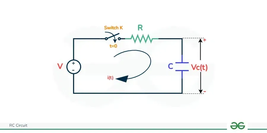
An RC circuit, at its core, is an electronic circuit comprising a resistor (R) and a capacitor (C) interconnected, often with a voltage source. These circuits are fundamental building blocks in electronics, exhibiting time-dependent behavior characterized by the charging and discharging of the capacitor through the resistor. The arrangement of the resistor and capacitor—whether in series or parallel—significantly impacts the circuit's overall response and its suitability for various applications.
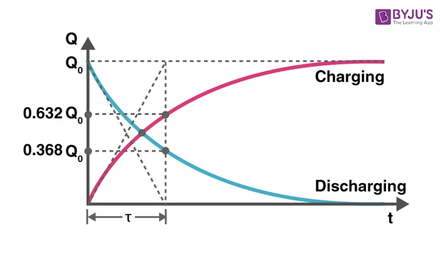
The behavior of an RC circuit is primarily defined by the charging and discharging of the capacitor. These processes are governed by the interplay between the resistor, capacitor, and voltage source, dictating the flow of current and the voltage variations across components over time. Understanding these dynamics is fundamental to grasping RC circuit functionality.
During the charging phase, when a voltage source is connected to the RC circuit, current flows, depositing charge on the capacitor's plates. Initially, the current is at its maximum, limited by the resistor. As charge accumulates, the voltage across the capacitor increases, opposing the source voltage. The rate of charging decreases exponentially as the capacitor voltage approaches the source voltage.
The discharge process begins when the voltage source is disconnected, and the capacitor begins to release its stored charge. The current now flows in the opposite direction, discharging the capacitor through the resistor. The voltage across the capacitor decreases exponentially with time, while the current diminishes simultaneously.
| Parameter | Charging Phase | Discharging Phase |
|---|---|---|
| Current Flow | From source to capacitor | From capacitor through resistor |
| Capacitor Voltage | Increases towards source voltage | Decreases towards zero |
| Current Magnitude | Maximum initially, then decreases exponentially | Maximum initially, then decreases exponentially |
The resistor's primary function in an RC circuit is to control the rate at which the capacitor charges and discharges. A larger resistance value results in slower charge and discharge rates, while a smaller resistance value leads to faster rates. This relationship is critical in many applications where precise timing or signal shaping is required. The time constant, denoted as τ (tau) and calculated as τ = RC, quantitatively describes this rate, with a larger time constant indicating a slower rate and vice versa.
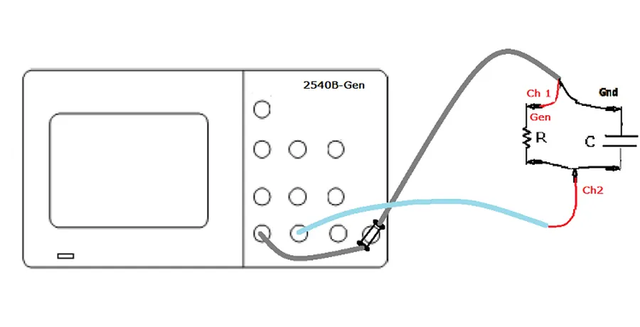
The RC time constant (τ), denoted by the Greek letter tau, is a crucial parameter in understanding the transient behavior of resistor-capacitor (RC) circuits. It represents the time required for the capacitor's voltage or charge to reach approximately 63.2% of its final value during charging, or to decay to about 36.8% of its initial value during discharging. This constant is fundamental in analyzing and designing RC circuits for various applications.
The time constant (τ) is calculated using the formula:
τ = RC
Where: - τ is the time constant in seconds (s) - R is the resistance in ohms (Ω) - C is the capacitance in farads (F)
The time constant (τ) is not just a calculation; it is a practical measure of how quickly an RC circuit responds to changes. A larger time constant indicates a slower charging or discharging process, meaning the capacitor will take longer to reach its final charge or voltage state. Conversely, a smaller time constant means the capacitor will charge or discharge faster.
The significance of the RC time constant extends across various RC circuit applications. For example, in timing circuits, such as those used in flashing lights or delays, the time constant determines the delay time of the circuit. In filter circuits, it plays a role in determining the cutoff frequency, which indicates the frequency at which the filter starts attenuating the input signal.
| RC Time Constant (τ) | Charging Speed | Discharging Speed | Applications |
|---|---|---|---|
| Larger τ | Slower | Slower | Longer delays, lower frequency filters |
| Smaller τ | Faster | Faster | Shorter delays, higher frequency filters |
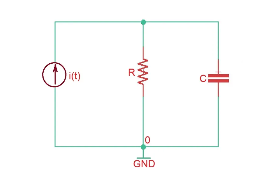
The behavior of a resistor-capacitor (RC) circuit is significantly altered by how its components are interconnected. Specifically, whether the resistor and capacitor are arranged in series or parallel drastically influences the circuit's overall response to applied voltage, particularly concerning charging and discharging characteristics. Understanding these configurations is essential for effective circuit design and application.
| Characteristic | Series RC Circuit | Parallel RC Circuit |
|---|---|---|
| Component Arrangement | Resistor and capacitor are connected end-to-end along a single path. | Resistor and capacitor are connected side-by-side, with both connected directly to the voltage source. |
| Current | Current is the same through both the resistor and capacitor. | Current splits between the resistor and the capacitor branches. |
| Voltage | Total voltage is divided between the resistor and the capacitor; the sum of their individual voltages equals the source voltage. | Voltage is the same across both the resistor and the capacitor, equivalent to the source voltage. |
| Total Resistance | The total resistance is simply the sum of resistances. In a simple RC circuit, this is just the resistance R, as capacitance does not add directly to resistance. However, the resistor’s resistance affects the charging and discharging rates. | The reciprocal of the total resistance is equal to the sum of the reciprocals of the individual resistances. In a simple parallel RC circuit, the capacitor doesn't directly add to total resistance but affects the impedance of the parallel circuit. |
| Total Capacitance | In a series RC circuit, the capacitance of individual capacitors does not directly add. However, the effective behavior of the series capacitor is influenced by the value of the capacitor itself. | The total capacitance is simply the sum of individual capacitances. In a simple RC parallel circuit this is just the single capacitor. |
| Charging/Discharging Time | The time constant (τ = RC) dictates the charging and discharging rate; changes in resistance directly affect the time constant. | The time constant (τ = RC) also dictates the charging and discharging rate; changes in resistance directly affect the time constant. |
| Impedance | The total impedance depends on the frequency of the applied signal and the values of R and C. | The total impedance of the circuit is the combined effect of the resistor and capacitor working in parallel. |
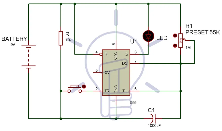
Resistor-capacitor (RC) circuits, fundamental building blocks in electronics, find widespread use across numerous applications due to their time-dependent behavior. Their ability to control the charging and discharging of capacitors enables crucial functions in timing, filtering, and signal processing.
| Application | Circuit Configuration | Function | Examples |
|---|---|---|---|
| Timing Circuits | RC Series | Generate time delays | Blinking LEDs, Clock signals |
| Low-pass Filters | Capacitor in parallel with the output | Pass low frequencies, block high frequencies | Audio amplifiers, Noise reduction |
| High-pass Filters | Capacitor in series with the output | Pass high frequencies, block low frequencies | Pre-amplifiers, DC bias removal |
| Signal Coupling | Capacitor in series | Block DC, Pass AC signals | Multi-stage amplifiers |
| Signal Decoupling | Capacitor to ground | Reduce voltage fluctuations | Power supply stabilization |
| Sample-and-Hold Circuits | RC Series with switch | Sample and Hold voltage values | Data Acquisition |
Analyzing RC circuits involves understanding the relationships between voltage, current, resistance, capacitance, and time. Key formulas enable us to predict circuit behavior during charging and discharging processes, crucial for effective circuit design and analysis.
| Parameter | Charging Formula | Discharging Formula | Description |
|---|---|---|---|
| Capacitor Voltage (Vc) | Vc(t) = V₀(1 - e^(-t/RC)) | Vc(t) = V₀ * e^(-t/RC) | Voltage across the capacitor at time t, where V₀ is the source voltage for charging or initial voltage for discharging. |
| Capacitor Current (Ic) | Ic(t) = (V₀/R) * e^(-t/RC) | Ic(t) = -(V₀/R) * e^(-t/RC) | Current flowing into or out of the capacitor at time t, where V₀ is the source voltage for charging or initial voltage for discharging. |
| Time Constant (τ) | τ = RC | τ = RC | Time required for the voltage or current to reach approximately 63.2% of its final value during charging or to decay to 36.8% of its initial value during discharging. Represents the characteristic response time of the circuit. |
Where:
Tips for using these formulas:

Resistor-capacitor (RC) networks extend the functionality of basic RC circuits by combining multiple resistors and capacitors in various configurations. These networks offer enhanced capabilities in signal processing, noise reduction, and surge protection, making them indispensable in modern electronics.
RC networks are not simply collections of individual components, they act as unified systems with unique properties depending on their configuration. The strategic placement of these components allow engineers to tailor network behaviour to specific needs, resulting in more sophisticated electronic systems.
| Application | Description | Benefit |
|---|---|---|
| Surge Protection | RC networks, particularly snubbers, mitigate voltage spikes by absorbing excess energy. | Protects sensitive components from overvoltage damage. |
| Noise Reduction | RC filters attenuate high-frequency noise, cleaning up signals. | Improves signal clarity and reduces interference. |
| Signal Integrity Maintenance | RC terminations prevent signal reflections and ringing on transmission lines. | Ensures reliable data transfer and reduces signal degradation. |
This section addresses common questions about Resistor-Capacitor (RC) circuits, clarifying fundamental concepts and practical applications. These questions delve into the core behaviors and uses of RC circuits.
Effective troubleshooting of RC circuits requires a systematic approach to identify and rectify common issues. This involves understanding typical failure modes, employing appropriate testing methods, and utilizing practical troubleshooting techniques to ensure optimal circuit functionality.
Resistor-capacitor circuits, while simple in design, form the cornerstone of numerous electronic applications. By understanding their behavior and the impact of the RC time constant, you unlock the ability to design precise timing, signal filtering, and energy storage in circuits. The humble RC circuit demonstrates that a combination of basic components can lead to sophisticated and crucial functions in electronics. The potential applications are vast, from the precise timing in digital clocks to the delicate filtering of signals in audio equipment, the role of the resistor capacitor circuit is critical to our everyday technology. This knowledge forms a strong foundation for deeper exploration into more complex circuit design and applications.

