Imagine a city's traffic system; sometimes cars line up one after the other (like resistors in series), and sometimes they diverge into multiple paths (like resistors in parallel). Understanding how resistors behave in series and parallel configurations is fundamental to electronics design and circuit analysis. This article will demystify these concepts and show you how to calculate equivalent resistances, empowering you to build and understand various circuits.
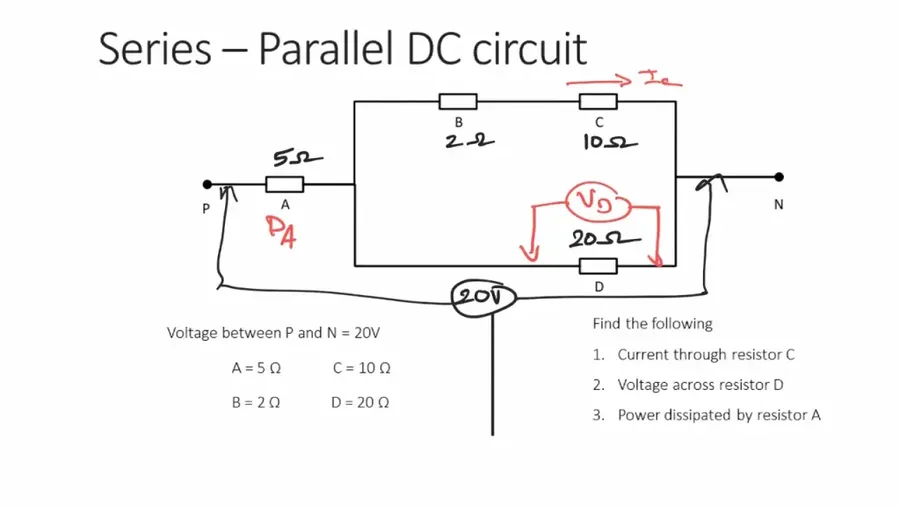
Series and parallel circuits represent the two fundamental ways in which electrical components, particularly resistors, can be connected within a circuit, each configuration exhibiting distinct behaviors regarding current and voltage flow. Understanding these differences is crucial for effective circuit design and analysis.
In a **series circuit**, components are connected end-to-end, forming a single path for current to flow. Consequently, the current remains the same throughout the entire circuit, while the total voltage is divided among the resistors. Visually, imagine a chain where each link is a resistor, the current is analogous to the chain moving as one.
Contrastingly, in a **parallel circuit**, components are connected across each other, creating multiple paths for current flow. Here, the voltage is the same across all parallel branches, while the current divides among the resistors. A parallel circuit can be visualized as multiple lanes on a highway, the total current divides up into each lane.
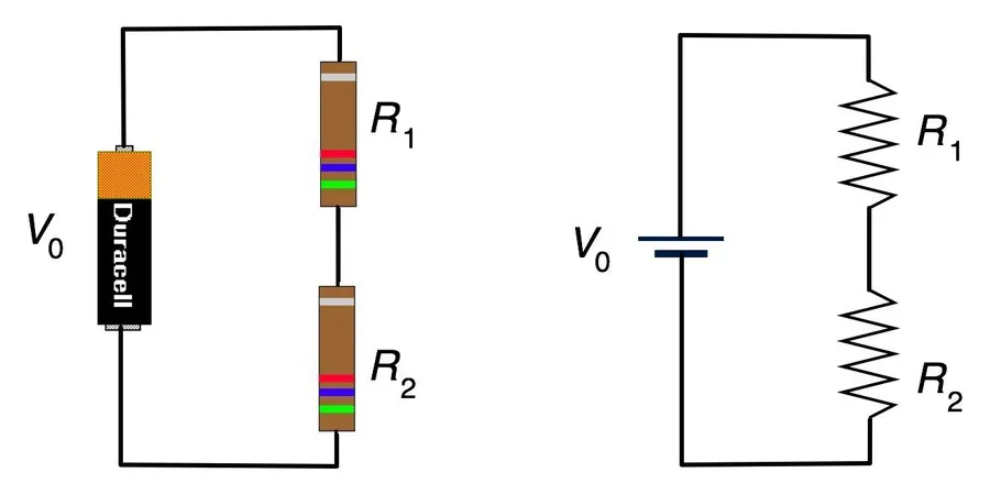
In a series circuit, resistors are connected end-to-end, forming a single path for current to flow. This configuration results in the same current passing through each resistor, while the total voltage is divided across all resistors in the series. Understanding this fundamental principle is critical for analyzing and designing electronic circuits.
Key Characteristics of Series Resistor Circuits:
Real-World Example: Simple String Lights
A classic example of a series circuit is a simple string of holiday lights. Each light bulb acts as a resistor. If one bulb burns out (creating an open circuit), the current path is broken, and all the other lights go out because they share the same current path. This illustrates the interdependence of components within a series circuit.
Mathematical Representation:
R_t = R_1 + R_2 + R_3 + \cdots + R_n
Where R_t is the total series resistance and R_1, R_2, R_3 to R_n are the individual resistances of the resistors in the circuit.
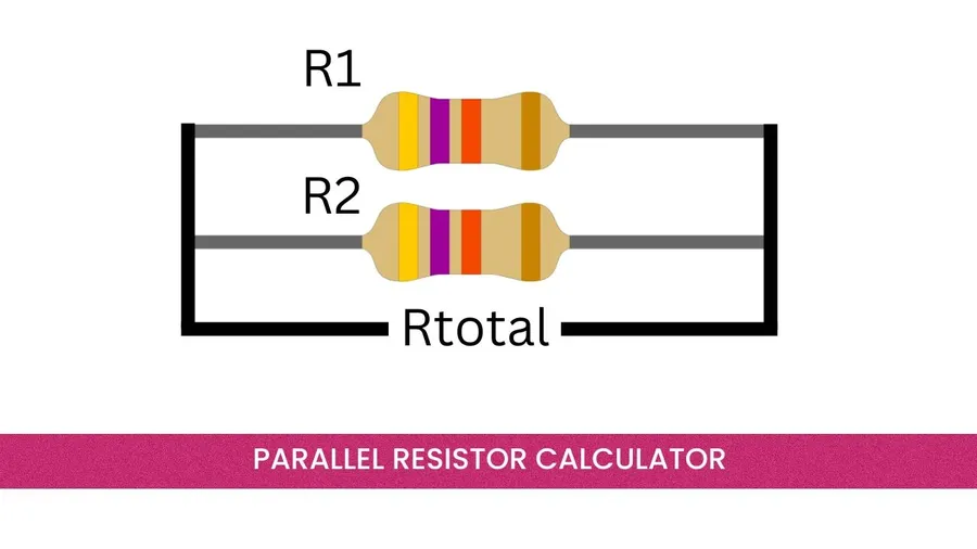
In a parallel circuit, resistors are connected side by side, providing multiple paths for current to flow. This configuration contrasts with series circuits, where there is only a single path for current. A key characteristic of parallel circuits is that the voltage is the same across each resistor, while the total current is divided amongst the branches.
The total resistance of a parallel circuit is always less than the smallest individual resistance, a counterintuitive but crucial property. This is because adding more parallel paths effectively increases the overall ability of the circuit to conduct current. Calculating the total or equivalent resistance requires a reciprocal relationship, with special handling for only two resistors.
The general formula for calculating the total resistance (Rt) of resistors in parallel is given by: 1/Rt = 1/R1 + 1/R2 + 1/R3 + ... , where R1, R2, R3,... are individual resistor values. A simplified equation to calculate the total resistance of two parallel resistors, R1 and R2 is: Rt=R1R2/(R1+R2)
Consider a common application, a multi-bulb lighting fixture. In this case, each bulb acts as a resistor, wired in parallel, if one bulb burns out the remaining bulbs continue to function normally. This is because the voltage remains constant across each bulb, allowing current to flow through other branches, independent of the failed path. The total current is shared between each bulb path, so that current is supplied and the individual bulbs can function normally.
| Characteristic | Description |
|---|---|
| Connection | Resistors connected side by side, providing multiple paths for current. |
| Voltage | Remains constant across each resistor. |
| Current | Total current is divided among the resistors. |
| Total Resistance | Total resistance is always less than the smallest individual resistance. Calculated by 1/Rt = 1/R1 + 1/R2 + 1/R3 + ... or Rt=R1R2/(R1+R2) for two resistors. |
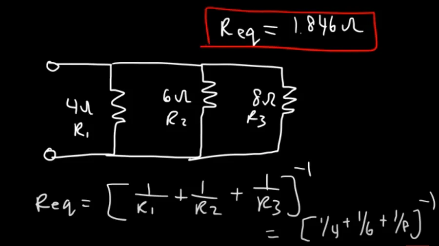
Calculating equivalent resistance is a fundamental technique in circuit analysis, allowing complex networks of resistors to be simplified into a single effective resistance. This simplification is crucial for understanding the overall behavior of a circuit, such as total current flow and voltage distribution, making circuit analysis and design more tractable.
By replacing series or parallel resistor combinations with their equivalent resistance, complex circuits can be reduced to simpler forms. This not only aids in analysis but also provides a practical approach to predict how a circuit will behave under different operating conditions. The equivalent resistance represents the total opposition to current flow that the network of resistors presents to the voltage source.
The process of simplifying complex circuits involves systematically identifying series and parallel resistor configurations. Once identified, the appropriate formulas (Rt = R1 + R2 + ... for series and 1/Rt = 1/R1 + 1/R2 + ... for parallel, or Rt = (R1*R2)/(R1+R2) for two parallel resistors) are applied to derive a single equivalent resistance for each identified network. This process is repeated until the entire network is reduced to a single effective resistor, simplifying subsequent calculations.
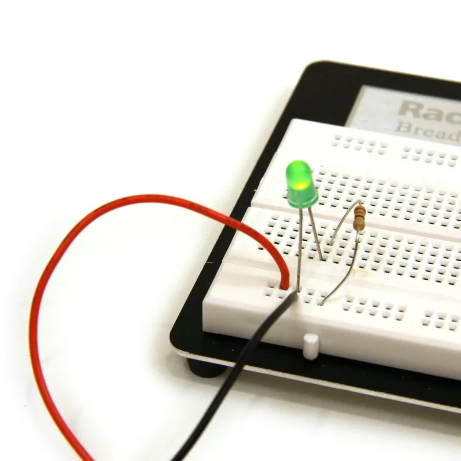
Understanding the fundamental differences between series and parallel circuits is crucial for circuit analysis and design. These configurations dictate how current, voltage, and resistance behave within a circuit, impacting overall functionality. The table below provides a concise comparison of these key characteristics.
| Characteristic | Series Circuit | Parallel Circuit |
|---|---|---|
| Current | Constant throughout the circuit | Divided among branches |
| Voltage | Divided across each resistor | Constant across each branch |
| Total Resistance | Rt = R1 + R2 + R3 + ... | 1/Rt = 1/R1 + 1/R2 + 1/R3 + ... or Rt=R1R2/(R1+R2) for two resistors |
| Failure Mode | Open circuit if one component fails | Other branches remain functional if one component fails |
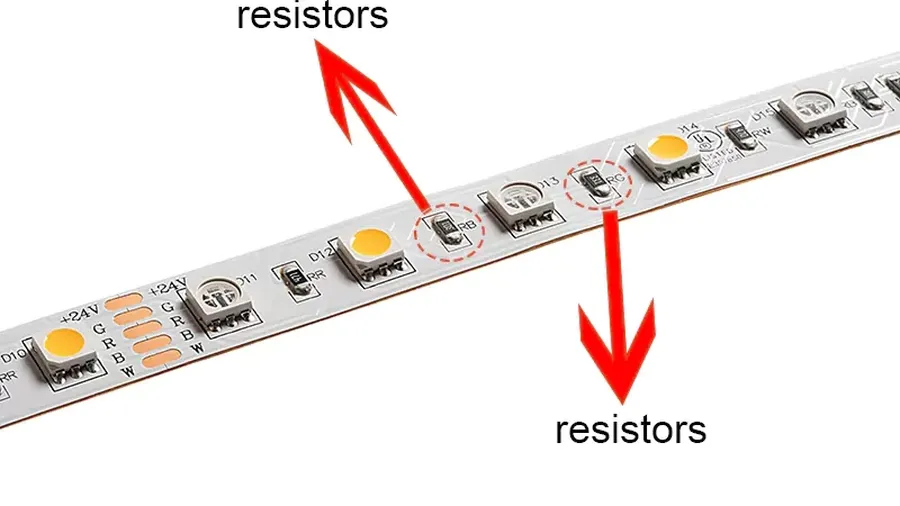
Resistors, when configured in series or parallel arrangements, serve as fundamental building blocks in a wide array of electronic circuits. Their distinct behaviors in each configuration enable engineers to manipulate current and voltage to achieve desired functionalities across various applications.
The combination of series and parallel configurations can be strategically used within the same circuits to achieve more complex objectives. For example, a parallel array of LEDs can be used to increase light output and a series resistor can be added to limit the current.
Understanding the behavior of resistors in series and parallel circuits is fundamental in electronics. This section addresses common questions to solidify your grasp of these concepts, providing clear, concise answers.
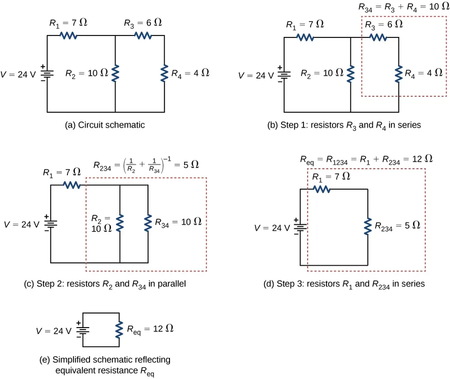
Real-world circuits often feature a combination of both series and parallel resistor configurations, requiring a systematic approach to analyze and simplify them. This section explores how to dissect complex circuits into manageable parts, using equivalent resistance calculations to determine the overall behavior of the network.
The key principle in analyzing these mixed circuits is to work progressively, identifying and simplifying either series or parallel segments before combining the results. This step-by-step process significantly reduces the complexity, allowing for straightforward calculation of the circuit's total resistance and, subsequently, current and voltage distribution.
Consider a circuit where a series combination of a 10-ohm resistor and a 20-ohm resistor is placed in parallel with a 30-ohm resistor. First, the 10-ohm and 20-ohm resistors in series are combined to create a 30-ohm equivalent resistance. Next, this 30-ohm equivalent resistor is in parallel with the 30-ohm parallel resistor. Finally, calculate the equivalent resistance of two 30-ohm resistors in parallel as 15-ohms.
Identifying whether resistors are connected in series or parallel is a crucial skill for circuit analysis and troubleshooting. This section provides practical methods, encompassing both visual inspection and measurement techniques, to accurately determine resistor configurations within a circuit.
Understanding the behavior of resistors in series and parallel is vital for anyone working with electrical circuits. Like carefully managing a network of roads to ensure efficient traffic flow, these concepts allow us to design, control, and troubleshoot electronic devices. By mastering how to calculate total resistances and the differences in current and voltage distributions, you are equipped to tackle a wide range of circuit analysis challenges. Whether it's a simple string of Christmas lights (series) or the complex network of your home's wiring (parallel and combinations thereof), the fundamental principles remain the same. Continuously applying this knowledge is the key to designing innovative and practical electronic solutions.

