In the realm of electronics, just as athletes train to maximize their potential, engineers use capacitors in parallel to boost performance and meet specific energy storage needs. Connecting capacitors in parallel is not just a simple addition; it's a strategic approach to enhance capacitance, manage current, and improve circuit behavior. This article demystifies the concept of capacitors in parallel, providing a clear understanding of their functions, benefits, and calculations.
Capacitors are fundamental electronic components that store electrical energy in an electric field. This ability to store charge, known as capacitance, is measured in farads (F). A capacitor's capacitance determines how much charge it can store for a given voltage, with the relationship being directly proportional; increasing voltage results in a directly proportional increase in charge stored.
The fundamental relationship defining capacitance (C) is expressed as Q = CV, where Q represents the charge stored in coulombs (C), V is the voltage across the capacitor in volts (V). This equation highlights the direct proportionality between charge storage and capacitance at a given voltage.
| Parameter | Symbol | Unit |
|---|---|---|
| Capacitance | C | Farad (F) |
| Charge | Q | Coulomb (C) |
| Voltage | V | Volt (V) |
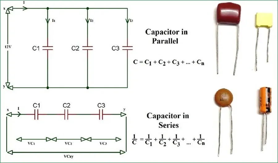
In electrical engineering, 'capacitors in parallel' refers to a specific circuit configuration where multiple capacitors are connected side-by-side, with their respective terminals directly joined. This arrangement ensures that the voltage across each capacitor is identical, as they are all connected to the same two electrical nodes. Understanding this fundamental concept is crucial for designing circuits that require specific capacitance and energy storage characteristics.
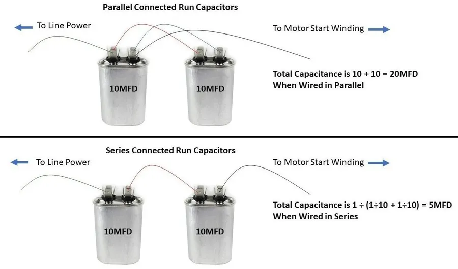
The total capacitance of capacitors connected in parallel is simply the sum of their individual capacitances. This principle arises from the fact that in a parallel configuration, the effective plate area for charge storage increases, thus enhancing the overall capacitance. This is a fundamental concept in electrical engineering, crucial for circuit design and analysis.
The formula to calculate the total capacitance (C_total) of capacitors in parallel is given by:
C_{total} = C_1 + C_2 + C_3 + ... + C_n
Where C1, C2, C3, ..., Cn represent the capacitance of each individual capacitor. This formula is valid regardless of the number of capacitors connected in parallel.
Let's illustrate this with some practical examples:
| Capacitor | Capacitance (F) | Total Capacitance (F) |
|---|---|---|
| C1=1μF, C2=2μF | 1μF, 2μF | 3μF |
| C1=10nF, C2=20nF, C3=30nF | 10nF, 20nF, 30nF | 60nF |
| C1=0.1F, C2=0.2F, C3=0.3F, C4=0.4F | 0.1F, 0.2F, 0.3F, 0.4F | 1F |
Employing multiple capacitors in parallel offers significant advantages over using a single capacitor, particularly in scenarios requiring enhanced capacitance, reduced equivalent series resistance (ESR), and the ability to handle larger currents. This configuration is a fundamental technique in electronics design that allows for performance optimization not achievable with individual components.
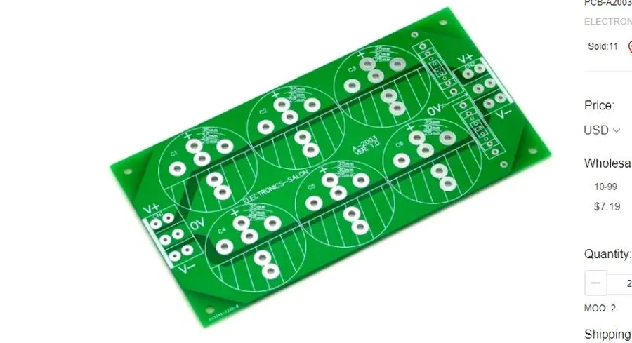
Parallel capacitor configurations are ubiquitous in modern electronics, serving critical roles in various applications by enhancing performance, ensuring stability, and optimizing energy management. These applications leverage the increased total capacitance, reduced equivalent series resistance (ESR), and improved current handling capabilities inherent in parallel capacitor setups.
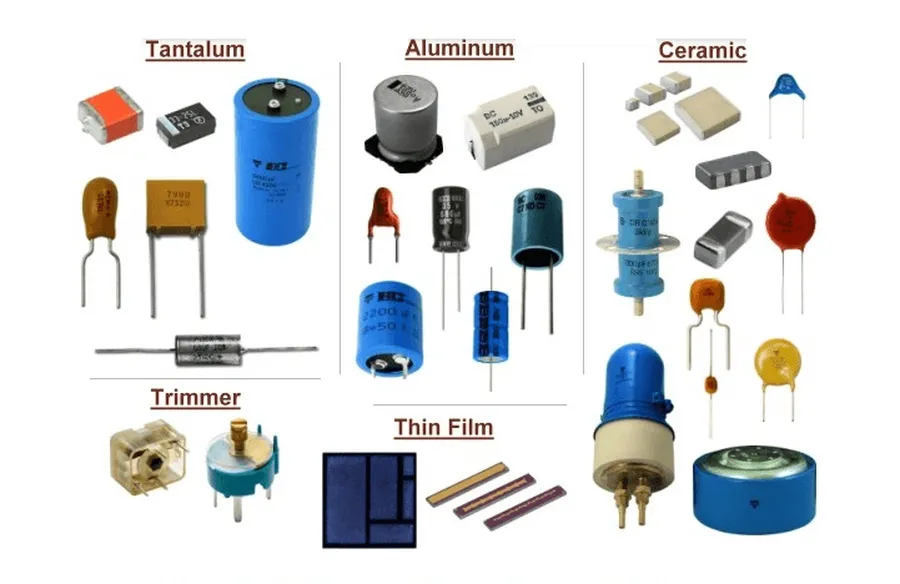
The selection of capacitor type significantly influences the performance of parallel configurations. Different capacitor technologies exhibit unique characteristics, including capacitance stability with temperature and frequency, equivalent series resistance (ESR), and voltage/current handling capabilities, all of which are crucial in parallel circuit applications. Careful consideration of these factors is vital for optimized circuit performance.
| Capacitor Type | Key Characteristics | Suitability for Parallel Use | Considerations |
|---|---|---|---|
| Ceramic | Low ESR, good high-frequency performance, small size, wide range of capacitance values | Excellent for decoupling and high-frequency filtering | Capacitance varies with temperature and voltage, may be prone to piezoelectric effects. |
| Electrolytic | High capacitance per volume, polarized, higher ESR than ceramic | Suitable for bulk energy storage and low frequency applications where high capacitance is required. | Polarity must be observed, limited frequency range, and potential for electrolyte leakage or drying over time. |
| Film | Good stability, low ESR, high voltage ratings, moderate capacitance range | Excellent choice for power applications and timing circuits where stability is paramount. | Larger size compared to ceramic capacitors, more expensive. |
When implementing capacitors in parallel, ensure that the individual components have matched voltage ratings, temperature coefficients, and appropriate ESR ratings for the specific use case. This ensures that the load is evenly distributed across the multiple capacitors.
This section addresses common queries regarding capacitors connected in parallel, providing clear and concise answers to enhance understanding of their behavior and application.
Connecting capacitors in parallel offers several benefits, primarily increasing the overall capacitance of a circuit, which is crucial for energy storage and filtering applications. However, this configuration also introduces certain drawbacks, particularly concerning circuit complexity. It's essential to weigh these factors carefully when designing electronic systems.
| Feature | Advantages | Disadvantages |
|---|---|---|
| Total Capacitance | Increases the total capacitance by the sum of the individual capacitor values. | Requires more physical space for multiple components. |
| Equivalent Series Resistance (ESR) | Reduces overall ESR, leading to lower losses and improved high-frequency performance. | Increased physical circuit complexity, can impact manufacturing costs and reliability. |
| Current Handling | Increases the capacity to handle larger currents compared to a single capacitor. | Capacitor variations due to manufacturing tolerance can result in uneven current sharing |
| Cost | Can use smaller, lower-cost capacitors to achieve higher capacitance compared to using single large capacitor. | Potentially higher component count can lead to increased circuit footprint and assembly costs. |
| Reliability | Potential for redundancy; failure of one capacitor may not cause complete circuit failure. | Individual capacitor failure can impact overall circuit performance. |
When considering parallel configurations, careful selection of capacitor types and values is essential to maximize the benefits and avoid the disadvantages. It's also crucial to take into account the manufacturing tolerances of the capacitors; uneven capacitance values or manufacturing variations can impact performance.
In practical applications, you might use parallel capacitors for increased capacitance in power supply filtering, where the increased capacitance is needed for filtering ripple or in decoupling applications to improve signal integrity by handling transient currents. Consider alternatives like supercapacitors if very high capacitance is needed in a small area and series configurations if high voltage is required.
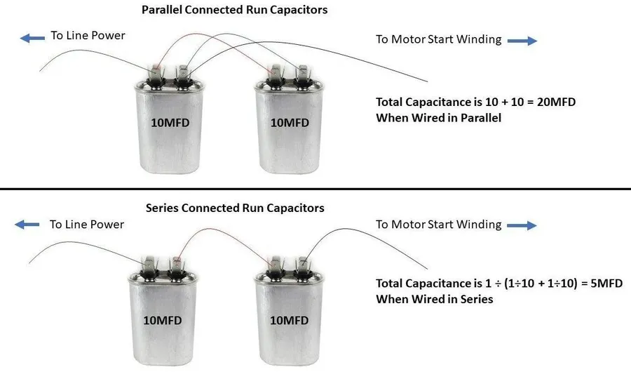
Understanding the distinctions between parallel and series capacitor configurations is crucial for effective circuit design. While parallel configurations increase total capacitance and current handling capabilities, series configurations are used to handle higher voltages. This section provides a comparative analysis of these two common arrangements, detailing their key differences in terms of total capacitance, voltage handling, and suitable application areas.
| Feature | Parallel Capacitors | Series Capacitors |
|---|---|---|
| Total Capacitance | Sum of individual capacitances (C_total = C1 + C2 + ... + Cn) | Reciprocal of the sum of reciprocal capacitances (1/C_total = 1/C1 + 1/C2 + ... + 1/Cn) |
| Voltage Handling | Voltage across each capacitor is the same as the source voltage. | Voltage is divided among the capacitors based on their capacitance. |
| Current Handling | Total current is divided among the capacitors | Current is the same through all capacitors |
| Application Areas | Increasing capacitance, smoothing voltage in power supplies, decoupling in digital circuits. | Voltage multiplication, high voltage applications |
| Equivalent Series Resistance (ESR) | ESR is reduced, improving high-frequency performance | ESR increases, which can be a disadvantage in some applications |
Capacitors in parallel are essential in modern electronics, offering a way to increase capacitance and manage high currents. By connecting capacitors in parallel, engineers can optimize circuit performance and meet the demands of various applications, much like how using multiple instruments can enrich the sound of a band. Understanding these parallel configurations is crucial for designing efficient and reliable electronic systems, and as technology advances, further explorations of parallel capacitor networks promise to enhance future innovations. The ability to precisely tailor capacitor networks using parallel configuration is a testament to the power and flexibility of foundational electrical engineering principles.

