Have you ever wondered how a light switch works or how your phone charger powers up your device? At the heart of these technologies lies the concept of a simple circuit. A simple circuit is the foundation of all electrical and electronic devices, and it's based on a flow of electrical current through a conductive path. In this article, we will demystify the world of simple circuits, and will explore the core components, basic designs, and common examples, all while making the topic both understandable and engaging.
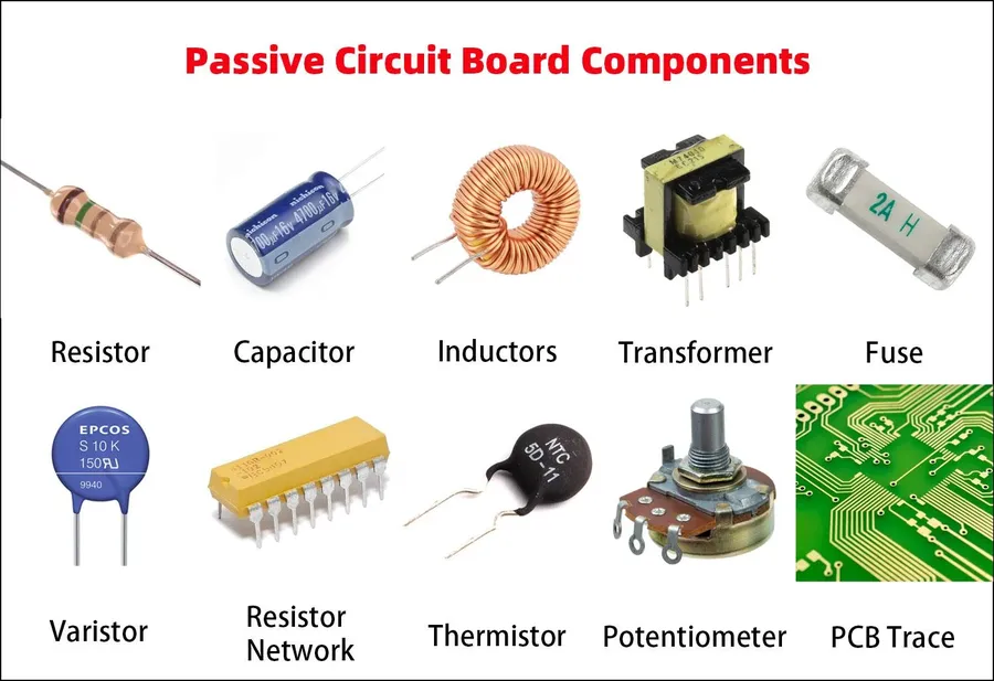
A simple circuit is an electrical pathway that allows for the flow of electrical current. It fundamentally requires three essential components: a voltage source to provide the energy, a conductive path to facilitate the current flow, and a load or resistor to utilize or impede that flow. The behavior of electrical current within a simple circuit can be effectively understood through the analogy of water flowing through a pipe, where voltage is akin to water pressure, current is like the rate of water flow, and resistance is analogous to the pipe's diameter or any constrictions.
In essence, a simple circuit is a complete loop that allows electrons to travel from the voltage source, through the conductive path, and into the load. This loop must be continuous for the circuit to function properly; a break or interruption will halt the current flow. The ability to control and understand the flow of electricity in such a pathway forms the core of the study of basic electronics and electrical engineering.
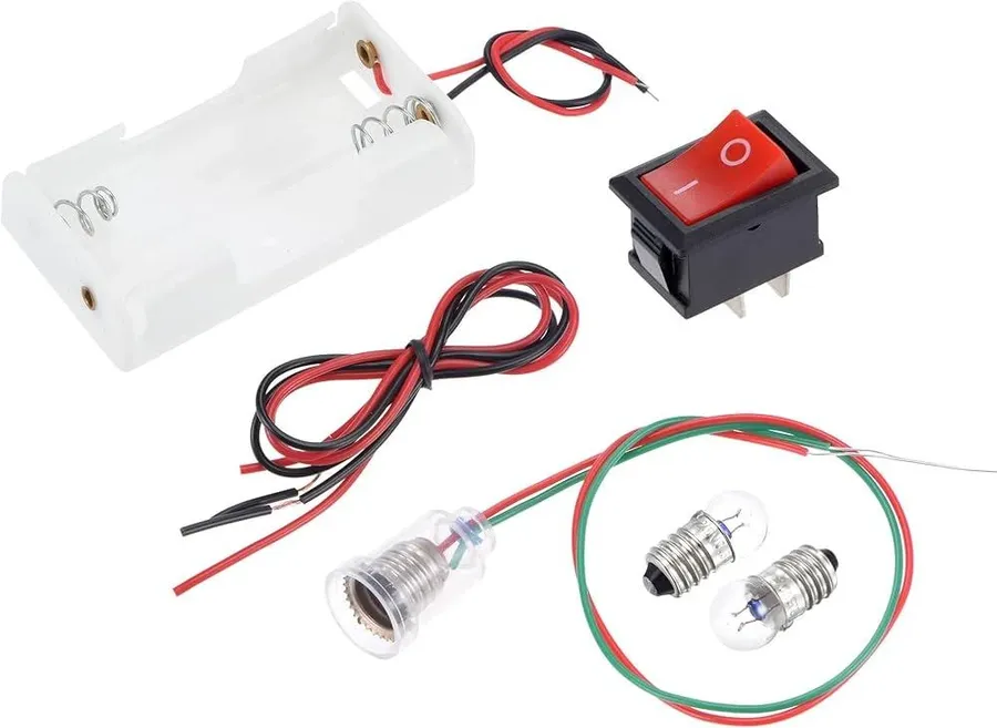
A simple circuit is comprised of three essential components: a voltage source, which provides the electrical energy; conductors, which create a pathway for the current; and a load or resistor, which uses or impedes the flow of current. Understanding these components and their interplay is fundamental to comprehending circuit behavior.
| Component | Description | Role in Circuit | Examples |
|---|---|---|---|
| Voltage Source | Provides the electrical potential difference to drive current. | Acts as the energy pump for the circuit. | Batteries, power supplies |
| Conductors | Materials that allow current to flow with minimal resistance. | Create a path for current to move through the circuit. | Copper wires, metal traces on circuit boards |
| Resistor (Load) | Components that impede or regulate the flow of current. | Consumes energy or provides a specific resistance value in the circuit. | Light bulbs, LEDs, heating elements |
These three components must be connected in a closed loop for current to flow. The voltage source creates the 'push,' the conductors provide the path, and the resistor controls the rate of flow, converting electrical energy into another form. The absence of any component or an open path will break the circuit and stop the current flow.
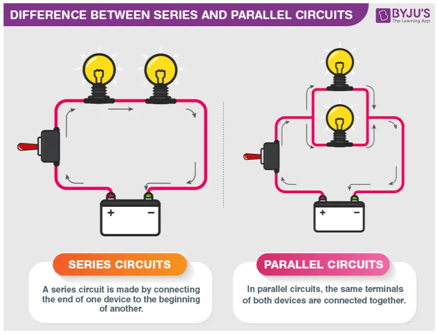
Simple circuits can be categorized into two fundamental types: series and parallel. These configurations dictate how components are connected, which, in turn, profoundly impacts current flow, voltage distribution, and the overall behavior of the circuit. Understanding these differences is crucial for effective circuit design and analysis.
| Feature | Series Circuit | Parallel Circuit |
|---|---|---|
| Current Flow | Same current through all components | Current divides among branches |
| Voltage Distribution | Voltage is divided among components | Same voltage across all branches |
| Total Resistance | Total resistance is the sum of individual resistances (R1 + R2 + ...) | Total resistance is less than the smallest individual resistance (1/Rt = 1/R1 + 1/R2 + ...) |
| Component Failure Effect | If one component fails, the entire circuit breaks | If one component fails, the other branches still function |
| Practical Application | Used in simple circuits where components must function in sequence, such as Christmas lights | Commonly used in household wiring, car electrical systems, and electronic circuits where multiple components operate independently. |
In a **series circuit**, components are connected one after another along a single path. This means that the same amount of current flows through each component. However, the voltage provided by the source is divided among the components. The total resistance of the circuit is the sum of the resistances of each component. A key disadvantage of a series circuit is that if one component fails, the circuit is broken, and the entire circuit stops working.
Conversely, in a **parallel circuit**, components are connected across multiple paths. This arrangement results in the same voltage being applied across each component. The total current from the source is divided amongst these paths. The total resistance of a parallel circuit is less than the smallest resistance in the circuit. A significant advantage of parallel circuits is that the failure of one component does not disrupt the other paths; the circuit continues to function.
Understanding the distinct characteristics of series and parallel circuits is crucial for practical circuit design. These basic configurations serve as the foundation for more complex electrical systems. The choice between series and parallel depends on the specific application requirements, such as the need for consistent current, voltage distribution, or redundancy.
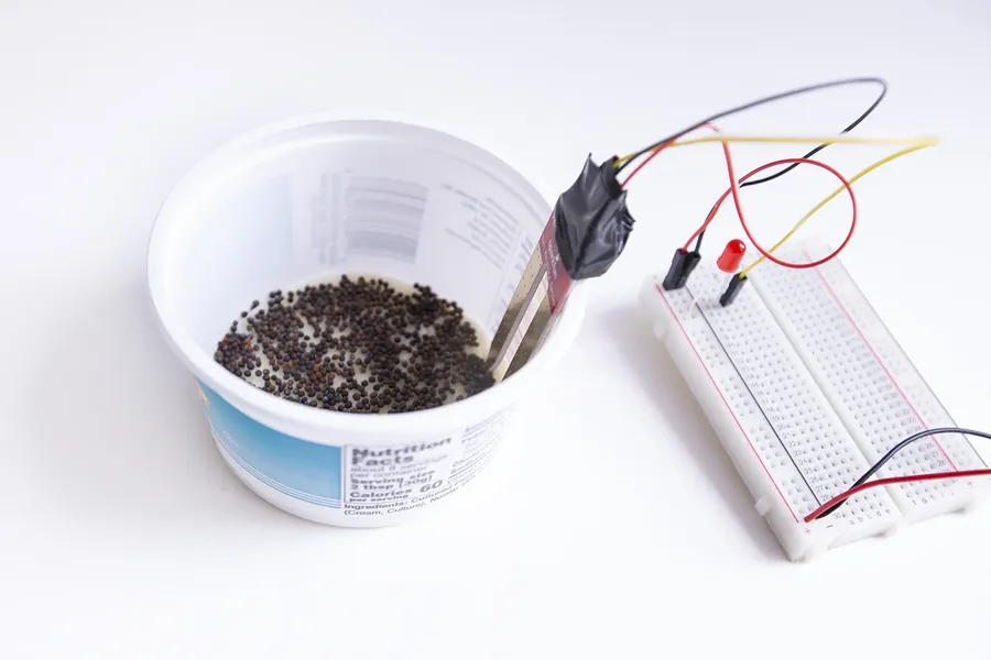
Constructing a basic circuit is a foundational skill in electronics, allowing for a practical understanding of electrical principles. This section provides a detailed, step-by-step guide for building a simple circuit using readily available components, emphasizing safety and offering troubleshooting advice.
Safety Precautions: Always use batteries with voltage ratings within safe operating ranges for all components used. Never connect a battery directly without a load (like a light bulb or LED), or a resistor. This could create a short circuit. Avoid contact with bare wires while the circuit is energized and always disconnect the power source when making changes to the circuit. Supervise children and new learners when building simple circuits.
Troubleshooting Tips: If the light does not illuminate, double-check the battery polarity, wire connections, and the load to ensure proper connections are made. Verify all components function individually. If using LEDs, always use a series resistor to avoid damage, and make sure the leads are the correct way round. Always ensure all connections are secure.
Simple circuit diagrams use symbols to visually represent the components and their interconnections, like a map for your electrical circuit. We will explore this in the next chapter.
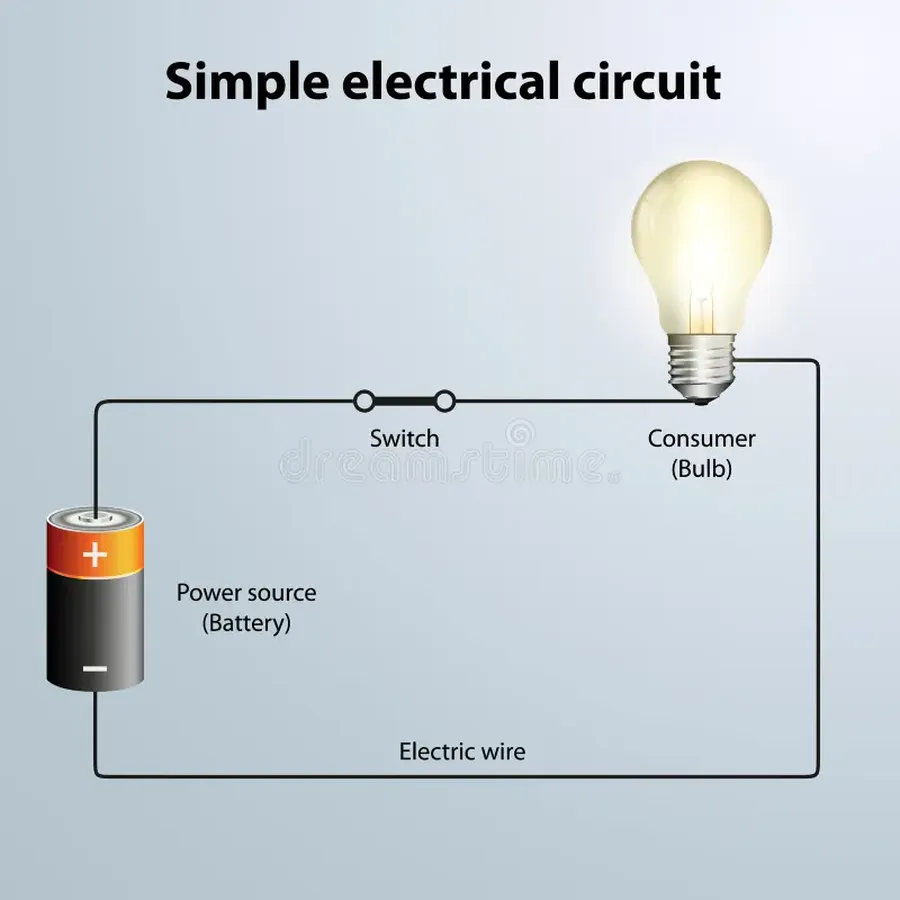
Understanding circuit diagrams is crucial for building and troubleshooting electronic circuits. These diagrams use standardized symbols to represent components, allowing engineers and hobbyists to communicate and construct circuits effectively. This section will introduce common symbols and explain how to interpret them to build real-world circuits, also providing a range of sample circuit diagrams.
A simple circuit diagram is a symbolic representation of an electrical circuit. Instead of drawing components as they physically appear, diagrams use standardized symbols to represent each element. This method simplifies the process of visualizing and constructing circuits, making it easier for anyone familiar with these symbols to understand the circuit's function and layout.
| Component | Symbol | Description |
|---|---|---|
| Battery | A combination of long and short parallel lines | Provides a voltage source. |
| Resistor | A jagged line or a rectangle | Limits current flow. |
| Capacitor | Two parallel lines, one may be curved | Stores electrical charge. |
| Light Bulb | A circle with a cross inside or a stylized light bulb | Indicates the load that is using electrical power and often producing light. |
| LED | A triangle pointing at a bar with an arrowed line | A diode that emits light when current passes through it |
| Switch | A break in a line with a movable arm | Opens or closes the circuit. |
| Wire | A straight line | Connects components, providing a path for current. |
| Ground | Three lines of decreasing length connected to a single line | Reference point of zero potential. |
Reading a simple circuit diagram involves understanding how these symbols are interconnected. Each line represents a wire, and the components are placed along these lines. The path the line takes indicates the current flow path. When the lines form a continuous loop, that suggests the circuit is closed and the current can flow through all components from the voltage source to ground or back to the source.
Diagrams are not only used for the design and construction of circuits but also to explain how they function. By tracing the connections and identifying each component, one can determine the relationship between voltage, current, and resistance within the circuit. This understanding is essential for both creating new circuits and for fixing existing ones.
Here are some sample circuit diagrams:
A simple series circuit with a battery, switch, and a light bulb.
A simple parallel circuit with a battery, switch, and two light bulbs.
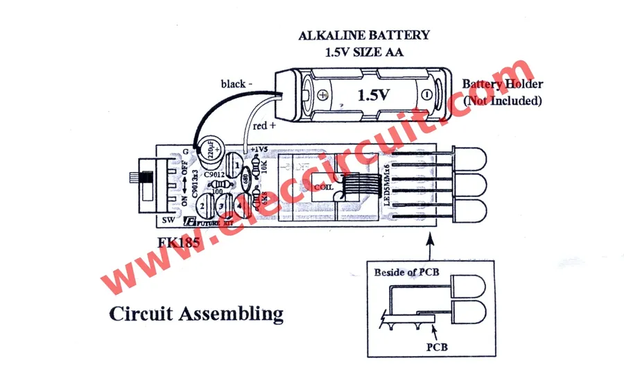
Simple circuits, though fundamental, are ubiquitous in our daily lives, powering a variety of devices we often take for granted. Understanding these basic implementations provides insight into the broader world of electronics. Devices such as flashlights, basic home lighting systems, and simple electronic toys all rely on the principles of basic circuitry.
In each of these examples, the core principle of a closed loop is observed, ensuring electrical current can flow uninterrupted from the power source through the conductive path and the load before returning to the power source. These simple examples highlight the fundamental nature of simple circuits in our daily lives.
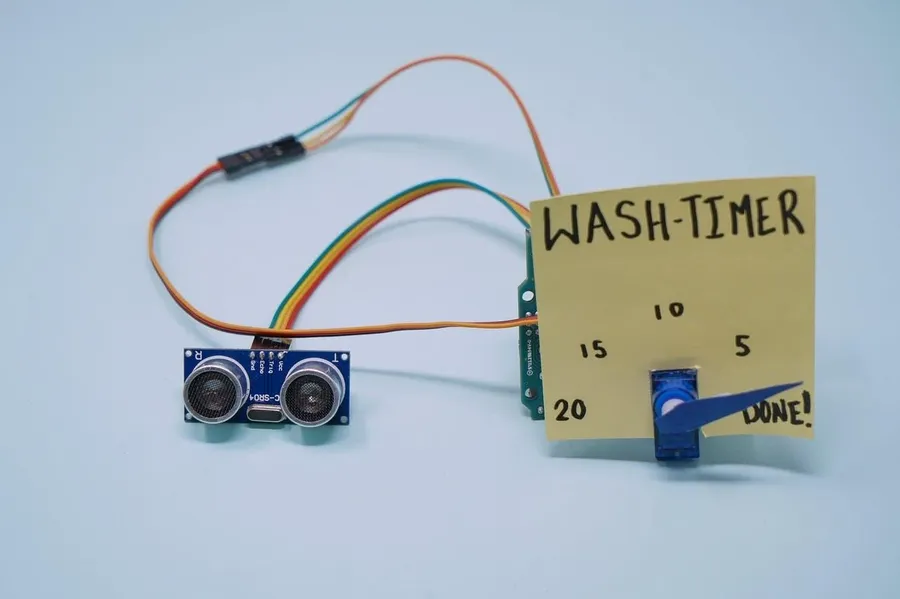
Diving into hands-on projects is an excellent way to solidify understanding of simple circuits. This section presents several beginner-friendly projects that demonstrate practical applications of the concepts discussed earlier. These projects utilize readily available components and offer a tangible learning experience.
These projects serve as foundational experiences. It's crucial to exercise caution when working with circuits, particularly with batteries and electrical components, and to always double-check circuit diagrams before connecting components. Begin with the simplest project such as the LED circuit and progress to other projects only after gaining confidence. Each project provides a unique learning experience, reinforcing theoretical knowledge with practical implementation.
This section addresses common queries regarding simple circuits, providing concise and authoritative answers to help clarify key concepts and applications.
Understanding simple circuits is a gateway to grasping more complex electronics. By grasping these basic principles and building simple projects, you can build a foundation for more advanced electronics and circuits and start to appreciate how our daily devices work. The journey begins with these small, simple circuits, which form the foundations of the technology around us and power our modern world. Consider your ability to now create a simple circuit - a light from a simple battery. You’ve got the power!

