
As automotive lighting shifts toward high-intensity LED architectures, heat management has evolved from a secondary concern to a critical engineering imperative. For OEMs, the bridge between thermal efficiency and long-term financial profitability lies in the strategic selection of Metal Core PCBs (MCPCBs).
The Evolution of Automotive Thermal Management
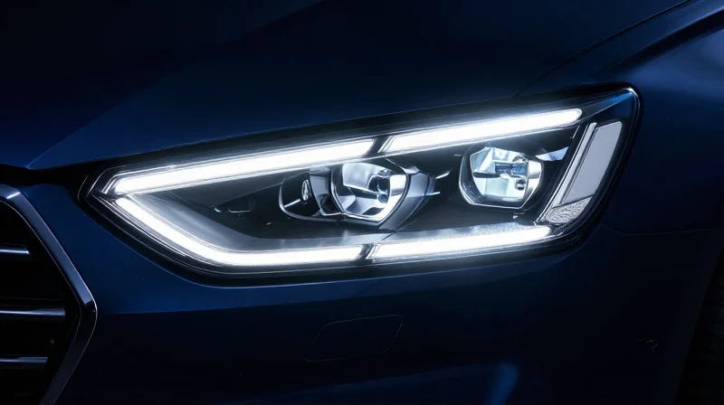
The Shift Toward High-Density Lighting
Automotive lighting has evolved from simple indicator functions to complex, high-lumen output systems, including matrix headlamps and intricate daytime running lights (DRLs). As designers pack more high-power LEDs into increasingly compact, stylized assemblies, power density has surged. Traditional FR-4 circuit boards, with their inherently poor thermal conductivity, are no longer sufficient to manage the concentrated heat loads that lead to component degradation and color shifting.
Limitations of Legacy Thermal Solutions
Legacy solutions often relied on secondary heat sinks or thermal vias to compensate for poor substrate performance. These workarounds increase mechanical complexity and physical mass, directly contradicting the automotive industry's push for lightweighting and modular, low-profile designs. Furthermore, these designs often fail to maintain the junction temperatures necessary for long-term LED reliability.
| Feature | Traditional FR-4/Vias | Aluminum Core PCB (MCPCB) |
|---|---|---|
| Thermal Conductivity | Low (approx. 0.25 W/mK) | High (1.0 - 3.0+ W/mK) |
| Weight/Profile | Heavier (requires heat sinks) | Lightweight (integral cooling) |
| Design Complexity | High (requires cooling hardware) | Low (simplified integration) |
- Why is thermal management critical for automotive LEDs?
Excessive junction temperature directly causes rapid lumen depreciation, unpredictable color shifts, and potential catastrophic failure, drastically reducing the lifespan of expensive LED modules. - What makes Aluminum Core PCBs superior in this context?
They serve a dual purpose as the circuit carrier and the primary heat spreader, allowing for rapid thermal conduction away from the LED junction directly to the chassis or external housing.
Anatomy of an Efficient MCPCB
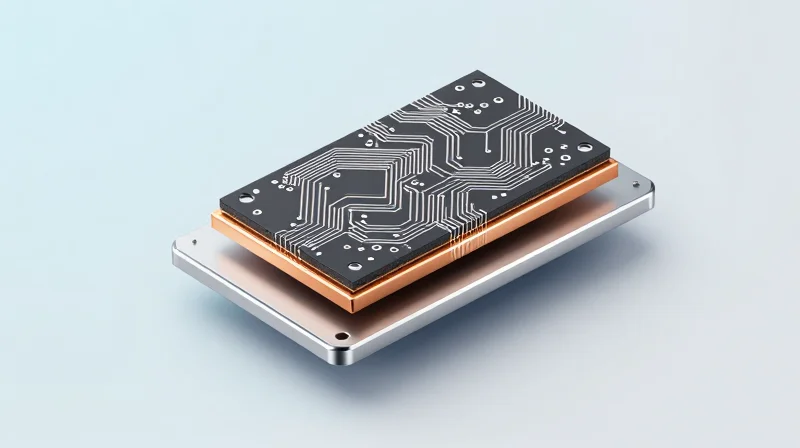
The Tri-Layer Architecture: Decoupling Thermal and Electrical Paths
The superiority of Metal Core Printed Circuit Boards (MCPCBs) in automotive lighting stems from their fundamental departure from the monolithic structure of standard FR-4 boards. While FR-4 utilizes a singular glass-reinforced epoxy substrate, an MCPCB employs a deliberate, three-layer strategy designed to minimize thermal impedance while maintaining electrical isolation.
| Layer | Material Composition | Primary Function |
|---|---|---|
| Circuit Layer | Copper Foil | Electrical signal and power distribution |
| Dielectric Layer | Thermally Conductive Polymer | Electrical insulation with low thermal resistance |
| Base Layer | Aluminum or Copper Alloy | Mechanical support and rapid heat dissipation |
Why MCPCB Outperforms FR-4
The core limitation of FR-4 is its thermal conductivity, which typically falls between 0.25 and 0.3 W/mK. In high-density automotive LED arrays, this acts as a thermal bottleneck, forcing the use of bulky heat sinks or potentially leading to premature diode failure. MCPCBs replace the core with a metal base, achieving thermal conductivities ranging from 1.0 to over 8.0 W/mK for the dielectric layer alone, with the metal base providing near-infinite heat spreading capacity.
Common Questions regarding MCPCB Material Selection
- Does the choice of aluminum versus copper base significantly affect ROI?
Aluminum is the industry standard due to its excellent balance of cost, weight, and thermal conductivity. Copper cores provide superior thermal performance but are heavier and more expensive, typically reserved for high-intensity localized heat zones. - What is the critical role of the dielectric layer?
The dielectric is the 'silent hero' of the stack-up; it must provide robust electrical isolation (breakdown voltage) while offering the lowest possible thermal resistance to pass heat from the copper foil to the metal core. - Can standard SMT assembly processes be used for MCPCBs?
Yes, although the thermal mass of the aluminum base requires adjustment to reflow soldering profiles to ensure consistent solder joint formation compared to standard FR-4 panels.
Quantifying LED Lifespan and Thermal Stability

The Thermal-Lifespan Correlation
The operational lifespan of an automotive LED is inversely proportional to its junction temperature (Tj). As temperature rises, the rate of non-radiative recombination increases, leading to lattice degradation and permanent lumen depreciation. By leveraging the high thermal conductivity of aluminum core PCBs (MCPCBs), engineers can lower the operating Tj by as much as 20°C to 30°C compared to conventional FR-4 designs, effectively doubling the Mean Time Between Failures (MTBF) under standardized automotive duty cycles.
Quantifying Thermal Impacts on Longevity
| Junction Temp (Tj) | Relative Lifespan (L70) | Failure Risk |
|---|---|---|
| 65°C | 100,000+ hrs | Negligible |
| 85°C | 60,000 hrs | Low |
| 105°C | 30,000 hrs | Moderate |
| 125°C | 10,000 hrs | High |
Thermal Stability and Material Performance
Thermal stability in automotive applications requires more than just heat dissipation; it necessitates a low coefficient of thermal expansion (CTE) mismatch between the LED die, the solder interface, and the substrate. MCPCBs provide a rigid, conductive foundation that minimizes mechanical stress during rapid thermal cycling—a frequent occurrence in automotive headlamp startup and shutdown phases.
- How does MCPCB design influence lumen maintenance?
Lowering the junction temperature prevents the degradation of the LED encapsulant and phosphor layer, ensuring that the light output remains above the 70% (L70) threshold for a significantly longer duration. - What is the role of the dielectric layer?
The dielectric layer must possess high thermal conductivity while maintaining electrical isolation; breakthroughs in filled epoxy resins now allow for lower thermal resistance, further bridging the gap between the heat source and the aluminum core. - Does thermal efficiency equate to better ROI?
Yes, by extending the LED lifecycle, manufacturers avoid costly warranty claims and vehicle recalls, directly enhancing the return on investment over the lifecycle of the lighting assembly.
Engineering Weight Reduction for Fuel Efficiency
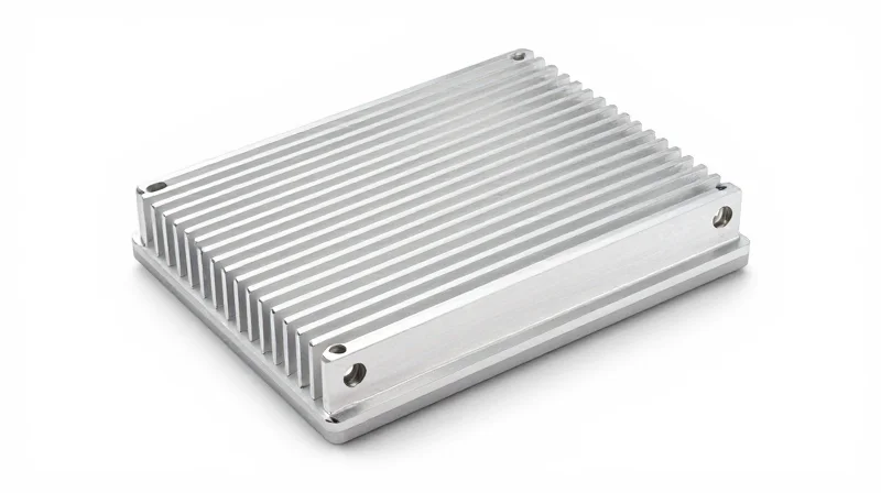
The Intersection of Thermal Management and Vehicle Mass
The transition to Aluminum Core PCBs (MCPCBs) in automotive LED applications is a critical strategy for vehicle light-weighting. By facilitating more efficient heat transfer away from high-power LED junctions, MCPCBs reduce the dependency on massive, heavy aluminum or copper heat sinks. This shift allows automotive designers to downsize secondary thermal components, contributing to lower overall vehicle mass, which directly translates to improved fuel efficiency and extended electric vehicle range.
Thermal Dissipation Comparison
| Component Strategy | Heat Dissipation Efficiency | Weight Impact |
|---|---|---|
| Standard FR-4 PCB | Low (Requires massive sink) | Heavy |
| Standard Aluminum Core | High (Reduces sink size) | Moderate |
| Advanced MCPCB + Optimized Sink | Superior (Minimal sink) | Lightweight |
Frequently Asked Questions
- How does PCB thermal performance directly reduce vehicle weight?
Higher conductivity substrates allow LEDs to reach thermal equilibrium faster. This efficiency enables engineers to design smaller aluminum heat sinks or even eliminate them by utilizing the vehicle frame as a primary heat dissipation surface. - Does switching to an aluminum base compromise electrical insulation?
No. Modern MCPCBs use a high-thermal-conductivity dielectric layer between the metal core and the copper circuitry, ensuring excellent dielectric strength while maintaining a low thermal resistance path. - Is the weight reduction significant enough to impact fuel economy?
While a single lamp assembly provides modest savings, the cumulative weight reduction from replacing bulky heatsinks across all exterior and interior LED modules is measurable, aiding compliance with increasingly stringent fuel economy and emissions standards.
Financial Impact: Reducing Warranty Costs
The Cost of Thermal Failure in Automotive Lighting
Warranty claims related to LED failures are primarily driven by thermal degradation of components and solder joint fatigue. By implementing Advanced Aluminum Core PCBs (MCPCBs), manufacturers transition from reactive cost-covering to proactive reliability, significantly lowering the Total Cost of Ownership (TCO) and mitigating high-frequency field failures.
| Failure Driver | FR-4 Substrate Impact | Aluminum Core PCB Impact |
|---|---|---|
| Junction Temperature | Rapid accumulation (High) | Efficient dissipation (Controlled) |
| Solder Joint Fatigue | High thermal stress cycles | Low stress due to CTE matching |
| Field Warranty Cost | Significant per unit | Marginal per unit |
Strategic Financial Advantages
The fiscal impact of switching to high-thermal-conductivity metal substrates extends beyond immediate component costs. By extending the Mean Time Between Failures (MTBF), original equipment manufacturers (OEMs) reduce logistics overhead, replacement inventory, and the negative brand perception associated with recall events.
- How does lower junction temperature equate to saved revenue?
Lower operating temperatures reduce the degradation rate of the LED phosphor layer, effectively doubling the operational lifespan and eliminating premature failure claims within the warranty window. - Can MCPCBs offset their higher initial material cost?
Yes, by enabling smaller secondary heat sinks and reducing the frequency of warranty-related claims, the long-term ROI significantly outweighs the premium paid for high-performance dielectric materials. - What is the primary driver of warranty reduction?
The primary driver is the improved Coefficient of Thermal Expansion (CTE) matching, which prevents mechanical stress at the solder interface—the most common point of electrical failure in automotive lighting.
Material Selection Criteria for Automotive OEMs
Choosing the correct substrate is the foundational step in ensuring the longevity and performance of automotive lighting. For high-power LED applications, OEMs must move beyond basic PCB standards to evaluate materials based on heat density, mechanical stress, and assembly throughput. The goal is to select a dielectric and base metal combination that optimizes heat transfer away from the junction while remaining cost-effective for high-volume production.
Comparative Analysis: Aluminum vs. Copper Core PCBs
| Feature | Aluminum Base (MCPCB) | Copper Base (MCPCB) |
|---|---|---|
| Thermal Conductivity | Moderate (High efficiency/cost ratio) | Superior (For extreme power density) |
| Cost Efficiency | High (Ideal for mass market) | Lower (Premium material pricing) |
| Mechanical Weight | Low (Supports light-weighting) | High (Increases assembly mass) |
| Typical Application | Headlamps, DRLs, Signal lighting | High-flux laser diodes, LIDAR modules |
Key Selection Criteria for Automotive OEMs
- Dielectric Breakdown Voltage
Automotive environments demand high dielectric strength to prevent insulation failure. Specify dielectrics with a minimum of 3kV-4kV breakdown ratings to handle transient electrical noise. - Thermal Interface Material (TIM) Compatibility
The substrate must exhibit excellent adhesion with chosen TIMs. Poor surface finish or non-planar boards result in air pockets, negating the thermal benefits of high-conductivity aluminum cores. - CTE (Coefficient of Thermal Expansion) Matching
To prevent solder joint cracking during thermal cycling (a common failure mode in under-hood lighting), the CTE of the base metal must be closely matched to the dielectric and surface-mounted components. - Manufacturing Throughput
Aluminum offers superior machinability compared to copper, allowing for complex board routing and faster drilling, which directly lowers the total cost of ownership in large-scale production.
Conclusion on Material Selection
For the vast majority of automotive lighting applications, aluminum core PCBs provide the best balance of thermal dissipation and ROI. Copper should be reserved only for applications with extreme heat flux requirements where the higher material and weight costs can be justified by specific reliability milestones or space constraints that preclude larger heat sinks.
Overcoming Integration Challenges
Optimizing Workflows for MCPCB Integration
The primary barrier to integrating Aluminum Core PCBs (MCPCBs) is the discrepancy between standard FR-4 assembly processes and the mechanical requirements of metal-core substrates. To maintain high manufacturing throughput, OEMs must transition from treating MCPCBs as specialized components to standardizing them within the initial design-for-manufacturing (DFM) phase. This shift minimizes the need for costly rework and ensures that pick-and-place precision is maintained despite differences in thermal expansion coefficients.
Comparative Analysis: Integration Methods
| Integration Strategy | Manufacturing Impact | ROI Potential |
|---|---|---|
| Standard SMT Flow | Minimal delay; requires profile tuning | High: Leverages existing infrastructure |
| Hybrid Substrate Design | Increased complexity in drill/rout | Medium: Optimized for mixed-signal zones |
| Specialized Metal-Core Mounting | High tooling requirement | Low: High setup costs but peak reliability |
Frequently Asked Questions on Implementation
- How do I mitigate thermal expansion risks during reflow?
Utilize advanced, high-Tg dielectric layers designed for MCPCBs to manage the mismatched expansion between the aluminum base and the copper circuitry, preventing fatigue in solder joints. - Does switching to aluminum substrates force a change in component selection?
Generally no, but designers must ensure that adhesive bonding materials used for non-SMT components are compatible with the operating temperature range defined by the aluminum core. - Can I maintain the same assembly speed as standard PCBs?
Yes, provided the oven profiles are adjusted for the higher thermal mass of aluminum. Failure to recalibrate profiles is the most common cause of assembly delays.
Future Trends in Automotive Lighting Thermal Tech

The Evolution of Dielectric Materials
As automotive lighting designs push toward smaller form factors and higher luminous flux, traditional dielectric layers in Aluminum Core PCBs are becoming the primary thermal bottleneck. Emerging nano-ceramic filled resins are currently redefining industry standards by offering thermal conductivities that exceed 5-8 W/mK, compared to the industry standard of 1-3 W/mK. This transition to advanced interfaces allows designers to shrink substrate footprints while maintaining safe junction temperatures, effectively maximizing both ROI and board-level efficiency.
Comparative Analysis of Thermal Substrate Trends
| Material Technology | Thermal Conductivity | Primary Benefit | Market Adoption |
|---|---|---|---|
| Standard Epoxy/FR-4 | 1-2 W/mK | Low cost | Legacy systems |
| Nano-Ceramic Filled | 5-8 W/mK | High power density | Emerging/Growth |
| Metal-Matrix Composites | 10+ W/mK | Ultimate heat flux | Experimental/Prototyping |
Key Questions Regarding Thermal Future-Proofing
- How will higher thermal conductivity impact LED ROI?
By allowing for higher drive currents without increasing the heatsink size, OEMs can utilize fewer LEDs to achieve the same brightness, significantly reducing BOM costs and assembly complexity. - Are there challenges with adopting high-k dielectric materials?
Yes, high-k materials can sometimes introduce mechanical stresses during thermal cycling. Qualification programs must focus on the coefficient of thermal expansion (CTE) matching to ensure long-term reliability in harsh automotive environments. - Is integration of these advanced materials feasible today?
Most advanced substrates are designed to be backwards compatible with standard SMT assembly processes, ensuring that manufacturers can adopt higher-efficiency materials without requiring wholesale changes to their existing production lines.
By prioritizing thermal conductivity through advanced MCPCB integration, automotive OEMs can achieve a rare synergy: higher performance for the driver and significant cost reduction for the manufacturer. Contact our engineering team today to review your current thermal stack-up and identify opportunities for your next generation of lighting designs.
