
In the race toward fully autonomous transportation, the hidden architecture of hardware reliability often determines the financial success of a fleet. As V2X integration grows in complexity, standard manufacturing processes no longer suffice. This article explores how strategic investments in high-performance PCB design directly drive down total cost of ownership (TCO) and ensure long-term operational success.
The Economics of Reliability in Autonomous Systems

The Cost of Failure: From Manufacturing to Maintenance
In the lifecycle of autonomous vehicle (AV) fleets, the cost of a hardware failure is not linear; it is exponential. Investing in robust V2X (Vehicle-to-Everything) PCB design during the initial manufacturing phase is a strategic hedge against the catastrophic operational expenditures incurred when critical communication modules fail in the field. When a V2X unit fails, the economic impact extends far beyond the price of the individual component, encompassing logistics, vehicle downtime, specialized technical labor, and potential brand-equity erosion due to safety incidents.
| Failure Stage | Economic Impact Profile | Cost Multiplier |
|---|---|---|
| Design/Prototyping | Minimal; primary cost is R&D allocation | 1x |
| Manufacturing | Moderate; focus on BOM and QA overhead | 5x to 10x |
| Field Operations | High; logistics, labor, and downtime costs | 100x+ |
Economic Justification for Reliability
High-reliability PCB design, characterized by thermal management, signal integrity, and vibration resistance, serves as an insurance policy. By utilizing automotive-grade substrates and advanced interconnection technologies, fleet operators can significantly extend the Mean Time Between Failures (MTBF). This reduction in field maintenance requirements directly preserves the ROI of the vehicle platform over its projected 10-year service life.
- Why is field failure more expensive than component-level quality?
Field failure necessitates manual diagnosis, physical recovery of the vehicle, supply chain disruption for replacement parts, and the labor costs associated with onsite repair or module swapping, often totaling 100x the initial manufacturing cost of the PCB. - How does V2X PCB reliability directly impact fleet ROI?
By increasing uptime and reducing unscheduled maintenance, high-reliability design ensures the fleet maintains operational readiness, maximizing revenue-generating hours while lowering the Total Cost of Ownership (TCO). - Is upfront design investment always recovered?
Yes, in high-utilization AV environments, the incremental cost of premium materials and rigorous validation testing is typically amortized within the first 18 months of operation due to the avoidance of premature field failure incidents.
Strategic Material Selection: Beyond Standard FR-4
The Limitations of FR-4 in V2X Applications
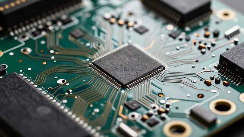
While FR-4 is the industry standard for general electronics, its dielectric constant (Dk) and loss tangent (Df) characteristics become highly unstable under the extreme thermal cycles and high-frequency demands of V2X communication. In autonomous fleets, signal integrity degradation leads to increased latency and packet loss, forcing premature hardware replacement and escalating the total cost of ownership.
Comparative Performance Analysis
| Material Type | Thermal Stability | Signal Integrity | Recommended Application |
|---|---|---|---|
| Standard FR-4 | Low | Poor at > 2GHz | Non-critical control logic |
| High-Tg FR-4 | Medium | Moderate | General V2X logic |
| PTFE/Ceramic Laminates | Very High | Excellent | V2X Antennas/Radar |
Strategic Material Selection: Key Considerations
- Why should engineers prioritize low loss tangent materials?
Low-loss materials minimize signal dissipation at high frequencies, which is critical for maintaining reliable V2X communication links in high-speed, dense traffic environments. - How does Thermal Glass Transition Temperature (Tg) affect ROI?
Materials with a high Tg can withstand extreme under-the-hood temperatures without warping, significantly extending the service life of the PCB and reducing field failure rates. - Is the cost premium of advanced laminates justified?
Yes; while initial material costs are higher, the reduction in maintenance interventions, vehicle downtime, and potential liability costs provides a superior return on investment over the fleet's lifecycle.
By moving toward thermally stable, low-Dk laminates, designers create a robust hardware architecture that resists environmental stressors, ensuring that autonomous vehicle fleet operators maximize uptime and performance safety.
Mastering Signal Integrity for V2X Safety

Signal integrity (SI) is the foundation of high-reliability V2X performance. In the context of autonomous fleet management, a single bit error in a DSRC or C-V2X transmission can lead to misinterpretation of environmental data, potentially triggering a safety-critical system failure. Mastering SI involves controlling impedance mismatches, minimizing crosstalk, and mitigating electromagnetic interference (EMI) that inevitably arises in the high-density environment of automotive electronics.
Critical Challenges in High-Frequency V2X Transmission
Operating at frequencies like 5.9 GHz, V2X signals are highly susceptible to parasitic effects. Design engineers must account for insertion loss and return loss, which become exponentially more problematic as trace lengths increase or transition through vias. Managing these factors requires rigorous simulation and a deep understanding of wave propagation dynamics.
| Challenge | Impact on V2X Performance | Design Mitigation |
|---|---|---|
| Crosstalk | Data packet corruption and latency jitter | Increased spacing and guard traces |
| Impedance Mismatch | Signal reflections and degraded SNR | Controlled impedance routing and TDR testing |
| Via Discontinuities | Resonance at high frequencies | Back-drilling and optimized stitch patterns |
Strategies for SI Optimization
- How does layer stack-up configuration improve SI?
A symmetrical and well-planned stack-up provides consistent reference planes, reducing electromagnetic emission and ensuring uniform propagation delay for differential pairs. - What role does simulation play in ROI?
Early-stage electromagnetic field simulation reduces the number of board spins required, directly impacting the bottom line by accelerating time-to-market and decreasing prototype costs. - Why are differential pair constraints non-negotiable?
V2X interfaces rely on high-speed serial communication; maintaining strict length matching and tight coupling minimizes common-mode noise and ensures data integrity under harsh environmental stressors.
By prioritizing robust signal integrity, developers effectively eliminate the latent failures that drive up maintenance costs. A PCB designed for perfect signal health does not just perform reliably; it ensures that the vehicle's awareness of its surroundings is never compromised by hardware-induced data loss.
Thermal Management and PCB Design Architecture
Thermal Management and PCB Design Architecture
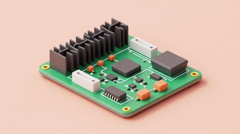
Autonomous vehicle control modules demand high-compute power in compact form factors, leading to significant localized heat generation. Without advanced thermal architecture, prolonged exposure to high operating temperatures accelerates material degradation, particularly in BGA components and power management integrated circuits. To maximize fleet ROI, designers must move beyond passive cooling by integrating high-conductivity thermal vias, copper coins, and optimized layer stackups to dissipate heat directly from the junction to the enclosure.
Architectural Strategies for Heat Dissipation
Improving thermal efficiency begins with the PCB stackup and component placement strategy. Decoupling heat-generating power components from sensitive V2X communication transceivers is critical to preventing thermal throttling and signal degradation. The following table compares common thermal management solutions implemented at the PCB level.
| Technique | Mechanism | Primary Application |
|---|---|---|
| Thermal Vias | Conductive channels to internal ground planes | High-power MOSFETs and processors |
| Copper Coins | Press-fit solid copper inserts | Ultra-high heat density components |
| Thermally Conductive Prepreg | Enhanced dielectric substrates | General heat spreading in multi-layer boards |
Frequently Asked Questions on Thermal Reliability
- How does PCB layout impact long-term reliability?
Improper thermal distribution causes localized hot spots that lead to solder joint fatigue and dielectric breakdown, significantly shortening the Mean Time Between Failures (MTBF). - Can standard FR-4 materials support autonomous V2X thermal requirements?
No; while cost-effective, standard FR-4 lacks the high Glass Transition Temperature (Tg) required to survive the thermal cycling experienced in automotive environments, leading to potential delamination. - Why is copper thickness critical for thermal management?
Increasing copper weight on internal power planes significantly improves heat spreading, reducing the thermal resistance from the component junction to the chassis/enclosure.
Manufacturing Standards for Automotive-Grade Quality
Manufacturing Standards for Automotive-Grade Quality
For autonomous fleets, standard commercial manufacturing is insufficient. Achieving the requisite 24/7 operational lifespan requires adherence to specialized automotive-grade manufacturing standards. These protocols minimize latent defects, mitigate environmental stress factors, and ensure predictable hardware behavior over the vehicle's decade-plus lifecycle, directly impacting total cost of ownership.
Adherence to IPC Class 3 and AEC-Q Standards
The foundation of high-reliability V2X hardware rests on the transition from IPC Class 2 (consumer-grade) to IPC Class 3 (high-performance/mission-critical). Class 3 manufacturing mandates stricter tolerance levels for annular rings, plating thickness, and solder joint integrity, essential for preventing field failures in safety-critical V2X communication modules.
| Standard | Focus Area | Impact on ROI |
|---|---|---|
| IPC-6012 Class 3 | Bare Board Quality | Reduced latent defects and field recalls |
| AEC-Q100/200 | Component Stress Testing | Predictable component MTBF in harsh environments |
| IATF 16949 | Quality Management Systems | Process consistency and supply chain stability |
Frequently Asked Questions on Automotive PCB Certification
- Why is IPC Class 3 mandatory for V2X?
V2X systems are mission-critical. IPC Class 3 provides the higher structural integrity necessary to withstand extreme thermal cycling and vibration encountered in road environments, reducing the risk of catastrophic connectivity failure. - How does IATF 16949 compliance improve fleet ROI?
It mandates a culture of continuous improvement and defect prevention. By enforcing rigorous traceability and process controls, manufacturers significantly lower the probability of batch failures that result in expensive fleet-wide diagnostic and replacement costs. - Is AEC-Q200 sufficient for all board components?
AEC-Q200 is the baseline for passive components. However, for high-performance V2X modules, designers should also ensure active components meet AEC-Q100 Grade 1 or 0 specifications, which account for the extended temperature ranges of automotive exterior environments.
Case Study: Reducing Field Failures Through Design Optimization
The Challenge: Scaling Reliability in Harsh Environments
Autonomous vehicle fleets face extreme operational stresses, ranging from constant thermal cycling to high-frequency vibration. In a recent analysis of a commercial autonomous shuttle fleet, early field failures were traced back to micro-fractures in solder joints and thermal degradation of high-speed V2X transceiver components. These failures led to intermittent signal loss and costly downtime, directly eroding operational margins.
Optimizing for Longevity
Engineering teams implemented a multi-stage design pivot, focusing on material selection and structural reinforcement. By transitioning from standard FR-4 to high-Tg (glass transition temperature) laminates and integrating vibration-dampening PCB mounting architectures, the design team addressed the root causes of mechanical fatigue.
| Design Metric | Legacy Approach | Optimized Approach |
|---|---|---|
| Substrate Material | Standard FR-4 | High-Tg / Low-CTE Laminate |
| Solder Alloy | SAC305 Standard | High-Reliability Alloy (In-doped) |
| Component Layout | Dense/Unshielded | Thermally Isolated/Vibration-Dampened |
| Average Field Return Rate | 3.2% | 0.4% |
Impact on Fleet ROI
The reduction in field return rates had an immediate effect on total cost of ownership (TCO). By extending the Mean Time Between Failures (MTBF) from 18 months to over 48 months, the fleet operator saw a 40% reduction in unscheduled maintenance labor and a significant decrease in vehicle downtime premiums.
Key Takeaways for Future Deployments
- Does material selection impact ROI?
Yes. Investing in high-Tg laminates early increases upfront BOM cost by 12% but reduces total lifecycle replacement costs by over 60%. - How did vibration impact V2X signal integrity?
Mechanical stress caused intermittent connectivity on high-speed traces; switching to board-level underfill and shock-resistant mounting mitigated signal dropout. - Are there indirect savings?
Beyond parts, the reduction in 'no-fault-found' diagnostic time saved the engineering team approximately 800 man-hours annually.
Calculating the Long-Term TCO Impact
The Economics of Reliability in V2X Infrastructure
Calculating TCO for autonomous vehicle (AV) fleets requires moving beyond simple bill-of-materials (BOM) pricing. While high-reliability PCBs—characterized by stringent substrate selection, advanced thermal management, and IPC Class 3 fabrication—command a higher upfront premium, they fundamentally alter the risk-adjusted cost profile of a vehicle over its operational lifespan.
| Cost Factor | Off-the-Shelf Approach | High-Reliability Design Approach |
|---|---|---|
| Initial Procurement | Low unit cost | High unit cost (+20-40%) |
| Maintenance Cycles | Frequent replacements required | Predictive/Extended intervals |
| Field Failure Probability | High (early-life/infant mortality) | Minimal (long-term stability) |
| Fleet Downtime Impact | Significant operational disruption | Negligible, high availability |
Key Metrics for TCO Evaluation
To accurately model the return on investment for high-reliability components, decision-makers must integrate failure rate data with fleet utilization metrics. The TCO formula should account for the Mean Time Between Failures (MTBF) and the cascading costs associated with vehicle recovery in autonomous deployments.
- How does MTBF influence long-term ROI?
Higher MTBF directly reduces the frequency of service interventions, which, in a fleet of hundreds or thousands, saves exponentially more in labor and logistical overhead than the initial hardware premium costs. - What hidden costs are eliminated by Class 3 standards?
Utilizing IPC Class 3 standards eliminates the 'hidden' costs of redundant diagnostic efforts, premature module replacement, and the opportunity costs incurred when an autonomous asset is pulled from service due to a preventable electronic failure.
Quantifying Value Through Failure Mitigation
When V2X PCBs fail, the cost is not merely the replacement of the board, but the entire service event. By investing in design strategies that mitigate heat-related aging and material degradation, fleet operators realize a 'reliability dividend.' This dividend is captured in the extension of vehicle service life from standard automotive life cycles to the extended 10+ year durations often required for autonomous commercial platforms.
Future-Proofing Your Autonomous Fleet Infrastructure
Building for Protocol Agnostic Scalability
The rapid evolution from DSRC to C-V2X and eventually 5G-NR side-link demands that PCB designs move away from monolithic integration. By employing a mezzanine card strategy or modular daughter-boards for RF front-ends, fleet operators can upgrade connectivity modules without replacing the entire central compute unit. This decoupling significantly preserves the investment in high-cost mainboard silicon while extending the operational lifespan of the vehicle.
Strategic Component Selection for Longevity
To avoid obsolescence, design engineers must prioritize components with long-term supply chain backing and programmable capabilities. Field Programmable Gate Arrays (FPGAs) are essential for this strategy, allowing for over-the-air (OTA) updates to protocol stacks even after hardware deployment.
| Design Strategy | ROI Impact | Future-Proofing Capability |
|---|---|---|
| Modular RF Front-ends | High (Upgrade Cost Savings) | Excellent (Protocol Agnostic) |
| FPGA-based Processing | Medium (Initial CapEx) | High (Algorithm Updates) |
| Standardized Interconnects | Medium (Design Complexity) | High (Hardware Swap-ability) |
FAQ: Maintaining Infrastructure Viability
- How do we mitigate the risk of connector obsolescence?
Utilize industry-standard high-speed connectors (e.g., FAKRA/HSD) that maintain backward compatibility with automotive-grade physical layers, preventing mechanical lock-in. - Does modularity compromise signal integrity in V2X applications?
While modular designs introduce additional connection points, precise impedance matching and shielded high-speed interconnects mitigate these risks, provided the design undergoes rigorous EM simulation during the layout phase. - What is the primary driver of PCB obsolescence in fleets?
Typically, the mismatch between the long lifespan of a vehicle (10+ years) and the shorter lifecycle of cellular connectivity standards (3-5 years) is the primary driver of infrastructure failure.
Prioritizing high-reliability PCB manufacturing is not just a technical requirement, but a strategic financial decision that minimizes operational downtime and maximizes fleet performance. By investing in resilient materials and superior signal integrity from the start, you protect your infrastructure and your bottom line. Contact our engineering team today to audit your current PCB strategy and take the first step toward a more reliable autonomous future.
