
In the fast-paced world of medical instrumentation, a single point of failure is more than a technical error—it is a patient safety risk. As patient monitoring hardware trends toward smaller, more connected, and high-density designs, the margin for error shrinks. This guide explores the critical intersection of Design for Manufacturing (DFM) and reliability, providing engineering teams with a blueprint for building mission-critical electronics that stand the test of time.
The High Stakes of Medical PCB Reliability
Unlike consumer electronics, where a device failure results in a minor inconvenience, failure in a patient monitor PCB can lead to catastrophic medical outcomes. The circuitry must maintain absolute signal integrity, consistent thermal management, and fail-safe operation under diverse clinical conditions. Designing for medical high-reliability requires a fundamental shift from 'time-to-market' optimization to 'fail-safe' optimization, ensuring that every trace, component, and solder joint meets stringent ISO 13485 and IEC 60601 standards.
Differentiating Medical vs. Consumer Electronics
| Feature | Consumer Electronics | Medical Patient Monitors |
|---|---|---|
| Failure Consequence | Inconvenience/Warranty claim | Life-critical danger |
| Regulatory Oversight | General CE/FCC | FDA/IEC 60601-1 Class II/III |
| Operating Environment | Controlled/Office | Unpredictable/Clinical/Electromagnetic interference |
| Component Quality | Commercial grade | Industrial/Automotive/Medical grade |
Critical Reliability Challenges
The primary threat to medical PCB reliability is intermittent failure caused by environmental stress or manufacturing inconsistencies. Because patient monitors are used in high-acuity settings, they are subject to constant electromagnetic interference (EMI), fluid exposure, and potential physical impact. Designers must account for creepage and clearance distances to ensure electrical isolation, preventing leakage currents that could harm a patient connected to the device.
- Why is thermal management critical in patient monitoring?
Thermal fatigue induces micro-cracks in solder joints over time. Effective heat dissipation preserves component longevity and prevents drift in precision sensing circuits. - How does EMI shielding impact reliability?
Medical environments are electrically noisy. Proper board-level shielding and differential signal routing are essential to prevent false alarms or corrupted vital sign data. - What role does trace geometry play in high-reliability?
Inadequate trace widths or poor annular ring design can lead to PCB delamination during thermal cycling, causing intermittent data loss that is notoriously difficult to diagnose.
Mastering High-Density Interconnect (HDI) Routing
Core Principles of HDI for Medical Electronics
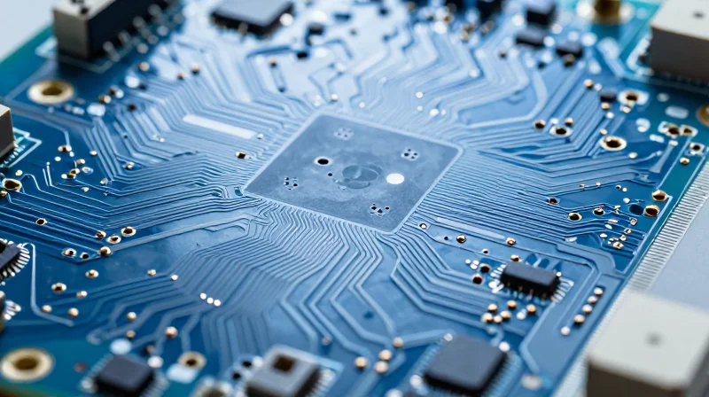
HDI routing allows for increased component density and signal integrity in miniaturized medical devices, yet it requires precise execution to avoid reliability failure. By utilizing microvias, blind vias, and buried vias, designers can reduce layer counts while optimizing the signal path for sensitive physiological monitoring circuits.
Comparison of Via Technologies in HDI
| Via Type | Primary Advantage | Manufacturing Impact |
|---|---|---|
| Microvia | High density routing | Higher fabrication costs |
| Blind Via | Saves space on surface | Requires sequential lamination |
| Buried Via | Internal connectivity | Increased cycle time |
Mitigating Signal Integrity and Cross-Talk
In patient monitors, noise floor management is critical for accurate signal acquisition (ECG, EEG). Tight HDI routing patterns increase the risk of capacitive and inductive coupling. To maintain signal integrity, designers must strictly adhere to the '3W rule' for trace separation and prioritize ground plane continuity beneath critical signal traces.
Frequently Asked Questions on HDI Routing
- How do I ensure structural integrity with microvias?
Avoid stacking microvias directly over larger through-hole vias, which can lead to stress points during thermal cycling. Staggering vias provides better mechanical stability for the copper structure. - What is the primary trade-off for high-density routing?
The main trade-off is the increased thermal density. HDI designs require advanced thermal via arrays to pull heat away from active sensors and processors to prevent localized hot spots. - Is rigid-flex necessary for all HDI patient monitors?
Not necessarily, but it is highly recommended when monitors require complex form factors or dynamic movement, as it minimizes interconnect failure points compared to board-to-board connectors.
Thermal Management Strategies for Dense Assemblies
Thermal Management Strategies for Dense Assemblies
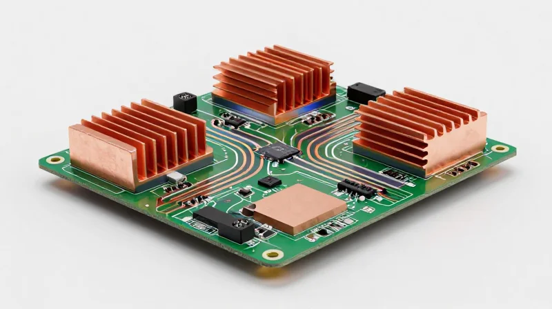
In dense medical PCB assemblies, heat dissipation is hindered by tight enclosure constraints and the frequent requirement for fanless, silent operation. Engineers must shift from active cooling to passive thermal management techniques by prioritizing low-thermal-resistance board materials, strategic component placement to avoid hotspots, and the integration of thermal vias that effectively transfer heat from power-dense components into internal copper planes or dedicated heat sinks.
Passive Dissipation Techniques
| Strategy | Implementation | Benefit |
|---|---|---|
| Thermal Vias | Array of plated through-holes under IC pads | Lowers junction-to-ambient resistance |
| Copper Pour | Dedicated thick copper areas (2oz+) | Acts as a secondary heat spreader |
| Component Spacing | Isolating high-power MOSFETs/FPGAs | Prevents localized thermal accumulation |
Frequently Asked Questions
- How do thermal vias impact board reliability?
While necessary for heat transfer, thermal vias should be filled and capped (VIPPO) to prevent solder wicking and ensure structural integrity in high-density medical designs. - Can I use standard FR-4 for high-heat medical boards?
Standard FR-4 is often insufficient. High-reliability designs should specify materials with a high Glass Transition Temperature (Tg) to prevent PCB delamination and impedance instability during thermal cycling. - What is the role of the enclosure in thermal management?
The enclosure acts as the ultimate heat sink. Designs should incorporate thermal interface materials (TIM) that bridge the gap between the PCB's ground plane or heat-producing components and the device's chassis.
Prioritizing Signal Integrity in Sensitive Monitoring Equipment

Patient monitors must detect microvolt-level biosignals like ECG and EEG, which are inherently susceptible to ambient electromagnetic noise. In high-density medical PCB designs, signal integrity (SI) is not merely a performance goal but a clinical safety requirement. Failure to mitigate electromagnetic interference (EMI) and radio-frequency interference (RFI) leads to artifact-heavy readings, diagnostic inaccuracies, and potential alarm fatigue.
Strategies for EMI/RFI Mitigation
The primary objective is to minimize loop area and maintain constant impedance across high-speed digital and sensitive analog partitions. Implementing these strategies early in the design phase significantly reduces the need for expensive post-certification shielding.
| Strategy | Implementation Focus | Clinical Benefit |
|---|---|---|
| Layer Stackup | Dedicated analog ground planes | Reduced crosstalk and noise floor |
| Differential Pairs | Strict length matching and coupling | Improved Common Mode Rejection |
| Component Placement | Isolate high-speed clocks from AFEs | Prevention of switching noise injection |
Frequently Asked Questions Regarding Signal Integrity
- How does digital switching noise affect analog sensitivity?
Rapid transients from digital clocks and high-speed data buses create return currents that can modulate sensitive analog ground references, manifesting as baseline wander or jitter in biosignals. - Is via stitching necessary for high-frequency isolation?
Yes; via stitching creates a low-impedance path to ground and prevents resonance in cavities between planes, which is crucial for meeting stringent IEC 60601-1-2 EMC standards. - What is the role of guard traces in medical PCBs?
Guard traces act as an electrostatic shield around sensitive signal nodes, minimizing leakage currents and suppressing surface-level crosstalk in high-impedance input circuits.
Designers should prioritize the use of buried vias and constrained routing keep-outs to ensure that digital high-speed return paths do not intersect with sensitive analog reference planes. By treating the PCB as a complex radio-frequency environment, developers ensure that physiological monitoring accuracy remains consistent under all clinical conditions.
Selecting Materials for Longevity and Bio-Compatibility
The operational reliability of medical patient monitors is inextricably linked to the chemical and physical integrity of the PCB assembly. Choosing materials that endure repetitive clinical sanitation and long-term deployment requires a deliberate selection of laminates and surface finishes.
Substrate Selection for Environmental Resilience
Standard FR-4 is often insufficient for medical-grade devices that undergo high-heat or moisture-heavy sterilization. Designers must evaluate substrates based on their Glass Transition Temperature (Tg) and Coefficient of Thermal Expansion (CTE).
| Material Type | Primary Advantage | Medical Application |
|---|---|---|
| High-Tg Polyimide | Excellent thermal stability | High-heat sterilization environments |
| Modified FR-4 | Balanced cost and performance | General patient monitoring sensors |
| PTFE/Ceramics | Low signal loss/high stability | High-frequency diagnostic modules |
Ensuring Bio-Compatibility and Chemical Resistance
Beyond electrical performance, the materials must resist degradation from common medical cleaning agents such as glutaraldehyde or isopropyl alcohol. Surface finishes like Electroless Nickel Immersion Gold (ENIG) provide a chemically stable barrier, preventing oxidation and minimizing the leaching of heavy metals into the device enclosure.
Frequently Asked Questions
- Why is CTE matching important for medical PCBs?
Matching the CTE of the substrate to the copper layers reduces mechanical stress on vias and solder joints, preventing cracks during repeated thermal cycling caused by sterilization. - Is ENIG sufficient for long-term reliability?
ENIG is excellent for bio-compatibility and preventing corrosion, but ensure the nickel layer thickness is strictly controlled to avoid brittle intermetallic compound formation. - How does moisture absorption impact monitor performance?
High moisture absorption can lead to dielectric constant shifts and potential delamination; low-loss materials are required to maintain signal integrity in humid hospital environments.
Implementing DFM Checks to Prevent Field Failures

Shifting DFM Analysis Left
Traditional PCB design flows often treat manufacturing feedback as a late-stage gate, leading to costly re-spins. For patient monitoring equipment, shifting DFM analysis to the pre-layout and routing stages is essential. By utilizing automated software rule-checkers during the design phase, engineers can identify clearance violations, acid traps, and thermal relief issues before a single Gerber file is generated.
Key DFM Constraints for Reliability
| DFM Check Item | Medical Failure Mode | Prevention Strategy |
|---|---|---|
| Solder Mask Registration | Inter-lead Bridging | Increase dams to 0.1mm minimum |
| Via-in-Pad | Voiding and Leaching | Use epoxy-filled, capped vias |
| Copper Weight | Thermal Stress Cracking | Distribute heavy traces across layers |
Automated Verification Strategies
Automated DFM tools evaluate designs against specific fabrication capabilities. For high-reliability medical devices, these tools should be configured with custom constraints that exceed standard commercial tolerance levels.
- Why should DFM checks be automated?
Automation eliminates human error in checking thousands of design rules, ensuring consistent compliance with IPC Class 3 standards required for medical electronics. - What is the primary benefit of early DFM integration?
It minimizes the risk of 'latent defects'—issues that pass initial electrical testing but lead to premature field failure after long-term exposure to hospital environments. - How does DFM prevent assembly failures?
By enforcing robust pad geometries and optimizing thermal relief, DFM ensures that components remain securely attached despite constant vibration or rapid thermal cycling.
Standardizing Rule Sets
/* Example DFM Constraint Logic for High-Rel Patient Monitors */
RULE_SET Medical_Class3 {
  MIN_ANNULAR_RING: 0.15mm;
  MIN_COPPER_TO_EDGE: 0.5mm;
  VIA_PLATING_THICKNESS: 25um;
  DRILL_TOLERANCE: 0.025mm;
}
Regulatory Compliance and Documentation Best Practices
Integrating Compliance into the Design Lifecycle
Achieving regulatory approval is not a post-design activity; it is a foundational requirement that must be embedded into the Design for Manufacturing (DFM) and Design for Reliability (DFR) processes. For high-reliability medical electronics, documentation must serve as a verifiable trail of evidence, demonstrating that every design decision—from stack-up selection to thermal management—aligns with risk mitigation requirements defined in ISO 14971.
Essential Documentation Pillars
| Requirement Category | Key Artifacts | Regulatory Focus |
|---|---|---|
| Design Integrity | Schematics, BOMs, PCB Layout Files | Traceability and Version Control |
| Risk Management | DFMEA Reports, Hazard Analysis | ISO 14971 Compliance |
| Verification | Test Plans, Signal Integrity Reports | IEC 60601 Performance Validation |
Best Practices for Audit Readiness
- How do we ensure full traceability for PCB components?
Utilize a centralized Product Lifecycle Management (PLM) system to link every BOM component to its specific datasheet, compliance certificate (RoHS/REACH), and manufacturing lot history. - What role does Design Failure Mode and Effects Analysis (DFMEA) play?
DFMEA must be an iterative document. It should explicitly record potential failure modes of the PCB layout, such as trace impedance mismatch or inadequate clearance, and document the implemented design mitigations. - How should verification documentation be structured?
Verification reports must explicitly map test results back to the original design requirements. This bidirectional traceability is critical for demonstrating compliance during FDA or CE marking audits.
Consistency is the cornerstone of regulatory success. Organizations should automate documentation generation where possible by using script-based exports from EDA tools to populate design history files (DHF). By maintaining rigorous DFM checks that log every design rule violation and the subsequent waiver or correction, teams create a defensible record of engineering diligence that drastically shortens the path to certification.
The Future of Reliable Medical Hardware Design
Leveraging Digital Twin Simulations
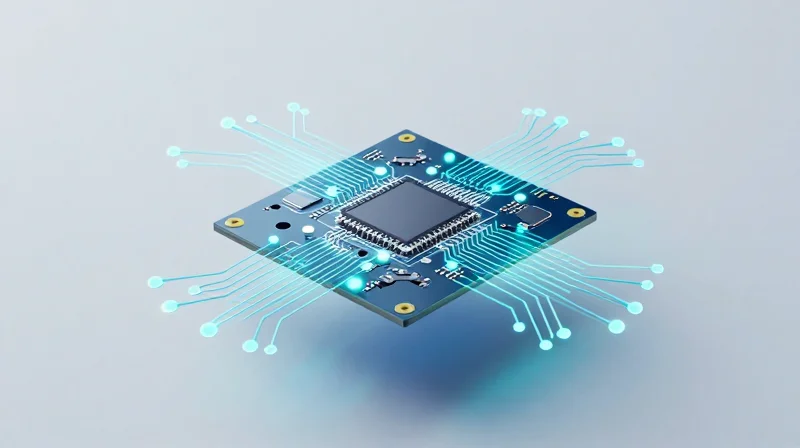
The future of high-reliability PCB design lies in shifting from physical prototyping to virtual digital twin environments. By creating high-fidelity digital replicas of patient monitors, engineers can simulate environmental stresses, thermal dissipation, and signal integrity issues long before the first physical board is manufactured. This methodology allows for the testing of extreme edge cases—such as electromagnetic interference (EMI) fluctuations in dense clinical environments—that would be prohibitively expensive or time-consuming to replicate in a laboratory setting.
Comparison of Traditional Prototyping vs. Digital Twin Validation
| Feature | Traditional Prototyping | Digital Twin Simulation |
|---|---|---|
| Validation Speed | Weeks/Months | Hours/Days |
| Cost of Failure | High (Hardware Scrap) | Low (Computing Resources) |
| Stress Testing | Limited by Physical Setup | Virtually Unlimited |
| Design Iteration | Slow and Incremental | Rapid and Automated |
Advanced Testing and Predictive Reliability
Next-generation medical electronics are moving toward 'Design for Reliability' (DfR) rather than just 'Design for Manufacturing' (DfM). This approach incorporates AI-driven predictive modeling that analyzes historical field data to identify potential failure modes in component aging and interconnect fatigue. By embedding sensor-fusion capabilities directly into the PCB architecture, patient monitors of the future will be capable of self-diagnosing degradation in real-time, effectively alerting maintenance teams before a critical component failure occurs in a live clinical setting.
Frequently Asked Questions
- How does AI integration impact DFM workflows?
AI automates the detection of complex geometric rule violations that traditional DFM software often misses, specifically optimizing layer stack-ups for thermal performance in small-form-factor medical devices. - Will digital twins replace physical compliance testing?
No, they act as a pre-compliance filter. Digital twins significantly improve first-pass yields during formal IEC 60601 certification by ensuring all potential design flaws are purged before expensive lab testing begins. - How does predictive monitoring affect component selection?
Designers must increasingly select components that provide telemetry or status signaling, allowing the PCB’s embedded system to monitor component 'health' over time.
Achieving absolute reliability in patient monitoring hardware requires a proactive approach to DFM that begins at the schematic level. By focusing on thermal dynamics, signal integrity, and manufacturing-ready layouts, your team can drastically reduce field failures and ensure patient safety. Ready to harden your medical device design process? Contact our engineering team today to review your current project and optimize for mission-critical performance.
