
The demand for high-performance, invisible hearing solutions is pushing medical electronics to their physical limits. As patients demand smarter, smaller devices, traditional assembly methods are hitting a developmental wall. This article explores how the shift to rigid-flex PCB architecture is enabling the next generation of auditory innovation.
The Changing Landscape of Audiology Electronics

The Convergence of Patient Demand and Engineering Constraints
Modern audiology patients increasingly prioritize aesthetics, driving a market-wide shift toward nearly invisible, in-the-canal (ITC) and completely-in-the-canal (CIC) devices. This demand for extreme miniaturization has rendered traditional interconnect methods—relying on bulky connectors and cumbersome wire harnesses—obsolete. To maintain signal integrity while shrinking the physical footprint, manufacturers are adopting rigid-flex PCB technology, which allows for three-dimensional folding and space-efficient component placement.
Comparative Analysis: Traditional Assembly vs. Rigid-Flex
| Feature | Traditional Assembly | Rigid-Flex PCB |
|---|---|---|
| Form Factor | High volume, rigid geometry | Ultra-compact, 3D conformable |
| Reliability | Lower (solder joint failure at connectors) | Higher (integral construction) |
| Assembly Complexity | High (labor-intensive wiring) | Low (automated production) |
| Signal Integrity | Susceptible to interference | Excellent (controlled impedance paths) |
Addressing Implementation Challenges
- Why does space-saving impact battery life?
Smaller footprints often leave limited space for battery capacity; rigid-flex boards optimize interior volume, allowing designers to maximize the battery chamber size while maintaining miniaturized circuitry. - Is rigid-flex technology more durable for daily use?
Yes. By eliminating wire connectors that are prone to oxidation and vibration-induced fatigue, rigid-flex assemblies provide a monolithic, robust structure that withstands the rigors of frequent insertion and removal. - How does this technology improve manufacturing efficiency?
Rigid-flex boards are designed as a single, foldable unit. This eliminates the need for manual point-to-point wiring, significantly reducing assembly time and human error during the production of intricate hearing devices.
Limitations of Legacy PCB Assembly Methods
The Constraints of Conventional Interconnects
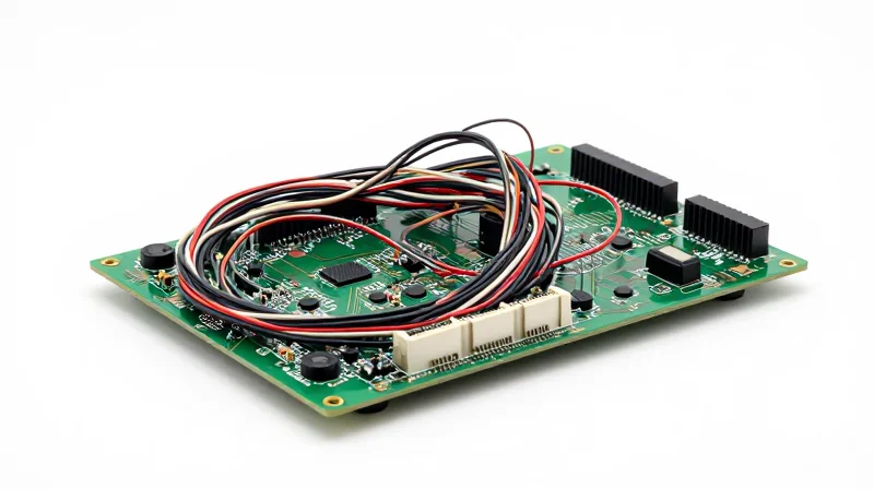
Traditional hearing aid assembly, characterized by rigid-only circuit boards interconnected via discrete wiring harnesses, creates significant barriers to next-generation miniaturization. These methods rely on manual or semi-automated soldering of individual wires to PCB pads, a process that is inherently bulky and prone to mechanical fatigue. In the confined space of a modern RIC (Receiver-in-Canal) or IIC (Invisible-in-Canal) device, the physical volume occupied by wire routing and solder joints consumes critical real estate that could otherwise be dedicated to battery capacity or advanced DSP (Digital Signal Processor) performance.
Signal Integrity and Reliability Challenges
Beyond physical dimensions, legacy assembly methods introduce electrical vulnerabilities. Discrete wires acting as point-to-point interconnects lack the controlled impedance and shielding found in integrated flexible circuitry, leading to susceptibility to EMI (Electromagnetic Interference). This becomes increasingly problematic as hearing aids evolve into connectivity hubs supporting high-bandwidth Bluetooth streaming, where cross-talk and signal degradation can compromise audio fidelity.
| Feature | Legacy Wire-Harness Method | Rigid-Flex PCB Method |
|---|---|---|
| Form Factor | High volume, rigid geometry | Low profile, adaptable geometry |
| Assembly Reliability | Prone to fatigue at solder joints | High integrity due to integrated traces |
| Signal Integrity | Poor (lack of shielding) | Excellent (controlled impedance) |
| Space Efficiency | Low (wiring takes up internal space) | High (utilizes 3D volume) |
Frequently Asked Questions Regarding Legacy Limitations
- Why do wire harnesses increase failure rates in hearing aids?
Wire harnesses introduce multiple manual termination points. Every solder joint is a potential failure point, and the inherent stiffness of wire insulation can transmit mechanical stress to the PCB, leading to pad lifting or trace fracturing during daily use. - How does legacy assembly restrict battery life?
The physical bulk of manual wiring and the inefficient use of 3D space mean designers are forced to sacrifice internal volume, limiting the size of the zinc-air or lithium-ion battery that can be integrated into the chassis. - Is EMI a significant concern with discrete wiring?
Yes. Discrete wires act as miniature antennas. In high-density electronics, unshielded wires are highly susceptible to picking up noise from external sources and internal clock signals, which can manifest as audible hiss or interference in the patient's output.
Understanding Rigid-Flex PCB Architecture
Defining Rigid-Flex Architecture
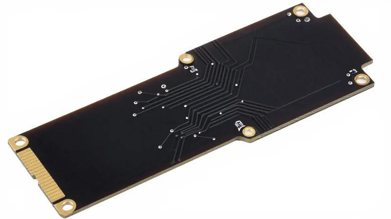
Rigid-flex circuits are hybrid assemblies composed of one or more rigid boards combined with flexible circuit substrates. In the context of hearing aids, this architecture allows the device to fold or conform to the tight anatomical constraints of an ear mold while providing dedicated, secure zones for surface-mount technology (SMT) components like processors, microphones, and batteries.
Key Structural Advantages
| Feature | Rigid-Flex PCB | Traditional Assembly |
|---|---|---|
| Interconnect Method | Integrated Plated Through-Holes | Manual Wire Harnessing |
| Reliability | High (Vibration Resistant) | Low (Solder Joint Fatigue) |
| Component Density | Very High (3D Packaging) | Low (Sequential Layouts) |
| Volume Efficiency | Optimized for Curvature | Inefficient/Bulky |
Core Benefits for Miniaturization
By replacing traditional discrete wire interconnects with flexible polyimide layers, manufacturers can realize significant space savings. These layers act as integrated ribbons that carry signal and power through tight corners within the chassis, reducing the total footprint by up to 40% compared to legacy architectures.
- How does rigid-flex improve signal integrity?
By eliminating mechanical connectors and manual solder points, rigid-flex reduces parasitic capacitance and inductance, leading to cleaner signal paths for sensitive digital signal processing. - Is rigid-flex durable enough for daily wear?
Yes, the inherent flexibility of polyimide substrates allows the board to withstand the repetitive mechanical stresses caused by inserting and removing the device from the ear canal. - Does this impact heat dissipation?
Rigid-flex allows for more efficient board layout, keeping heat-sensitive components isolated from the main heat-generating power management integrated circuits (PMICs).
Space Optimization and Miniaturization Benefits

Achieving High-Density Integration through Multi-Plane Folding
Rigid-flex circuits replace bulky, multi-board assemblies and fragile wiring looms with a singular, interconnected substrate. By leveraging flexible polyimide layers, manufacturers can fold circuitry into the complex, ergonomic curves of modern hearing aid housings. This multi-plane configuration transforms wasted void space into viable real estate, allowing for the integration of advanced DSP chips, wireless antennas, and larger batteries without increasing the physical footprint of the device.
Impact of Space-Saving Architectures
| Feature | Traditional Assembly | Rigid-Flex Technology |
|---|---|---|
| Component Density | Low (limited by flat surface) | High (3D volumetric packing) |
| Internal Wiring | Bulky wire harnesses | Integrated flexible circuits |
| Mechanical Stress | High at solder joints | Low (flexible dampening) |
| Assembly Speed | Slow manual wiring | Automated rapid assembly |
Frequently Asked Questions Regarding Miniaturization
- How does folding the PCB improve device reliability?
Folding eliminates the need for manual cable connections, which are prone to fatigue and signal loss, effectively reducing the total number of failure points inside the hearing aid. - Does rigid-flex integration limit hardware accessibility for repairs?
While designs are more compact, modern rigid-flex structures are engineered with modular fold-out sections, ensuring that core components remain accessible for diagnostics and maintenance during the product lifecycle. - Can rigid-flex PCBs accommodate wireless connectivity?
Yes, the flexible sections of the PCB can be shaped to act as optimized antennas, allowing for robust Bluetooth and NFMI performance in confined spaces where traditional internal antennas would fail.
Enhancing Signal Integrity and Reliability
Minimizing Failure Points
In traditional hearing aid assembly, inter-board connections—such as soldered ribbon cables or gold-wire connectors—serve as the primary failure points. These mechanical interfaces are susceptible to thermal expansion, vibration, and moisture ingress, which can lead to intermittent contact or complete signal loss. Rigid-flex technology eliminates these vulnerable junctions by creating a continuous, monolithic circuit path. By integrating flexible polyimide layers directly into the board substrate, the design removes the need for physical solder joints or crimped connectors, fundamentally increasing the device's mean time between failures (MTBF).
Comparative Reliability Analysis
| Failure Factor | Traditional Assembly | Rigid-Flex Technology |
|---|---|---|
| Interconnect Points | High (Multi-solder sites) | Minimal (Integrated traces) |
| Vibration Resilience | Low (Stress on cables) | High (Stress-free routing) |
| Signal Impedance | Inconsistent | Controlled and stable |
| Moisture Sensitivity | High (Corrosion risk) | Low (Encapsulated circuits) |
Signal Integrity and Electromagnetic Interference
Signal integrity in small, high-gain devices is paramount. Traditional wire harnesses often create unshielded loops that act as antennas, introducing unwanted electromagnetic interference (EMI) into the audio signal path. Rigid-flex boards allow for precise ground plane integration and controlled impedance traces across the flexible sections. This shielding effectiveness ensures that sensitive digital and analog signals remain decoupled from internal noise sources, resulting in a cleaner, more natural sound profile for the end user.
Frequently Asked Questions
- How does rigid-flex improve signal speed?
By removing the impedance mismatches often found at traditional cable-to-board connectors, rigid-flex PCBs provide a seamless transmission path that minimizes signal reflection and degradation. - Does the flex section compromise reliability over time?
No, when designed according to IPC standards for bend radius and material thickness, the polyimide flex layers offer exceptional fatigue resistance, often far exceeding the mechanical lifespan of soldered wire interconnects.
Durability in Extreme Medical Environments
Resilience in Extreme Environments
Hearing aids are subjected to a unique combination of physiological and environmental stresses, including constant exposure to body oils, high humidity, and physical shocks. Traditional assembly methods, which rely heavily on thin discrete wires and hand-soldered joints, often fail due to 'fatigue-at-the-joint' caused by thermal cycling and mechanical vibration. Rigid-flex circuits consolidate these connection points into a monolithic structure, significantly reducing the surface area prone to corrosion and physical breakage.
| Feature | Traditional Assembly | Rigid-Flex PCB |
|---|---|---|
| Vibration Resistance | Moderate (solder joints fracture) | High (integrated substrate flex) |
| Moisture Protection | Low (exposed wire junctions) | High (sealed multi-layer stack) |
| Mechanical Fatigue | High risk at wire nodes | Negligible due to continuous paths |
Addressing Mechanical and Thermal Stress
The transition to rigid-flex technology eliminates the bulky, soldered interconnects that act as stress concentrators during physical impact. Because the flexible portion of the circuit board is engineered to withstand thousands of bending cycles, it effectively absorbs the kinetic energy that would otherwise cause a delicate wire to snap. Furthermore, the encapsulation inherent in rigid-flex manufacturing provides an superior barrier against the ingress of sweat and cerumen, which are notorious for causing rapid galvanic corrosion in traditional assemblies.
- How does rigid-flex handle moisture?
By removing discrete point-to-point wiring, the total number of exposed solder joints is drastically reduced, allowing for easier conformal coating and a hermetically sealed profile. - Does vibration affect the circuit stability?
Traditional assemblies suffer from resonant vibrations in loose wires, whereas rigid-flex circuits are fixed securely within the chassis, neutralizing mechanical movement. - Why is this better for long-term reliability?
The structural integration minimizes human error during assembly and ensures that electrical pathways remain consistent throughout the entire lifespan of the device.
Manufacturing Considerations and Cost-Efficiency

The Economics of Rigid-Flex Integration
While rigid-flex PCBs entail higher upfront costs due to advanced material requirements and intricate multi-layer manufacturing processes, they fundamentally transform the economics of hearing aid production. By consolidating multiple discrete boards and interconnecting cables into a single, cohesive circuit assembly, manufacturers can significantly reduce labor-intensive manual soldering steps, minimize the risk of human error, and streamline the overall supply chain.
| Metric | Traditional Assembly | Rigid-Flex Assembly |
|---|---|---|
| Design Complexity | Low/Moderate | High |
| Manual Labor | High | Low |
| Interconnect Failures | Common | Minimal |
| Long-term ROI | Low (High Returns) | High (Low Returns) |
Reducing Field Returns through Simplified Assemblies
The most significant cost driver in hearing aid manufacturing often manifests post-sale in the form of warranty claims and repairs. Traditional assemblies rely on delicate wiring and connector pins, which are prone to fatigue and signal interruption over time. Rigid-flex circuits replace these weak points with durable, integrated substrates, leading to a substantial decrease in field failure rates and long-term maintenance costs.
Frequently Asked Questions
- Does the higher unit cost of rigid-flex boards outweigh the benefits?
Usually, no. The savings gained from faster automated assembly and the dramatic reduction in warranty-related field returns typically offer a lower Total Cost of Ownership (TCO) over the product lifecycle. - How does rigid-flex impact manufacturing throughput?
Rigid-flex technology allows for high-speed surface mount technology (SMT) processes for the entire circuit, eliminating the bottleneck of hand-soldering individual wires and connectors. - Is the prototype phase more expensive for rigid-flex?
Yes. Initial design and fabrication of rigid-flex boards require specialized expertise and advanced tooling, but these costs are offset by the scalability of the design during mass production.
Future-Proofing Your Medical Device Design
As the demand for hearing devices with sophisticated AI processing, real-time cloud connectivity, and long-lasting battery life grows, engineers must move beyond the limitations of traditional, board-to-board wiring. Future-proofing your device architecture involves prioritizing modularity, high-density interconnects, and reduced component footprints to remain competitive in a rapidly evolving market.
Strategic Priorities for Next-Generation Hearing Devices
- Design for Miniaturization
Rigid-flex technology allows for 3D packaging configurations that maximize internal volume, enabling the inclusion of larger batteries or additional sensors without increasing the device chassis size. - Prioritizing Signal Integrity
High-speed data processing for advanced algorithms requires stable, low-latency transmission. Integrated rigid-flex circuits eliminate mechanical connectors, which are frequent sources of noise and signal degradation. - Serviceability and Sustainability
By utilizing a monolithic PCB design, manufacturers can create more robust assemblies that withstand the rigors of user maintenance, ultimately reducing warranty claims and e-waste.
Technology Transition Comparison
| Design Factor | Traditional Assembly | Rigid-Flex Advantage |
|---|---|---|
| Integration Density | Moderate (Limited by wiring) | Ultra-High (Multi-layer 3D folding) |
| Mechanical Stress | Susceptible to cable failure | High resilience via unified substrate |
| Production Scalability | Labor-intensive manual wiring | Automated assembly and testing |
The Engineering Roadmap
For product managers and design leads, the shift to rigid-flex is not merely a change in materials but a shift in design philosophy. Early engagement with manufacturing partners is essential, as the complex nature of flex layers requires optimized copper routing during the initial CAD phase to avoid fatigue in the bend radii. By adopting these standards today, companies ensure that their hardware platforms can support software-defined feature updates for years to come.
Transitioning from legacy assembly to rigid-flex PCB technology is no longer optional for companies aiming to lead the hearing health market. By prioritizing space, reliability, and form factor, you can meet the modern demand for discreet, high-tech audiology solutions. Contact our engineering team today to discuss how we can integrate advanced rigid-flex designs into your next product line.
