
As autonomous driving moves from novelty to necessity, the underlying sensing architecture is undergoing a radical shift. The migration from 24GHz to 77GHz and 79GHz radar systems is not just an incremental improvement—it is a total reinvention of high-frequency design. To meet the rigorous demands of safety-critical ADAS, engineers must now navigate a complex landscape of dielectric constants, signal integrity, and thermal reliability. This analysis unpacks the critical material science shifts defining the future of automotive radar.
The Shift from 24GHz to 77GHz: Engineering Drivers

Engineering Drivers for the 77GHz Transition
The shift toward the 77GHz-81GHz frequency band represents a critical inflection point in radar engineering. While the 24GHz band—traditionally used for short-range radar applications like blind-spot detection—offered sufficient performance for basic convenience features, it lacks the bandwidth and angular resolution necessary for advanced safety systems. Moving to 77GHz enables a significantly wider frequency sweep, which translates directly into higher range resolution and sharper object discrimination, both of which are foundational to reliable obstacle detection in complex urban environments.
Key Performance Advantages
| Feature | 24GHz (Legacy) | 77GHz (Next-Gen) |
|---|---|---|
| Bandwidth | Low (approx. 250 MHz) | High (up to 4 GHz) |
| Range Resolution | Decimeters | Centimeters |
| Antenna Size | Large | Compact |
| Performance | Convenience focus | Safety-critical focus |
Integration and Miniaturization
Beyond raw performance, the transition is motivated by the physical requirements of sensor miniaturization. Because antenna wavelength is inversely proportional to frequency, the higher operating frequency of 77GHz systems allows for a drastic reduction in antenna footprint. This smaller form factor is essential for seamless vehicle integration, enabling designers to hide sensors behind bumpers or integrate them into complex vehicle aesthetic lines without compromising detection efficiency.
Frequently Asked Questions
- Why is higher bandwidth critical for autonomous driving?
Increased bandwidth allows for finer range resolution, enabling the radar to distinguish between two closely positioned objects, such as a cyclist standing next to a parked vehicle. - How does frequency impact PCB design?
Operating at 77GHz places extreme demands on PCB substrates, requiring materials with ultra-low dissipation factors and high dimensional stability to prevent signal loss and phase misalignment. - Is 24GHz becoming obsolete?
Yes, regulatory bodies globally are phasing out the 24GHz Ultrawideband (UWB) spectrum for automotive radar, mandating a transition to 77GHz to clear spectrum space for other communications.
The Physics of High-Frequency Signal Loss
The Physics of High-Frequency Signal Loss
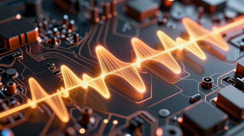
At 77GHz, the signal path on a PCB is no longer a simple conductive trace; it behaves as an intricate electromagnetic waveguide where every transition and substrate characteristic influences transmission efficiency. Signal loss in automotive radar systems is primarily governed by the dielectric constant (Dk) and the dissipation factor (Df) of the substrate material. As frequency increases, electromagnetic waves become increasingly sensitive to the molecular polarization and vibrational modes within the dielectric material, leading to greater energy dissipation as heat.
Dk Stability and Impedance Control
The dielectric constant, or Dk, dictates the propagation speed of the signal. In high-resolution radar, any variation in Dk leads to phase shifts and impedance discontinuities. At 77GHz, even minor variations in substrate thickness or glass-weave uniformity can result in unacceptable phase errors, degrading the radar's ability to resolve small objects at long ranges.
Dissipation Factor and Attenuation
The dissipation factor (Df), or loss tangent, represents the material's ability to store energy versus losing it as thermal radiation. At 77GHz, low Df is non-negotiable. While FR-4 materials are suitable for low-frequency digital signaling, their high Df leads to catastrophic signal attenuation at millimeter-wave frequencies, necessitating the use of specialized PTFE-based or ceramic-filled laminates.
| Parameter | Physical Impact at 77GHz | Design Consideration |
|---|---|---|
| Dielectric Constant (Dk) | Affects phase velocity and impedance | Requires strict Dk tolerance/homogeneity |
| Dissipation Factor (Df) | Causes signal attenuation/heat loss | Mandates low-loss PTFE/LCP substrates |
| Surface Roughness | Increases resistive loss (Skin Effect) | Utilizes Very Low Profile (VLP) copper |
- Why does glass weave matter at 77GHz?
The glass weave pattern in traditional PCB laminates creates local Dk variations. At high frequencies, these microscopic changes cause signal skew and phase inconsistencies that directly impact radar accuracy. - Is Df more important than Dk?
Both are critical; however, Df is the primary determinant of signal amplitude loss over distance, while Dk management is crucial for timing synchronization and pulse integrity in modulated radar signals.
Evaluating Advanced Substrate Materials
PTFE-Based Laminates: The Benchmark for High-Frequency Precision
Polytetrafluoroethylene (PTFE)-based laminates have long served as the industry standard for high-frequency applications, primarily due to their exceptionally low dissipation factor (Df). In the context of 77GHz automotive radar, PTFE substrates minimize signal attenuation, allowing for longer transmission distances and improved sensor sensitivity. However, their low modulus and high coefficient of thermal expansion (CTE) introduce manufacturing challenges, particularly when considering the mechanical stresses inherent in under-the-hood automotive environments.
Hydrocarbon-Ceramic Composites: Enhancing Mechanical Robustness
Hydrocarbon-ceramic composites offer an optimized middle ground, combining the stable dielectric properties required for high-frequency signal propagation with superior mechanical rigidity. These substrates address the CTE mismatch issues often found in pure PTFE designs, providing better reliability during thermal cycling. Their ability to be processed using standard FR-4 manufacturing techniques makes them an increasingly attractive option for high-volume, cost-sensitive automotive radar production lines.
Material Property Comparison
| Parameter | PTFE-Based | Hydrocarbon-Ceramic |
|---|---|---|
| Dissipation Factor (Df) | Ultra-Low (0.0009) | Low (0.002) |
| Dielectric Constant (Dk) Stability | Excellent | Good |
| Mechanical Rigidity | Low | High |
| Thermal Expansion (CTE) | Higher (Difficult) | Low (Manageable) |
| Fabrication Complexity | High | Moderate |
Frequently Asked Questions
- Why is the CTE of the substrate critical for automotive radar?
Automotive radar sensors endure significant temperature fluctuations. A substrate with a high CTE mismatch relative to copper or components can lead to solder joint fatigue and via cracking over the vehicle's lifespan. - Does the lower Df of PTFE outweigh the manufacturing advantages of hydrocarbon-ceramics?
For long-range radar requiring maximum signal reach, the performance benefits of PTFE are often indispensable; however, for short-range sensors in high-volume mass production, hydrocarbon-ceramics offer a better balance of reliability and cost-effectiveness.
Thermal Management and Coefficient of Thermal Expansion (CTE)
Thermal Stability and Radar Precision
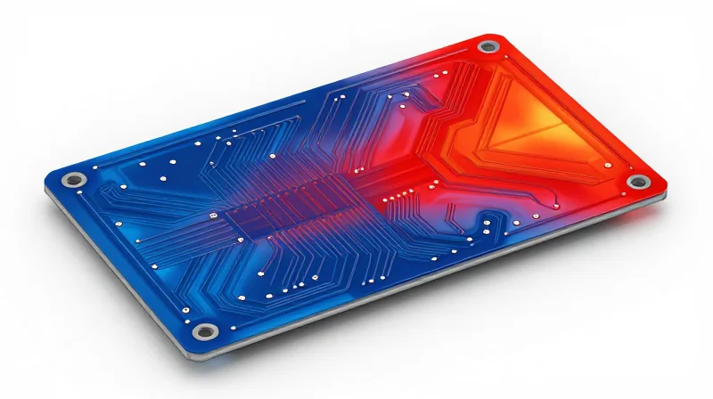
As automotive radar systems transition to 77GHz and higher frequencies, the precision of signal propagation becomes inextricably linked to the structural integrity of the PCB substrate. In an automotive environment, sensors are subject to extreme temperature swings—ranging from frigid winter starts to intense engine heat. Any deviation in the substrate's dimensions or dielectric properties under these conditions directly impacts the phase stability and antenna gain of the radar system, potentially leading to ghosting or target misidentification in ADAS applications.
CTE Mismatch and Reliability
The Coefficient of Thermal Expansion (CTE) measures the rate at which a material expands or contracts with temperature changes. In a multi-layer PCB, a mismatch between the CTE of the dielectric substrate, the copper layers, and the surface-mount components creates significant internal stresses. Over thousands of thermal cycles, this stress leads to micro-cracking in vias and delamination of copper traces. For autonomous safety systems, such failures are non-negotiable; therefore, selecting materials with a low, uniform CTE is a critical engineering requirement.
| Material Type | CTE (ppm/°C) Z-Axis | Thermal Performance | Typical Use Case |
|---|---|---|---|
| Standard FR-4 | 300-400 | Poor (Low Tg) | Infotainment |
| PTFE-Based | 150-250 | Moderate | High-Frequency Antennas |
| Hydrocarbon-Ceramic | 30-60 | Excellent | ADAS Radar Sensors |
Common Thermal Management Challenges in Radar PCBs
- How does temperature affect Dk?
As temperature increases, the Dielectric Constant (Dk) of most substrates shifts, causing frequency drift. High-stability materials are engineered to minimize this 'thermal coefficient of dielectric constant' to keep radar signals calibrated. - Why is Z-axis CTE critical?
Thermal expansion in the Z-axis is the primary cause of plated through-hole (PTH) barrel fatigue and cracking during extreme thermal cycling. - Does CTE matching extend to components?
Yes, matching the substrate CTE as closely as possible to the copper foil and ceramic chip carriers reduces mechanical strain on solder joints, ensuring long-term interconnect reliability.
Manufacturing Challenges for Next-Gen ADAS
Mitigating Insertion Loss at 77GHz
As automotive radar shifts toward 77GHz and beyond, the skin effect becomes a dominant factor in signal degradation. At these frequencies, the majority of the current flows through the outermost layer of the copper conductor, meaning the surface profile of the foil directly impacts total insertion loss.
The Impact of Copper Foil Surface Roughness
While high-profile copper foil provides superior mechanical peel strength—essential for high-vibration automotive environments—the rough surface acts as a series of obstacles for high-frequency electrons. This surface impedance increases attenuation. Engineers must balance the trade-off between mechanical adhesion and electrical performance.
| Copper Type | Surface Profile (Rz) | Insertion Loss Impact | Adhesion Quality |
|---|---|---|---|
| Standard Electro-Deposited (ED) | High (4-6 µm) | Significant | Excellent |
| Low Profile (LP) | Medium (2-3 µm) | Moderate | Good |
| Very Low Profile (VLP/HVLP) | Low (<1.5 µm) | Minimal | Moderate |
Manufacturing Considerations for Radar Modules
- How does foil selection affect fabrication?
Switching to VLP or HVLP copper for radar traces requires specialized surface treatment processes during PCB etching to ensure the resist maintains adequate adhesion to the smoother copper surface. - Why is trace uniformity critical?
At 77GHz, even minute variations in trace width or etched copper sidewall roughness cause impedance discontinuities that manifest as signal reflections and phase errors in radar sensing. - What role do multi-stage etching processes play?
To maintain high-precision geometry while utilizing advanced laminates, manufacturers are increasingly adopting direct imaging and multi-stage controlled-depth etching to minimize undercut and maintain strict 50-ohm impedance control.
Emerging Design Trends in Radar Integration

The Evolution of Antenna-in-Package (AiP) Technology
Antenna-in-Package (AiP) represents the most significant shift in radar module design. By integrating the antenna array directly into the chip packaging or the immediate substrate layer, engineers can virtually eliminate transmission line losses between the transceiver and the antenna. This design choice is crucial for 77GHz and 79GHz systems, where the proximity of signal paths is the primary determinant of system-wide link budget success.
Transitioning to Multi-Layer Hybrid Substrates
Modern automotive radar requires a complex balancing act between high-frequency RF performance and reliable power delivery. The adoption of hybrid substrate stacks—combining high-frequency PTFE laminates for RF signal layers with standard FR-4 or high-Tg glass-reinforced resins for control logic—allows for cost-effective manufacturing without sacrificing performance in critical sensing zones.
| Integration Strategy | Primary Advantage | Thermal Impact |
|---|---|---|
| AiP (Antenna-in-Package) | Minimized RF path loss | High localized heat flux |
| Embedded Components | Reduced parasitic inductance | Improved heat dissipation |
| Hybrid Substrates | Optimized cost vs. signal | Balanced CTE expansion |
Technical FAQs on Radar Integration
- Why is embedded component technology becoming standard?
Embedding passive components directly into the PCB substrate reduces the number of surface-mount devices, which decreases parasitic inductance and improves high-frequency response in compact radar modules. - How do substrate trends affect manufacturing complexity?
The move toward thinner, multi-layer designs requires stricter laser-drilling tolerances and advanced surface-finish technologies to ensure consistent signal integrity across high-speed digital and high-frequency analog layers.
Sustainability and Regulatory Compliance
Regulatory Compliance and ISO 26262 Integration
In the automotive industry, compliance is non-negotiable. For ADAS radar systems, materials must align with ISO 26262 functional safety requirements. Substrate selection directly impacts the reliability of the safety-critical sensing chain; any material degradation over the vehicle's lifespan can lead to hazardous failure states. Engineers must prioritize substrates with high Dielectric Strength and proven long-term performance under automotive-grade thermal cycling to ensure they meet Automotive Safety Integrity Level (ASIL) D requirements.
Environmental Sustainability and Material Selection
Modern PCB design must balance high-frequency performance with environmental stewardship. As OEMs strive for carbon neutrality, the supply chain for radar substrates is shifting toward halogen-free materials and processes that reduce hazardous substance usage (RoHS/REACH compliance). The transition to high-performance hydrocarbon-ceramic composites is being optimized to minimize chemical waste during the etching and plating phases, aligning technical high-speed performance with global environmental standards.
| Requirement Category | Compliance Driver | Strategic Impact |
|---|---|---|
| Functional Safety | ISO 26262 / ASIL-D | Ensures reliable sensor signal integrity for critical autonomy. |
| Material Hazard | RoHS / REACH | Mandates restriction of hazardous additives in PCB production. |
| Thermal Reliability | AEC-Q100/AEC-Q200 | Validates long-term stability under severe automotive temperature profiles. |
FAQs: Regulatory and Sustainability Trends
- How does substrate choice impact ISO 26262 certification?
Substrate choices affect signal-to-noise ratios and physical durability; poor material aging can lead to unexpected radar drift, which complicates the safety case for ASIL-D systems. - Are there conflicts between high-speed performance and sustainability?
Historically, yes, as high-performance resins often required halogenated flame retardants, but new-age hydrocarbon-ceramic formulations are successfully decoupling these requirements. - What is the role of material traceability in radar PCBs?
Traceability is vital for recall management and ensuring that only qualified, tested material lots are used in critical ADAS sensing infrastructure.
Transitioning to 77GHz and beyond requires a holistic approach to material selection, balancing performance, reliability, and cost-efficiency. By optimizing your PCB substrate strategy today, you ensure the safety and reliability of tomorrow’s autonomous platforms. Partner with our engineering experts to select the right materials for your next-generation radar designs—contact us today for a technical consultation.
