
As the automotive industry pivots toward zonal and domain-based architectures, the Telematics Control Unit (TCU) has evolved from a simple connectivity module into the high-speed nerve center of the vehicle. With the surge in V2X data and autonomous processing needs, legacy PCB materials are struggling to keep pace. This article examines why the migration to advanced high-frequency PCB solutions is no longer a luxury, but a fundamental requirement for the software-defined vehicle.
The Evolution of TCU Architecture
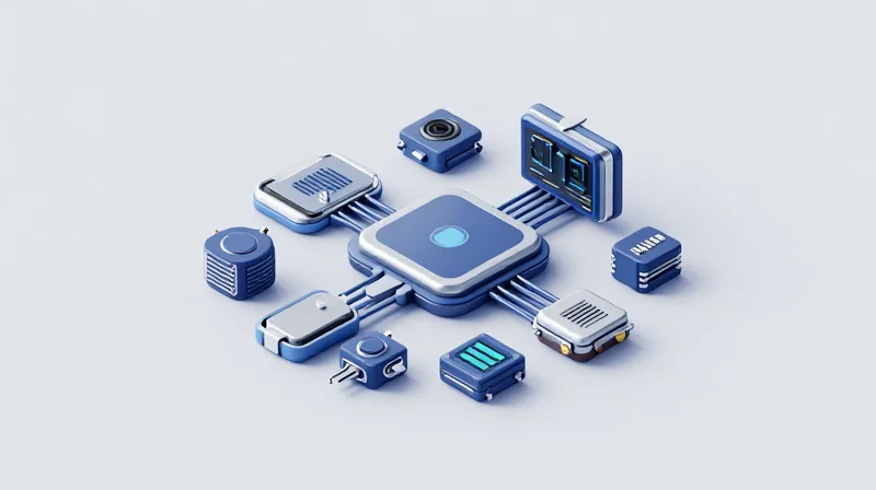
From Stand-alone Modules to Domain Integration
Historically, the TCU functioned as an independent, isolated gateway responsible for basic cellular connectivity and emergency calling services. In this legacy architecture, the TCU relied on standard FR-4 PCB materials and discrete components, as data throughput requirements were low and latency was not a critical constraint. As vehicle architectures move toward Software-Defined Vehicle (SDV) paradigms, these stand-alone modules are rapidly being consolidated into centralized cockpit or connectivity domain controllers. This transition demands a radical shift in board design to support 5G, V2X (Vehicle-to-Everything), and high-speed data processing.
| Feature | Legacy TCU Architecture | Next-Gen Domain Controller |
|---|---|---|
| Connectivity | 4G LTE / GSM | 5G NR / V2X / Wi-Fi 6E |
| Architecture | Stand-alone / Decentralized | Integrated Domain/Zonal |
| PCB Material | Standard FR-4 | High-Frequency Laminates (Low Loss) |
| Processing | Basic Microcontroller | System-on-Chip (SoC) / NPU |
Technological Drivers of Change
- Signal Integrity Demands
The jump to mmWave and sub-6GHz 5G frequencies necessitates low-loss PCB substrates to mitigate signal attenuation and cross-talk, which were non-issues in earlier cellular standards. - Thermal Management
Higher computational loads for real-time processing and high-bandwidth data routing require enhanced thermal dissipation strategies integrated directly into the multi-layer stack-up of the PCB. - Miniaturization
Space constraints within vehicle architecture force the integration of RF and baseband circuits onto smaller footprints, requiring high-density interconnect (HDI) technologies.
The Performance Bottleneck: Why Legacy PCBs Fall Short

The Impedance and Loss Problem
Traditional TCU designs have long relied on FR4 (Flame Retardant 4) laminates due to their cost-effectiveness and mechanical stability. However, as automotive connectivity shifts toward 5G frequencies and V2X (Vehicle-to-Everything) communications, the dielectric loss tangent and inconsistent dielectric constants of FR4 create significant signal attenuation. At higher gigahertz frequencies, the signal energy is absorbed into the substrate as heat, resulting in degraded signal integrity and increased bit error rates that compromise mission-critical latency.
Performance Comparison: FR4 vs. High-Frequency Laminates
| Parameter | Standard FR4 | High-Frequency Laminate |
|---|---|---|
| Dielectric Constant (Dk) | Higher/Variable | Low/Stable |
| Loss Tangent (Df) | High (>0.020) | Ultra-Low (<0.003) |
| Frequency Range | Sub-1GHz optimized | 5GHz to 77GHz+ |
| Thermal Conductivity | Poor | Excellent |
Thermal and Signal Integrity FAQ
- Why does signal attenuation matter in automotive TCUs?
As data throughput requirements for autonomous driving grow, signal loss directly translates to packet corruption, requiring intensive error correction that increases system latency. - How does PCB heating affect reliability?
Excessive heat leads to board warping and copper trace oxidation, which, over thousands of cycles in extreme vehicle temperature environments, causes intermittent connectivity failures. - Are there hybrid solutions available?
Yes, many manufacturers utilize 'hybrid builds,' which combine standard FR4 for low-speed logic layers with high-frequency laminates for critical antenna and RF routing.
Advanced PCB Materials for 5G and V2X
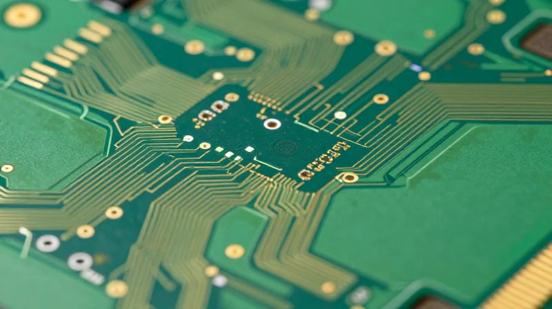
Moving Beyond FR4: Material Requirements for High-Frequency Signal Integrity
As automotive connectivity shifts toward mmWave 5G frequencies and sub-6GHz V2X applications, traditional FR4 materials encounter insurmountable signal integrity degradation. At frequencies exceeding 6GHz, the dielectric loss (Df) and the variance in the dielectric constant (Dk) of standard epoxies lead to significant signal attenuation and phase distortion. High-frequency applications require materials with extremely low Df (typically <0.003) and stable Dk across wide temperature ranges to maintain impedance control and minimize transmission losses.
Key Material Categories for Next-Gen Connectivity
| Material Type | Key Advantage | Primary Application |
|---|---|---|
| PTFE-based Laminates | Ultra-low dielectric loss | High-speed RF front-ends |
| Ceramic-filled Resins | Excellent thermal stability/Dk control | V2X antennas and transceivers |
| Modified Polyphenylene Ether (mPPE) | Cost-effective signal performance | Integrated domain controllers |
PTFE-based laminates remain the gold standard for high-performance RF circuit boards due to their exceptional dielectric properties. However, their physical softness and high thermal expansion coefficient present challenges during assembly. Ceramic-filled hydrocarbon resins offer a more robust alternative, providing a balanced profile of lower signal loss while maintaining structural integrity required for the demanding automotive environment.
Frequently Asked Questions Regarding Advanced Substrates
- Why is the dielectric constant (Dk) stability critical in V2X PCBs?
Automotive V2X systems must operate reliably under extreme ambient conditions. Dk stability ensures that signal impedance remains constant, preventing reflections and maintaining accurate data transmission rates. - Can multi-layer stack-ups combine traditional materials with high-frequency laminates?
Yes, through hybrid PCB construction. Engineers use high-performance laminates in the outer layers to handle high-frequency routing, while utilizing lower-cost FR4 materials for internal power and signal planes to balance performance and cost. - How do advanced materials impact thermal management?
Many high-frequency substrates are designed with higher thermal conductivity than standard resins, assisting in the passive dissipation of heat from densely packed 5G power amplifiers.
Thermal Management in High-Density Architectures
Overcoming Thermal Density Challenges
As TCUs evolve into centralized domain controllers, power density has surged, placing unprecedented thermal stress on compact enclosures. Traditional PCB manufacturing methods, often reliant on standard epoxy-based prepregs, struggle to dissipate heat effectively in high-frequency regimes where thermal conductivity and dielectric stability are linked. Modern thermal management requires a multi-layered strategy involving advanced substrate selection, thermal vias, and sophisticated structural interface materials (TIMs).
Comparative Analysis of Thermal Performance
| Material Type | Thermal Conductivity (W/mK) | Suitability for High Density | Key Advantage |
|---|---|---|---|
| Standard FR4 | 0.25 - 0.35 | Low | Cost Efficiency |
| High-Tg FR4 | 0.40 - 0.50 | Moderate | Improved Thermal Stability |
| Ceramic-Filled Laminates | 0.80 - 2.50 | High | Superior Dissipation |
| Metal Core PCBs (IMS) | 2.00 - 4.00+ | Very High | Direct Heat Pathing |
Thermal Engineering Strategies
To mitigate local hotspots, design engineers are shifting away from passive heat sinks toward integrated thermal management solutions. Implementing high-density interconnect (HDI) structures with copper-filled thermal via arrays allows for efficient vertical heat transport through the PCB core. When paired with high-frequency-optimized substrates, these pathways ensure that the thermal expansion coefficients (CTE) remain stable, preventing micro-cracking during rapid thermal cycling.
- How do ceramic-filled laminates improve thermal performance?
They provide a higher thermal conductivity than traditional organic resin systems, facilitating faster heat removal from high-power integrated circuits while maintaining consistent dielectric constants. - What is the role of CTE matching in high-density TCUs?
Matching the Coefficient of Thermal Expansion between PCB materials and components prevents mechanical stress on solder joints, which is vital for the 15-year operational life cycles required in automotive environments. - Can thermal vias negatively impact signal integrity?
If not properly designed, high concentrations of thermal vias can introduce parasitic capacitance or inductance; however, optimized via-stitching patterns can improve both thermal pathways and signal shielding.
Signal Integrity and Electromagnetic Compatibility (EMC)

As automotive telematics units (TCUs) transition to support 5G, V2X, and multi-gigabit data streams, the challenges surrounding Signal Integrity (SI) and Electromagnetic Compatibility (EMC) intensify significantly. Maintaining signal fidelity requires a shift from heuristic-based routing toward rigorous impedance control and meticulous layer stack-up optimization to suppress crosstalk, mitigate EMI, and ensure compliance with stringent automotive standards.
Best Practices for High-Speed Routing
High-frequency signal paths are highly susceptible to discontinuities caused by vias, stubs, and trace geometry changes. Engineers must prioritize the following design methodologies to maintain signal integrity:
- Controlled Impedance Routing
Utilize differential pair signaling with tightly coupled traces and strictly controlled stack-up geometries to minimize reflections and maintain target impedance, typically 90 or 100 ohms for high-speed buses. - Via Transition Optimization
Minimize via length to reduce parasitic capacitance and inductance; employ back-drilling to eliminate unused via stubs that create resonant frequencies, effectively acting as unintended antennas. - Return Path Continuity
Ensure an unbroken reference plane beneath high-speed signals. Avoid routing signals across plane splits or voids, which forces return currents to take indirect paths, significantly increasing loop area and EMI radiation.
Stack-Up Strategies for EMC Mitigation
The PCB stack-up is the foundational element of EMC compliance. For next-gen TCU architectures, a symmetrical, multi-layer approach is non-negotiable to balance thermal distribution and electromagnetic shielding.
| Design Factor | Legacy Approach | Next-Gen High-Frequency Strategy |
|---|---|---|
| Plane Configuration | Simplified ground/power planes | Dedicated ground layers for signal referencing |
| Trace Separation | Rule-of-thumb spacing | Calculated 3H-rule to minimize coupling |
| EMI Mitigation | Enclosure-based shielding | Internal stitching vias and buried capacitance |
Addressing Common SI/EMC Challenges
- How do board materials impact SI?
Higher frequency signals experience higher dielectric loss (Df). Transitioning to ultra-low-loss laminates reduces signal attenuation and prevents phase jitter, which is critical for 5G data rates. - Why is Crosstalk critical at higher speeds?
As rise times decrease, electromagnetic coupling between adjacent traces increases. Designers must increase trace spacing or utilize guard traces, while ensuring that the coupling is contained within the intended differential pair.
Reliability in Harsh Automotive Environments
Durability Under Extreme Conditions
Automotive Telematics Control Units (TCUs) operate in some of the most demanding physical environments in the electronics industry. Unlike consumer devices, automotive-grade PCBs must withstand continuous thermal cycling, extreme moisture exposure, and constant high-frequency vibration without succumbing to fatigue, delamination, or interconnect failure.
| Environmental Stressor | Traditional PCB Impact | High-Frequency Solution |
|---|---|---|
| Thermal Cycling | Copper barrel fatigue | Low CTE substrate materials |
| Mechanical Shock | Solder joint fractures | Reinforced fiber weave structures |
| Moisture Absorption | Dielectric constant drift | Hydrophobic resin systems |
Material Science for Long-Term Reliability
To achieve a design life cycle exceeding 15 years, engineers are shifting toward high-frequency laminates that offer a low Coefficient of Thermal Expansion (CTE). These materials ensure that the expansion rate of the PCB matches that of the copper cladding and surface-mounted components, drastically reducing the mechanical strain on solder joints during severe temperature swings common in engine-bay or exterior-integrated locations.
Reliability FAQ
- How do vibration profiles affect TCU connectivity?
Constant mechanical stress can cause trace micro-cracks or solder joint fatigue. Advanced boards use specialized glass-weave architectures to improve mechanical rigidity and dampening. - Why is moisture absorption critical for 5G performance?
Moisture ingress changes the dielectric constant of the PCB, which shifts impedance and leads to signal attenuation. Next-gen materials utilize low-loss resins that are inherently hydrophobic. - Does higher frequency impact environmental durability?
Yes, because higher-speed designs require tighter tolerances and finer traces. Any physical deformation due to environmental stress has a more pronounced impact on high-frequency signal integrity than on legacy low-speed systems.
Cost vs. Performance: Strategic Sourcing for OEMs
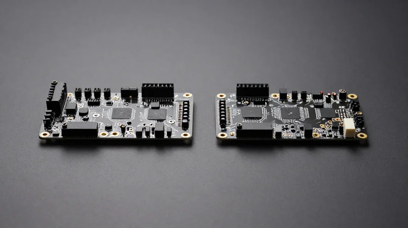
As automotive architectures shift toward 5G, V2X, and autonomous driving, the demand for high-performance PCBs has outpaced traditional manufacturing capabilities. OEMs must transition from a cost-per-unit mindset to a Total Cost of Ownership (TCO) model that accounts for signal integrity, thermal dissipation, and long-term reliability.
Cost-Performance Matrix: Material Selection Strategy
| PCB Technology | Performance Level | Cost Premium | Ideal Application |
|---|---|---|---|
| Standard FR-4 | Low | Baseline | Basic Infotainment |
| High-Tg/Modified Epoxy | Moderate | 1.2x - 1.5x | Standard Telematics |
| PTFE/Ceramic Filled | High | 2.5x - 4x | ADAS, V2X, 5G Antennas |
Strategic Sourcing FAQ
- How can OEMs mitigate the higher cost of PTFE-based materials?
OEMs can utilize hybrid board construction, where only the high-frequency signal layers use expensive PTFE laminates, while standard materials are used for power and ground planes to reduce overall material consumption. - Does higher PCB cost always translate to higher vehicle cost?
Not necessarily. Investing in high-frequency materials at the design phase can reduce the need for bulky shielding, external cooling hardware, and complex signal repeaters, leading to a more streamlined and cost-effective overall assembly. - What is the primary risk of selecting lower-cost PCB materials for next-gen connectivity?
Signal degradation and packet loss are the primary risks, which directly impact the safety-critical latency requirements of V2X systems, potentially leading to expensive warranty recalls and brand reputation damage.
The strategic selection of PCB materials must align with the vehicle's functional safety classification. For Tier 1 and Tier 2 suppliers, building a resilient supply chain requires close collaboration with material suppliers to secure stable pricing for specialized laminates while optimizing layout designs for mass-manufacturing scalability.
The Road Ahead: Future-Proofing Automotive Connectivity
The Shift Toward Centralized Zonal Architectures
As vehicles transition from domain-based architectures to centralized zonal controllers, the role of the Telematics Control Unit (TCU) is fundamentally changing. The future-proof connectivity suite relies on high-speed data backbones that require PCB substrates capable of handling multi-gigabit throughput while maintaining signal integrity across longer physical traces.
Comparison of Hardware Evolution
| Feature | Legacy TCU PCB | Next-Gen High-Frequency PCB |
|---|---|---|
| Signal Frequency | Sub-6 GHz | mmWave / High-Band 5G |
| Material | Standard FR-4 | Low-Loss Laminates (PTFE/Ceramic) |
| Thermal Management | Basic Heat Sinks | Integrated Micro-Vias & Copper Inlays |
| Scalability | Fixed Function | Modular/Software-Defined |
Critical Engineering Considerations for 2025 and Beyond
- How does PCB material selection impact 5G connectivity?
As frequencies move into the mmWave spectrum, dielectric constant (Dk) and dissipation factor (Df) become critical. Next-gen boards must utilize advanced PTFE-based laminates to minimize signal attenuation. - What is the role of integration in hardware longevity?
Hardware must support OTA (Over-the-Air) updates not just for software, but for communication protocols. Future-proofing requires modular hardware designs that allow for RF front-end swaps without replacing the entire control module. - How will EMI shielding change in high-density layouts?
Increased component density requires advanced board-level shielding (BLS) and sophisticated via-fencing strategies to prevent cross-talk in dense high-speed digital zones.
Strategic Implementation Framework
To remain competitive, OEMs must prioritize collaboration between PCB manufacturers and RF engineers early in the design cycle. Implementing a 'design-for-test' approach that accounts for high-frequency signal propagation will be the deciding factor in reducing time-to-market for connected autonomous vehicles.
To thrive in the era of autonomous and electrified mobility, hardware engineers must prioritize advanced high-frequency materials that guarantee signal integrity and system reliability. By moving away from legacy limitations, OEMs can ensure their vehicles remain at the cutting edge of connectivity. Contact our engineering team today to discuss your next-generation TCU project and optimize your hardware for the future.
