
The automotive interior is transforming from a collection of fragmented gauges into a unified, glass-cockpit experience. As consumer expectations for smartphone-like fluidity and bezel-less displays rise, traditional modular display architectures are hitting a technological wall. Today, we explore how engineers are pivoting to integrated, high-density PCB designs to solve complexity, reduce latency, and redefine the driving experience.
The Death of Modular: Why Legacy Architectures Struggle
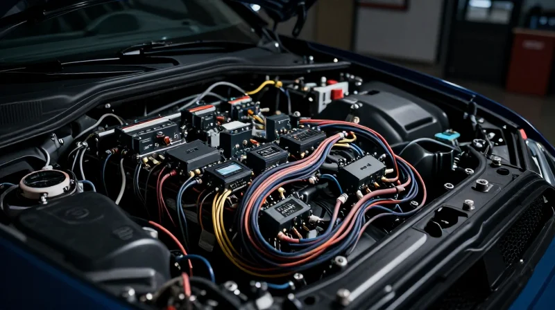
Traditional modular display systems, which rely on decentralized processing units and discrete interconnects between screens, have reached a point of diminishing returns. While these architectures once offered flexibility in component procurement, the current era of high-fidelity cockpit interfaces demands a level of data throughput and temporal synchronization that modular designs can no longer provide effectively.
The Architectural Bottlenecks of Modular Design
| Challenge | Impact on Modular Architectures |
|---|---|
| Latency | Multi-stage signal processing across cables creates frame-timing gaps. |
| Synchronization | Independent display controllers struggle to align content across a visual field. |
| Mechanical Bulk | Excessive cabling and enclosure weight reduce space efficiency. |
| Reliability | Higher count of mechanical connectors increases points of failure. |
Latency and Synchronization Challenges
In a modular setup, every screen acts as an autonomous node with its own controller. This distribution leads to a breakdown in synchronous rendering. When driving a seamless large-format cockpit experience, slight variations in processing latency between independent modules result in tearing or jitter, which is unacceptable in mission-critical flight environments. Integrated PCB solutions eliminate these variables by employing a unified high-speed bus that feeds a centralized graphics engine, ensuring pixel-perfect alignment across the entire display canvas.
Mechanical Constraints and Integration Costs
Modular displays require robust housing and cabling infrastructure for each unit. As cockpit real estate becomes more premium, the weight and volume of these legacy systems impose significant design constraints. Furthermore, the reliance on proprietary connectors for modular interconnects complicates the assembly process and significantly drives up long-term maintenance costs, as each connector serves as a potential failure point due to thermal cycling and vibration.
- Why do modular systems struggle with high-resolution inputs?
Modular systems rely on individual display controllers which often lack the bandwidth to handle the aggregate data stream required for massive, unified glass-cockpit resolutions. - Is physical weight a primary concern?
Yes. Each modular unit requires a dedicated power supply, housing, and frame, which cumulatively adds significant weight compared to a single, optimized integrated PCB architecture.
Technical Advantages of Unified Large-Format PCBs
Architectural Consolidation via HDI Technology
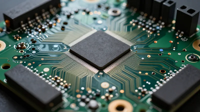
The shift toward unified large-format PCBs is underpinned by advanced High-Density Interconnect (HDI) manufacturing. By utilizing micro-vias and thinner, high-performance substrate materials, engineers can route complex high-speed signaling across a single massive board. This eliminates the 'bottleneck' created by multiple connectors and external cabling found in modular systems, ensuring consistent signal integrity across the entire display surface.
Performance Metrics: Modular vs. Integrated
| Feature | Modular Displays | Integrated Large-Format PCB |
|---|---|---|
| Signal Path | Inter-board cabling | On-board trace routing |
| Synchronization | Network-dependent | Synchronous clocking |
| Thermal Management | Distributed heat loads | Centralized thermal dissipation |
| Reliability | Connector failure risk | Solid-state robustness |
Strategic Benefits of Single-Board Control
Adopting a unified board approach drastically lowers the total cost of ownership through reduced assembly time and fewer individual components. Furthermore, from an engineering perspective, it simplifies the electromagnetic compatibility (EMC) profile of the cockpit, as there are fewer transition points for EMI noise to enter the system.
Frequently Asked Questions
- How does a unified PCB address synchronization issues?
By housing all display drivers on a single substrate, the design utilizes a shared master clock, eliminating the frame-tearing often seen in multi-processor modular setups. - Does the single-board approach introduce thermal failure risks?
While the heat is localized, modern integrated designs use advanced thermal vias and integrated heat spreaders that provide superior efficiency compared to the scattered thermal bottlenecks of modular assemblies.
Thermal Management in High-Density Display Systems
The Thermal Density Challenge
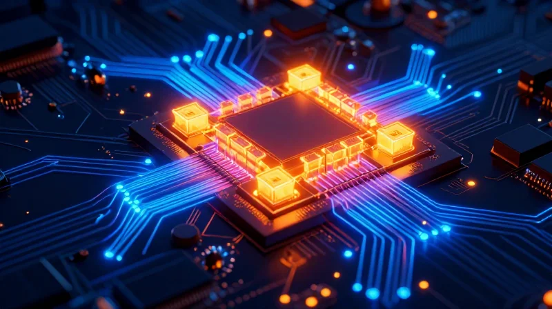
Centralizing high-performance SoCs and graphics processors onto a single large-format PCB exponentially increases heat density compared to distributed modular systems. As display sizes exceed 30 inches and resolution climbs toward 8K, the thermal envelope becomes constrained by the limited space between the display panel and the vehicle chassis, necessitating innovative cooling strategies.
Comparison of Thermal Strategies
| Strategy | Mechanism | Implementation Difficulty |
|---|---|---|
| Active Air Cooling | Forced induction via internal fans | Moderate |
| Phase Change Materials | Absorbing transient thermal spikes | Low |
| Direct-to-Chassis Heat Sinking | Conduction via thermal bridges | High |
| Liquid Cooling Loops | Circulating coolant through manifold | Very High |
Best Practices for Thermal Dissipation
- Why is PCB material selection critical?
Moving from standard FR-4 to high-Tg materials prevents structural warping and thermal degradation of high-speed signal pathways during continuous operation at high temperatures. - How does thermal spreading affect design?
Utilizing copper-heavy internal layers serves as a planar heat spreader, preventing localized 'hotspots' that lead to premature transistor failure within the GPU and display driver ICs. - Can passive cooling support large displays?
Yes, provided the design incorporates structural heat pipes or vapor chambers that bridge the gap between the chip package and the structural frame of the dashboard, essentially turning the chassis into a massive heat sink.
Ultimately, the shift to large-format integrated PCBs mandates a co-design approach where mechanical engineering and electrical design occur in parallel. Engineers must model the heat map across the entire PCB surface to ensure that no single component exceeds the thermal throttling threshold, preserving the user experience in even the most demanding cabin environments.
Data Integrity and Signal Routing Advancements
Optimizing Signal Paths in Unified Architectures
By centralizing processing and display drivers onto a single high-density PCB, engineers effectively eliminate the 'interconnect bottleneck' inherent in traditional modular systems. In legacy designs, signals traversing multiple flexible printed circuits (FPCs) and connectors are susceptible to electromagnetic interference (EMI) and impedance mismatches. Conversely, an integrated approach utilizes unified trace routing, allowing high-speed LVDS or MIPI D-PHY lanes to maintain signal fidelity across shorter, controlled-impedance paths, significantly reducing signal degradation and error-correction overhead.
Signal Performance Comparison
| Feature | Modular Architecture | Integrated PCB |
|---|---|---|
| Signal Path Length | Long (High latency) | Short (Low latency) |
| Connector Reliance | High (Failure point) | Minimal (Direct traces) |
| EMI Susceptibility | High | Low |
| Data Integrity | Moderate | Superior |
Advanced Routing Strategies for High-Resolution Cockpits
Routing high-bandwidth signals for ultra-wide, high-refresh-rate cockpit displays requires sophisticated layout strategies. Modern integrated PCBs utilize multi-layer stack-ups with micro-vias and buried vias to manage high-density routing without sacrificing signal return paths. By optimizing ground plane continuity directly beneath high-speed differential pairs, designers ensure precise impedance control. This reduction in parasitic capacitance is essential for supporting the massive data throughput required by modern 8K and multi-zone infotainment systems.
Frequently Asked Questions on Signal Routing
- How does unified PCB routing reduce total system latency?
By removing intermediate connectors and long cabling, signal flight time is minimized and impedance discontinuities are avoided, allowing for direct communication between the SoC and the display driver. - Why is EMI a concern in modular systems?
Modular cables act as antennas, capturing radiated noise from the vehicle environment. Integrated boards keep traces contained within protected inner layers, significantly lowering EMI emissions and susceptibility. - Does higher integration complicate PCB manufacturing?
Yes, it necessitates advanced HDI (High-Density Interconnect) fabrication, but the trade-off is higher production reliability and lower failure rates in the field due to fewer physical points of failure.
Supply Chain and Manufacturing Efficiency
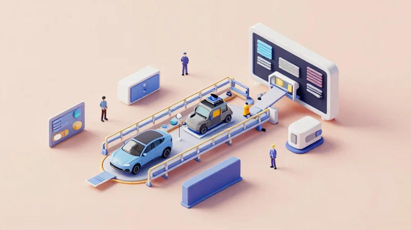
The transition from fragmented, modular display units to integrated large-format PCB solutions represents a paradigm shift in automotive manufacturing. By collapsing multiple discrete control modules into a single, cohesive circuit architecture, manufacturers can eliminate redundant connectors, simplify wire harness complexity, and significantly reduce assembly cycle times on the production line.
Optimizing Assembly and Manufacturing Throughput
Integrated PCB solutions facilitate a 'plug-and-play' assembly approach that replaces labor-intensive wiring with high-speed automated assembly processes. This reduction in component count lowers the probability of assembly errors, improves overall First-Pass Yield (FPY) rates, and optimizes floor space within the assembly plant.
| Metric | Modular Displays | Integrated Large-Format PCBs |
|---|---|---|
| Assembly Time | High (Multi-step integration) | Low (Single-unit mount) |
| Component Count | High (Discrete modules) | Low (Consolidated board) |
| Logistical Complexity | High (Complex SKU management) | Low (Unified procurement) |
| Wiring Harness | Extensive | Minimalist |
Supply Chain and Lifecycle Efficiency
Beyond the factory floor, integrated architectures simplify the supply chain by reducing the number of Tier-2 and Tier-3 suppliers required for a single cockpit display system. This concentration reduces inventory overhead and exposure to component-level fluctuations, ultimately lowering the total cost of ownership (TCO) over the vehicle's lifecycle.
- Does board consolidation improve long-term serviceability?
Yes, by reducing the number of physical interconnects, the failure points associated with mechanical connectors are minimized, leading to higher system-level MTBF (Mean Time Between Failures). - How does this affect quality control?
Quality control becomes more predictable as automated optical inspection (AOI) can verify the entire display control system in one pass, rather than testing disparate modules that may later introduce interface bugs. - What is the impact on lead times?
Standardizing on a unified PCB platform allows for more accurate forecasting, enabling manufacturers to secure critical silicon and substrate inventory more effectively than when managing a multitude of bespoke modular components.
Meeting ASIL Standards with Integrated Designs
Implementing ASIL D Standards in Integrated Systems
Integrating multiple cockpit displays onto a single PCB complicates the Automotive Safety Integrity Level (ASIL) validation process, as failure in one domain must not propagate to safety-critical functions. To achieve ASIL D compliance, designers must employ strict hardware partitioning through hypervisors and hardware-level 'firewalls' that isolate infotainment tasks from instrument cluster metrics and telltales. By consolidating these functions, engineers can leverage unified diagnostic channels, ensuring that latency-sensitive safety signals are prioritized at the silicon level.
Compliance Strategies: Modular vs. Integrated
| Feature | Modular Architecture | Integrated PCB |
|---|---|---|
| Fault Propagation | Physically isolated | Logical isolation required |
| ASIL Validation | Independent per module | System-wide holistic safety case |
| Redundancy | Distributed hardware | Shared resource partitioning |
Common Questions on Safety and Integration
- How is hardware interference managed on a single PCB?
Designers utilize advanced Power Management ICs (PMICs) and independent voltage rails to prevent localized failures from affecting critical safety logic, adhering to ISO 26262 requirements for freedom from interference. - Does integration make ASIL certification harder?
It creates a more complex safety case, but it allows for centralized error detection and logging, which can actually simplify system-wide diagnostics compared to disparate modular units. - What role does the hypervisor play in ASIL compliance?
The hypervisor is critical for maintaining memory and CPU partitioning, ensuring that non-safety infotainment applications cannot crash or override the operating system responsible for safety-critical display functions.
The Role of Advanced Materials and Substrates
Next-Generation Laminate Requirements
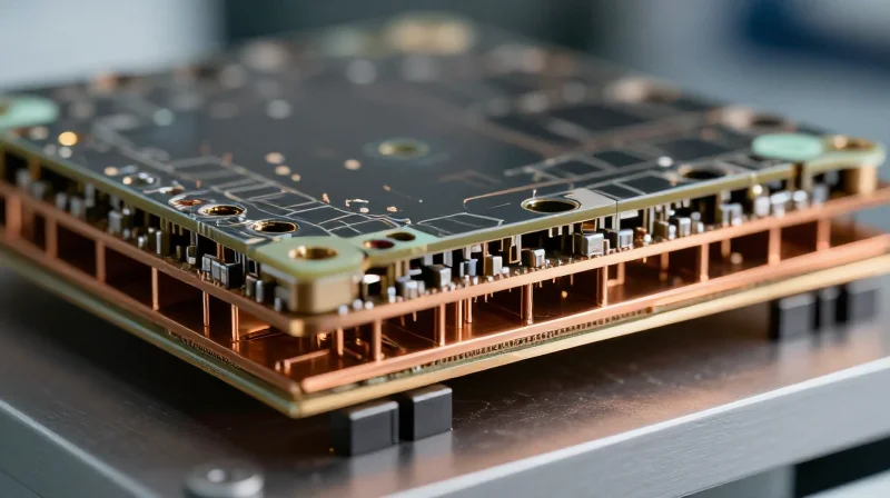
Traditional FR-4 laminates, while cost-effective, struggle to maintain structural integrity and dielectric stability under the extreme temperature fluctuations found in automotive environments. Modern integrated large-format PCBs require high-Tg (glass transition temperature) materials to prevent warping and degradation. Advanced halogen-free, low-loss laminates are now standard, ensuring that high-speed data signals to 4K+ displays remain crisp without succumbing to the signal attenuation common in large-scale modular assemblies.
Copper Weight and Thermal Management
Managing heat dissipation across a single, unified display board requires a strategic approach to copper distribution. Increasing copper weights on internal power planes not only facilitates efficient power delivery but also acts as an essential thermal heat sink. This integration eliminates the need for bulky external cooling modules, directly contributing to the slim profile of modern cockpit electronics.
| Material Feature | Traditional Modular | Integrated Large-Format |
|---|---|---|
| Substrate Base | Standard FR-4 | Advanced High-Tg Laminates |
| Copper Weight | 1oz (Standard) | 2oz+ (High Power Density) |
| Signal Loss | Moderate/High | Ultra-Low Dielectric Loss |
Technical FAQs on Substrate Evolution
- Why is CTE (Coefficient of Thermal Expansion) matching critical?
In large-format boards, the mismatch between the substrate and copper expansion can cause micro-cracks in vias; matching CTE ensures long-term reliability under constant thermal cycling. - How do advanced materials impact EMI?
Modern substrates with specialized filler technologies provide improved electromagnetic interference shielding, which is vital when routing high-speed video data alongside high-power control signals on the same PCB.
Future-Proofing the Digital Cockpit
Architecting for the Software-Defined Vehicle
As the automotive industry pivots toward software-defined vehicles (SDVs), the digital cockpit is no longer a static piece of hardware but a dynamic platform. Future-proofing necessitates a departure from proprietary, fixed-function modules in favor of scalable, high-performance computing clusters capable of over-the-air (OTA) updates and iterative feature deployments.
Strategic Hardware Evolution
| Strategy | Legacy Approach | Future-Proof Approach |
|---|---|---|
| Hardware Lifecycle | Fixed/Static functionality | Modular scalability/Hardware abstraction |
| Update Capability | Firmware-locked/Limited | Containerized OS/OTA-native |
| System Connectivity | Direct/Point-to-point | High-speed zonal architecture/TSN Ethernet |
Managing Technological Obsolescence
The primary risk in cockpit electronics is the delta between vehicle lifespan (10–15 years) and consumer electronic cycles (2–3 years). By moving toward integrated, high-compute PCB architectures that decouple the Human-Machine Interface (HMI) layer from the underlying vehicle control logic, manufacturers can upgrade software stacks without requiring physical display hardware replacement.
- How do integrated PCBs support future-proofing?
They provide a centralized high-speed bus that facilitates easier integration of future sensors and AI accelerators, reducing the need to overhaul the entire wiring harness. - What is the role of abstraction layers?
Software abstraction layers allow application code to remain hardware-agnostic, meaning the same HMI experience can run on newer, more powerful chips as technology evolves. - Can modular displays still be future-proof?
Yes, provided they utilize standardized interfaces (like LVDS or DisplayPort over Ethernet) that allow them to interface with next-generation central compute units seamlessly.
Best Practices for Design Flexibility
To remain competitive, engineers should prioritize high-bandwidth data paths (e.g., PCIe Gen 4/5) on their primary PCBs today to ensure the bandwidth headroom needed for the high-resolution, multi-screen cockpits of tomorrow. Planning for thermal overhead and modular power delivery is equally critical to accommodate next-generation System-on-Chips (SoCs).
As the demand for immersive digital cockpits accelerates, the move toward integrated, high-density PCB solutions is no longer a luxury but a strategic necessity for competitive advantage. By consolidating display architectures, manufacturers can achieve superior performance and reliability. Contact our engineering team today to learn how we can help optimize your next-generation automotive display hardware.
