
The automotive industry is undergoing its most radical architectural transformation in decades. As we transition from legacy domain-based designs to sophisticated zonal architectures, the PCB materials that power our telematics gateways are under unprecedented pressure. From managing high-frequency signal integrity at gigabit speeds to dissipating the intense heat generated by centralized computing modules, engineers face a new frontier of design constraints. This guide evaluates how cutting-edge PCB material trends are evolving to meet these rigorous demands.
The Architectural Shift: From Domain to Zonal

The Architectural Shift: From Domain to Zonal
The transition from traditional domain-based Electronic/Electrical (E/E) architectures to zonal architectures is driven by the massive influx of data necessitated by ADAS, V2X communication, and autonomous driving features. In a domain-based model, telematics gateways functioned as central conduits for specific vehicle functions. In contrast, zonal architecture centralizes data processing into high-performance compute units, with local zones acting as high-speed data collectors. This shift mandates that telematics gateways handle significantly higher data throughput, shifting the focus of PCB design toward extreme signal integrity, lower insertion loss, and improved thermal management.
Material Performance Comparison
| Requirement | Domain Architecture | Zonal Architecture |
|---|---|---|
| Data Rate | Low/Moderate (CAN/LIN) | Ultra-High (Ethernet/SerDes) |
| Signal Loss Sensitivity | Standard FR-4 acceptable | Low-Loss/Ultra-Low-Loss Required |
| Thermal Density | Distributed | High-Concentration |
Frequently Asked Questions
- Why is FR-4 no longer sufficient for zonal gateways?
FR-4 materials exhibit high dielectric loss at the high frequencies required for multi-gigabit automotive Ethernet, leading to signal degradation that prevents reliable high-speed data transmission. - What is the primary material driver in zonal designs?
The primary driver is the necessity for stable Dk (dielectric constant) and Df (dissipation factor) across a wide range of temperatures to ensure consistent signal integrity in harsh under-hood environments.
High-Frequency Challenges in Telematics Gateways

The Impact of 5G and V2X on Signal Routing
As automotive telematics gateways evolve to handle 5G Sub-6 GHz and mmWave frequencies, the physics of signal propagation face unprecedented challenges. Higher frequency operation increases signal attenuation due to conductor losses (skin effect) and dielectric dissipation. To maintain signal integrity, designers must transition from standard FR-4 materials to high-performance laminates with low dissipation factors (Df) and low dielectric constants (Dk). Routing now requires tighter impedance control, where even minor variations in fiber weave patterns or copper surface roughness can lead to significant signal degradation or timing skew.
Dielectric Stability: Managing Thermal and Environmental Stress
Automotive gateways operate in volatile environments where thermal cycling is constant. Traditional substrates often exhibit Dk shifts under high temperatures, which shifts the resonant frequency of high-speed traces and antennas. Next-generation telematics require materials with a near-zero Thermal Coefficient of Dielectric Constant (TCDk). This stability ensures that the phase accuracy of V2X transmissions remains consistent regardless of whether the vehicle is in a cold-start scenario or engine-soaked operation.
| Parameter | Legacy FR-4 | Advanced PTFE/Ceramic Laminates |
|---|---|---|
| Frequency Limit | Up to 2-3 GHz | Up to 80+ GHz |
| Dielectric Loss (Df) | 0.015 - 0.020 | < 0.003 |
| Thermal Stability | Moderate | High (Stable TCDk) |
| Signal Integrity | Low at high speed | Superior for 5G/V2X |
Frequently Asked Questions
- Why is copper surface roughness a critical issue in 5G gateways?
At high frequencies, the skin effect concentrates current on the surface of copper traces. Rough copper profiles increase the effective path length and signal loss, making ultra-low profile (ULP) copper mandatory. - How does fiber weave effect impact signal timing?
The heterogeneous nature of glass-fiber reinforcement creates local Dk variations. As traces run over or between glass bundles, signals experience differing velocities, which can cause significant jitter in high-speed differential pairs. - Can standard automotive boards support V2X requirements?
Generally, no. Standard substrates cannot maintain the required signal fidelity for the low-latency demands of V2X, necessitating the adoption of advanced hydrocarbon or PTFE-based materials.
Comparing Dielectric Material Performance
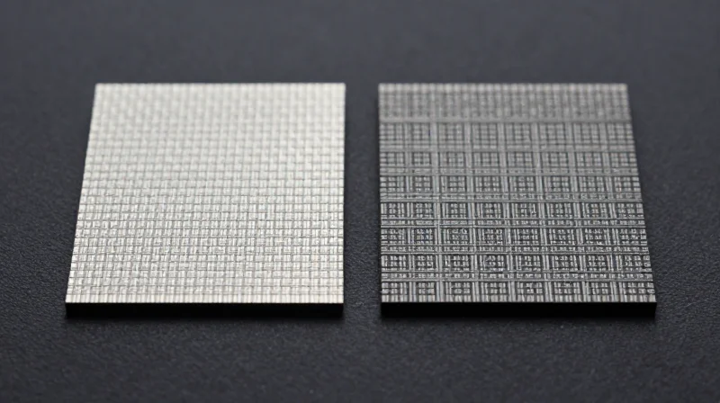
Evaluating Dielectric Material Performance for High-Speed Gateways
As automotive telematics gateways evolve to support multi-gigabit data streams for V2X and 5G connectivity, the choice of PCB substrate has become a primary determinant of system reliability. Engineers must balance dielectric constant (Dk) stability, dissipation factor (Df) losses, and thermal management capabilities to mitigate signal degradation across long routing paths.
| Material Class | Dk Stability | Loss Tangent (Df) | Primary Application |
|---|---|---|---|
| Modified Epoxy | Moderate | 0.005 - 0.010 | Standard gateway routing |
| Hydrocarbon-Based | High | 0.002 - 0.004 | 5G mmWave antennas |
| PTFE-Based | Very High | < 0.002 | High-precision V2X modules |
Critical Performance Trade-offs
- Why is PTFE favored for V2X applications despite higher costs?
PTFE provides the lowest dielectric loss and exceptional thermal stability, which is essential for maintaining signal phase integrity at frequencies exceeding 28GHz. - What are the limitations of modified epoxy laminates?
While cost-effective and easier to manufacture in multi-layer boards, modified epoxies exhibit higher dielectric absorption and Dk fluctuation over temperature, limiting their use in high-frequency signal paths. - How do hydrocarbon laminates bridge the gap?
Hydrocarbon-based materials offer a middle ground, providing superior Dk stability compared to epoxy while being more mechanically robust and easier to process through standard plating lines than PTFE.
The future of automotive architecture necessitates a tiered material approach. By utilizing hybrid stack-ups—combining PTFE for high-frequency signal layers with cost-effective FR-4 or modified epoxy for power distribution and control signals—manufacturers can optimize both the technical performance and the bill of materials cost for next-generation telematics gateways.
Advanced Thermal Management Strategies
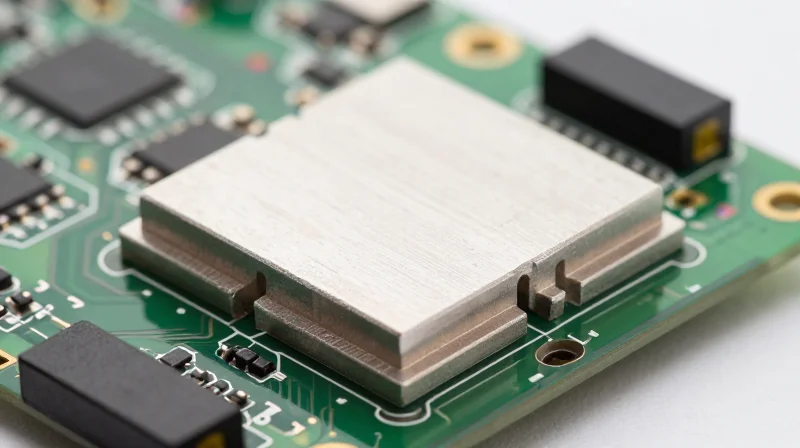
Managing Heat Density in Compact Zonal Architectures
As automotive telematics gateways transition toward centralized zonal architectures, component density is increasing rapidly, leading to significant localized heat flux. Traditional organic substrates often struggle with these thermal loads, necessitating the adoption of advanced materials that facilitate superior heat dissipation without compromising the integrity of high-frequency signal paths.
Material Performance Comparison for Thermal Dissipation
| Substrate Type | Thermal Conductivity (W/m·K) | Primary Application |
|---|---|---|
| Standard FR-4 | 0.25 | Low-power logic |
| High-Tg Thermally Conductive Laminate | 2.0 - 4.0 | Power management modules |
| Aluminum/Copper Core PCB | 150 - 390 | Zonal controller heat sinking |
Implementation of Metallic Core PCBs
Metallic core PCBs utilize a thick copper or aluminum base layer that acts as both a mechanical support and a direct thermal path. By integrating these cores directly into the stack-up, designers can effectively wick heat away from high-switching-frequency processors, preventing localized hotspots that would otherwise lead to dielectric degradation or intermittent signal failure.
Frequently Asked Questions on Thermal Materials
- How do metallic cores impact signal integrity?
While metallic cores excel at thermal dissipation, they introduce parasitic capacitance; careful stack-up design and increased dielectric thickness are required to maintain impedance control for 5G/V2X signals. - When is a thermally conductive prepreg required?
A thermally conductive prepreg is recommended when the power density exceeds the dissipation capacity of copper-filled vias, ensuring a continuous thermal path through the PCB layers.
Signal Integrity and Electromagnetic Compatibility (EMC)
Mitigating Crosstalk in High-Density Automotive Gateways
As automotive telematics gateways transition toward 5G and V2X standards, the density of high-speed differential pairs increases the risk of electromagnetic crosstalk. Mitigating this requires minimizing dielectric absorption and optimizing the weave structure of glass-reinforced laminates. By selecting materials with a stable dielectric constant (Dk) across wide frequency bands, engineers can maintain consistent impedance control, thereby reducing reflection-induced noise and signal degradation between adjacent high-speed traces.
Comparing Shielding Effectiveness and EMC Compliance
| Parameter | PTFE-Based Laminates | Hydrocarbon Ceramics | Modified Epoxy |
|---|---|---|---|
| EMC Performance | Excellent (Low Loss) | Superior (High Stability) | Moderate |
| Crosstalk Resistance | High | Very High | Average |
| Cost Efficiency | Low | Moderate | High |
Strategic EMC Design Considerations
- How does PCB substrate selection impact EMI?
The dielectric dissipation factor (Df) directly affects the magnitude of energy leakage. Materials with ultra-low Df reduce the radiated electromagnetic noise that contributes to system-level EMI. - What is the role of glass-weave style in signal integrity?
The 'fiber weave effect' can cause timing skews in differential signals. Utilizing spread-glass fabrics or non-woven substrates mitigates these localized variations in dielectric constants, ensuring balanced signal propagation. - Can material choice replace physical shielding?
While material choice is critical, it acts as a foundational layer. Effective EMC compliance requires the integration of high-conductivity core materials alongside proper via-stitching techniques to contain internal electromagnetic fields.
To ensure reliable telematics operation, designers must adopt a holistic approach: leveraging low-loss laminates to minimize signal dispersion while implementing robust grounding architectures. This strategy effectively isolates sensitive high-frequency circuits from the broader automotive electrical noise environment.
Reliability Standards for Autonomous-Grade Hardware
Governing Reliability Standards for Automotive Electronics
For next-generation telematics gateways, meeting standard commercial specifications is insufficient. Hardware must conform to stringent automotive-specific frameworks that dictate material composition, signal degradation limits, and mechanical durability. The industry standard IPC-6012 (Automotive Addendum) serves as the baseline, mandating superior laminate adhesion and copper plating integrity to withstand constant thermal cycling and high-frequency vibrations common in vehicle chassis environments.
Key Performance Metrics and Benchmarks
| Benchmark Category | Target Standard | Primary Goal |
|---|---|---|
| Thermal Shock/Cycling | AEC-Q100/AEC-Q200 | Ensure inter-layer via integrity and resin stability. |
| CAF Resistance | IPC-TM-650 | Prevent Conductive Anodic Filament growth. |
| Vibration Tolerance | ISO 16750-3 | Minimize solder joint fatigue in high-density gateways. |
Addressing Material Reliability FAQs
- How does CAF resistance impact material selection?
Conductive Anodic Filament (CAF) growth can lead to catastrophic short circuits. Materials with high glass-transition temperatures (Tg) and reinforced resin systems are prioritized to prevent moisture-induced electrochemical migration. - Why is CTE (Coefficient of Thermal Expansion) critical?
Matching the CTE of the PCB material to the surface-mounted components is essential. Mismatched expansion rates under extreme thermal cycling are the primary cause of solder ball fatigue and mechanical delamination. - Are standard FR-4 materials viable for 5G telematics?
While low-loss FR-4 exists, automotive-grade high-frequency applications often migrate toward PTFE or specialized hydrocarbon laminates because standard resin systems cannot maintain stable dielectric constants over the wide temperature ranges defined in ISO 16750 standards.
By prioritizing materials that exceed these reliability benchmarks, manufacturers can significantly extend the operational lifecycle of telematics gateways, ensuring consistent connectivity in autonomous vehicles where system downtime is not an option.
Cost-Performance Optimization for OEMs
Achieving cost-performance optimization in next-generation telematics gateways requires moving away from a 'one-size-fits-all' material philosophy. As automotive gateways transition toward multi-gigabit data throughput, the necessity for low-loss laminates—traditionally reserved for aerospace or high-end telecommunications—is colliding with the aggressive cost-down pressures of mass automotive production. Successful OEM strategies now focus on selective material usage, where high-performance laminates are localized only to critical RF signal paths, while cost-effective FR-4 or modified-polyimide substrates support lower-speed processing components.
The Material Cost-Performance Matrix
| Material Category | Performance Tier | Cost Index | Best Application |
|---|---|---|---|
| High-Tg FR-4 | Moderate | Low | General Control Logic |
| Modified Epoxy/PPE | High | Medium | Multi-GHz Gateways |
| PTFE/Exotic PTFE | Ultra-High | Very High | Antenna Feedlines |
Strategic Sourcing and Scalability
To maintain scalability, OEMs must prioritize materials that have established supply chains and are compatible with standard assembly processes. The hidden cost of exotic materials often lies in specialized PCB fabrication requirements, such as unique plasma-etching for desmear or specific chemical treatments for copper adhesion. By mandating material compatibility with standard SMT lines, OEMs reduce the risk of assembly defects and shorten the 'time-to-volume' for new gateway platforms.
Frequently Asked Questions on Material Selection
- Can hybrid PCB designs reduce overall costs?
Yes. Hybrid stack-ups allow designers to use expensive low-loss materials only in layers carrying high-speed signals, significantly reducing material waste and cost compared to an all-laminate construction. - Does material choice affect long-term reliability in thermal cycling?
Absolutely. Mismatched Coefficient of Thermal Expansion (CTE) values between exotic materials and copper can lead to via cracking during extreme thermal cycling, necessitating rigorous validation before mass adoption.
Future-Proofing Your Design Infrastructure

Designing for Long-Term Scalability
To future-proof design infrastructure, engineers must move beyond current performance benchmarks and adopt a modular material selection strategy. As automotive telematics gateways transition into high-throughput hubs for autonomous driving data, selecting substrates that offer low dissipation factors (Df) and high thermal stability is no longer optional. These materials provide the necessary signal integrity headroom for future increases in data rates, such as the migration from multi-gigabit Ethernet to future 25Gbps+ automotive SerDes links.
Material Selection Strategy for Hardware Longevity
| Infrastructure Goal | Material Consideration | Future-Proofing Benefit |
|---|---|---|
| High-Bandwidth Scaling | Ultra-Low Loss Laminates | Maintains signal integrity for 5G and V2X upgrades |
| Thermal Resiliency | High Tg/Td Dielectrics | Survives prolonged operation in thermal-constrained zones |
| Software-Defined Support | Advanced Glass Fabric | Reduces skew to support high-speed serial bus expansion |
Frequently Asked Questions
- How do I balance cost with future-proofing?
Utilize hybrid stack-up designs where high-performance materials are restricted to sensitive signal layers, while cost-effective standard FR-4 or mid-loss materials are used for power and ground planes. - Can software updates impact material requirements?
Yes. Future software-defined features often demand higher processing power, which leads to increased thermal output and higher clock frequencies, necessitating superior dielectric reliability over time. - Is there a material standard for future V2X integration?
While no single standard exists, industry leaders are increasingly aligning with IPC-4101 standards for high-speed, high-frequency laminates to ensure consistent performance across diverse vehicle platforms.
Selecting the right PCB material is no longer just a mechanical decision; it is a critical strategic component in defining the capabilities of the autonomous vehicle. By prioritizing signal integrity, thermal efficiency, and long-term reliability, engineers can ensure their telematics gateways remain the backbone of future vehicle connectivity. If you are ready to modernize your hardware design process, contact our engineering experts today to discuss your next project's material requirements.
