In our increasingly electronic world, protecting sensitive components from unpredictable voltage surges is paramount. TVS (Transient Voltage Suppression) diodes act as a critical line of defense, diverting excess energy to prevent damage. This guide explores what makes a TVS diode essential for modern electronics, from its working principles to its wide range of applications, providing you with the understanding to ensure robust and reliable circuit protection.
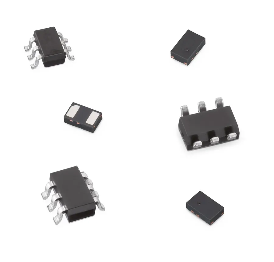
Transient Voltage Suppression (TVS) diodes are semiconductor devices specifically engineered to protect sensitive electronic components from harmful voltage transients. These transients, which include voltage spikes, surges, and electrostatic discharge (ESD), can cause device malfunction, degradation, or even catastrophic failure. TVS diodes act as a first line of defense by quickly shunting excess energy away from protected circuits, ensuring the reliability and longevity of electronic systems.
At the core of their function, TVS diodes exhibit a highly nonlinear resistance characteristic. Under normal operating conditions, they present a very high impedance to the circuit. However, when subjected to a transient voltage that exceeds a predetermined threshold (the breakdown voltage), the diode's impedance dramatically decreases. This allows it to rapidly conduct the excess current, effectively clamping the voltage to a safe level and diverting the surge away from sensitive downstream components. This clamping action is essential for preventing overvoltage damage and ensuring reliable operation of electronic devices.
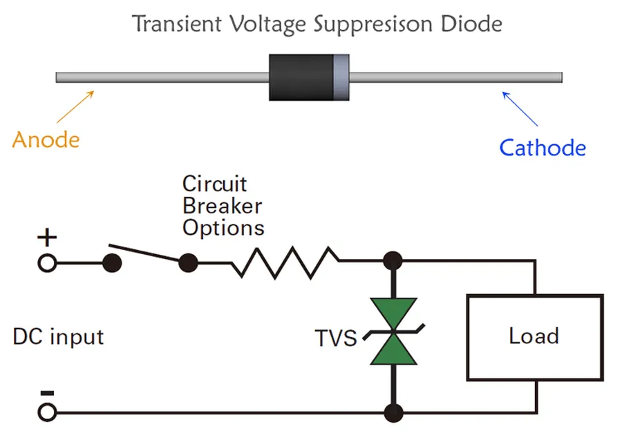
TVS (Transient Voltage Suppression) diodes function as protective devices by rapidly clamping and diverting excess voltage, thus safeguarding sensitive electronic circuits from damaging overvoltage events. This is achieved through a specialized PN junction design that exhibits a very low resistance when a transient voltage exceeds the diode's designed breakdown voltage, allowing it to act as a fast-acting, high-current shunt, effectively diverting the surge current away from the protected components.
The operational mechanism involves the diode’s avalanche or breakdown region. Under normal operating conditions, the TVS diode presents a high impedance to the circuit. When a transient voltage event occurs, exceeding the TVS diode's breakdown voltage (also referred to as the reverse standoff voltage), the diode’s internal resistance rapidly drops. This low resistance path facilitates the diversion of the excess current to ground or another path away from the protected device. Crucially, once the transient voltage subsides, the TVS diode automatically returns to its high-impedance, non-conducting state, ready for the next overvoltage event.
The key to TVS diode's effectiveness lies in its response time and its ability to handle high transient currents. Unlike standard diodes, which can be damaged by large reverse currents, TVS diodes are specifically engineered to endure such currents without damage. This robust clamping action, coupled with the ability to quickly return to a non-conducting state, makes them ideal for protecting sensitive electronics in a wide variety of applications.
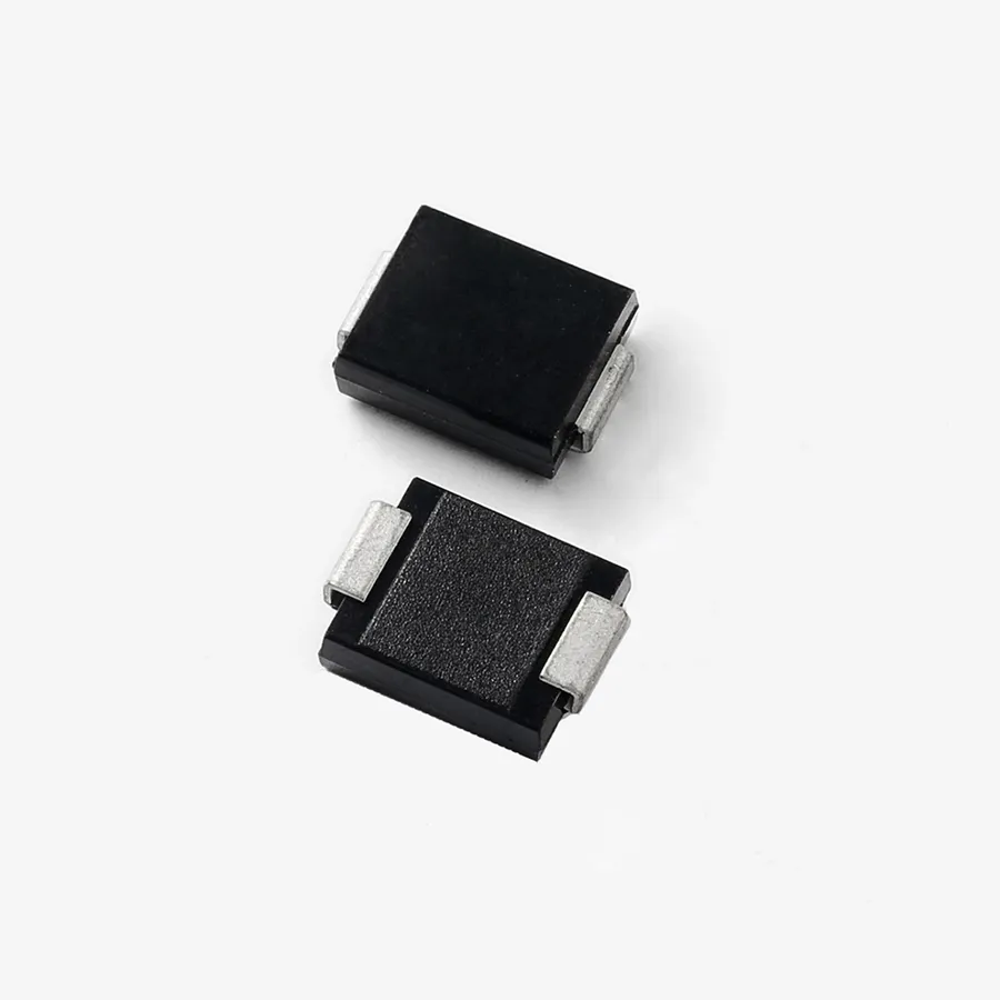
Selecting the appropriate TVS diode requires a thorough understanding of its key characteristics and specifications. These parameters dictate the diode's ability to effectively protect sensitive circuitry from transient voltage events. This section delves into essential specifications like breakdown voltage, clamping voltage, peak pulse power, and response time, providing clarity on their implications for specific applications.
| Parameter | Description | Importance |
|---|---|---|
| Breakdown Voltage (VBR) | The minimum reverse voltage at which the TVS diode starts conducting significantly. This should be higher than the normal operating voltage of the circuit being protected. | Defines the trigger point for protection; must be above normal operating voltage to avoid false triggering. |
| Clamping Voltage (VC) | The maximum voltage that the TVS diode will allow to pass through when conducting under a specified peak pulse current condition. | Indicates the maximum voltage the protected circuit will be exposed to during a transient event; should be below the circuit's tolerance. |
| Peak Pulse Power (PPP) | The maximum power that the TVS diode can handle safely for a given pulse duration. Typically specified for a standard waveform like 8/20 μs. | Crucial for ensuring the diode can dissipate the energy of transient pulses without damage. Must be high enough for anticipated surge levels. |
| Response Time | The time taken by the TVS diode to start clamping the overvoltage. TVS diodes respond very rapidly, typically in picoseconds. | Critical for protecting against fast transients like ESD; a faster response time ensures better protection. |
| Reverse Stand-off Voltage (VRWM) | The maximum reverse voltage the TVS diode can withstand in its non-conducting state, without significant leakage current. | Should be equal to or greater than the normal operating voltage of the protected circuit. Ensures normal operation without the TVS interfering. |
| Capacitance | The parasitic capacitance inherent in the diode. Higher capacitance can cause signal distortion at high frequencies. Affects high frequency applications | Important for high-speed data lines to minimize signal distortion, lower is preferred in these cases. |
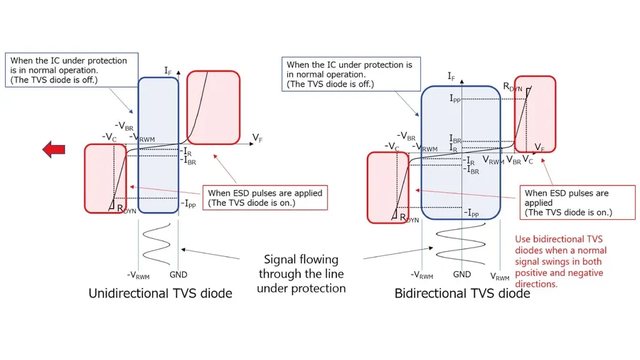
TVS diodes are available in two primary configurations: unidirectional and bidirectional. These classifications denote how the diode responds to voltage transients and subsequently determine their suitability for different circuit protection needs. Understanding the fundamental differences between these types is crucial for selecting the correct component for your application.
| Feature | Unidirectional TVS Diode | Bidirectional TVS Diode |
|---|---|---|
| Voltage Response | Clamps voltages in one polarity only (typically positive relative to ground). | Clamps voltages in both polarities (positive and negative relative to ground). |
| Polarity Sensitivity | Sensitive to the polarity of the transient voltage. Requires proper orientation in the circuit. | Not sensitive to the polarity of the transient voltage. Can be placed in either direction. |
| Construction | Usually a single P-N junction diode. | Effectively two P-N junction diodes connected back-to-back. |
| Application | Used in DC circuits where the transient voltage is expected to have a consistent polarity, and also can be used in AC circuit with the proper circuit design. | Ideal for AC circuits or applications where the polarity of the transient voltage is unknown or can vary. |
| Cost | Generally less expensive. | Usually more expensive. |
The selection between unidirectional and bidirectional TVS diodes hinges on the nature of the circuit being protected. Unidirectional diodes are suited for DC applications with a predictable transient polarity, while bidirectional diodes excel in AC or unpredictable polarity scenarios, providing a robust defense against a wider range of voltage surges.
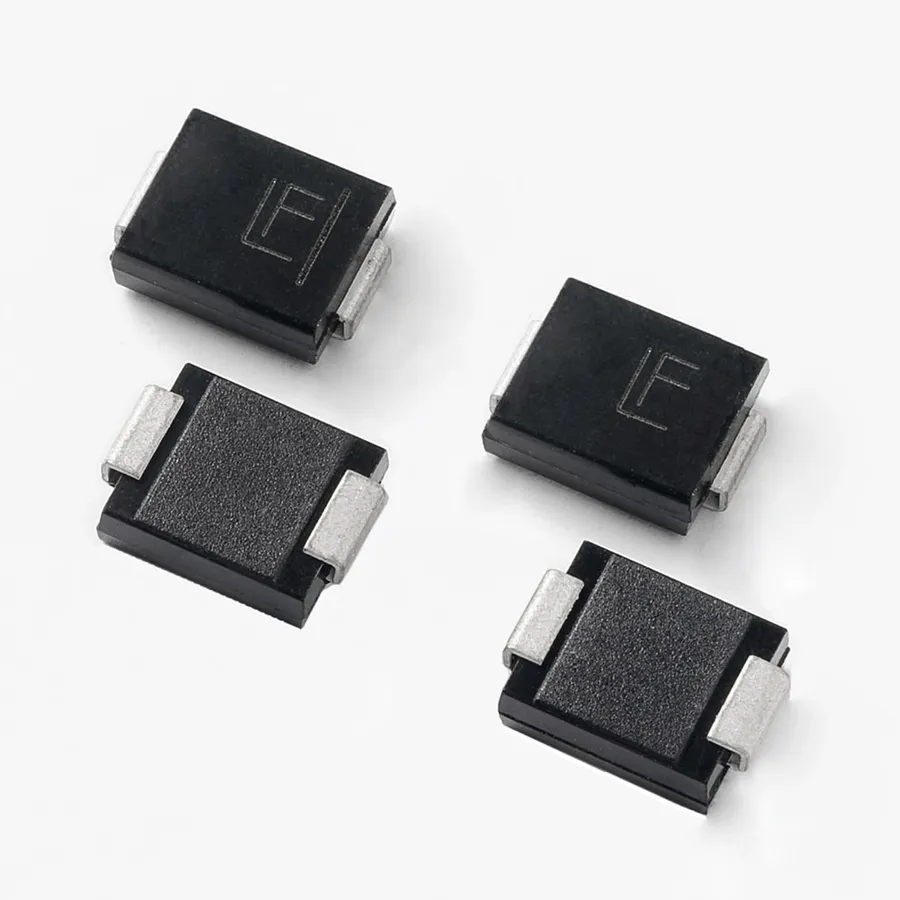
TVS diodes are indispensable components in modern electronics, serving as crucial protectors against transient voltage events that can damage sensitive circuits. Their applications span across diverse electronic systems, ensuring reliability and longevity by mitigating the effects of voltage surges, spikes, and electrostatic discharge (ESD).
Below are some prominent areas where TVS diodes are extensively used:
TVS (Transient Voltage Suppression) diodes and Zener diodes, while both diodes, serve distinct purposes in circuit protection and voltage regulation. TVS diodes are specifically engineered to protect sensitive electronics from transient voltage events like electrostatic discharge (ESD), lightning strikes, and inductive switching. Zener diodes, conversely, primarily function as voltage regulators or references, exhibiting different characteristics and response times to overvoltage scenarios.
| Feature | TVS Diode | Zener Diode |
|---|---|---|
| Primary Function | Transient voltage suppression (ESD, surges) | Voltage regulation, voltage reference |
| Response Time | Very fast (picoseconds) | Relatively slower (microseconds) |
| Overvoltage Behavior | Clamps voltage to a safe level, diverting excess current | Maintains a relatively constant voltage, can be damaged by high transient current |
| Power Handling | Designed for high peak pulse power | Limited power dissipation capability |
| Breakdown Voltage Tolerance | Wider tolerance, less precise | Tighter tolerance, more precise |
| Application Focus | Protection of sensitive electronics from transients | Voltage regulation in power supplies, signal conditioning |
| Failure Mode | Typically short-circuit | Can fail open or short |
The key distinction between TVS and Zener diodes lies in their intended application. TVS diodes are optimized for rapid response to transient events, using a clamping mechanism to divert surge current away from vulnerable components. Zener diodes, on the other hand, operate as shunt regulators, and are selected based on their reverse breakdown voltage, not their surge handling capability. Due to their slower response and power handling limitations, Zener diodes are unsuitable for transient suppression. Choosing between TVS and Zener diodes hinges on the circuit requirements; if the need is to protect against transient overvoltages, a TVS diode is the appropriate choice; for voltage regulation, the Zener diode is the more suitable option.
While both TVS (Transient Voltage Suppression) diodes and Schottky diodes are semiconductor devices, they serve fundamentally different purposes within electronic circuits. TVS diodes are designed to protect sensitive components from overvoltage events, whereas Schottky diodes are primarily used for their low forward voltage drop and fast switching speeds in applications like rectifiers and clamping circuits. Understanding these distinctions is crucial for selecting the appropriate diode for a given application.
| Feature | TVS Diode | Schottky Diode |
|---|---|---|
| Primary Function | Transient Voltage Suppression (Overvoltage Protection) | Rectification, Fast Switching |
| Operating Region | Reverse Bias (Breakdown Region) | Forward Bias |
| Forward Voltage Drop | High | Low |
| Response Time | Very Fast (Picoseconds) | Fast (Nanoseconds) |
| Current Handling | High Peak Pulse Current | Moderate Continuous Current |
| Capacitance | Higher | Lower |
| Typical Applications | Protection of sensitive circuits, ESD protection | Rectification, Switching Power Supplies, Clamping |
| Failure Mode | Typically short circuit failure | Typically open circuit failure |
In summary, TVS diodes are specialized protection devices optimized for handling high-energy transient events, while Schottky diodes are optimized for efficient current conduction and fast switching. They are not interchangeable and are chosen based on the specific functional needs of the circuit.
This section addresses common queries regarding TVS diode usage, focusing on practical aspects such as circuit placement, failure analysis, and testing protocols to guarantee effective device operation and system protection against transient voltage events.
Effective troubleshooting of TVS diodes is crucial to ensure the reliability of electronic circuits they protect. Testing these diodes involves verifying their ability to clamp overvoltage conditions and identifying potential failure modes. This section provides practical methods to perform these checks, ensuring proper operation.
Selecting the appropriate TVS diode is crucial for ensuring effective protection of electronic circuits against transient voltage events. This section provides a practical guide, focusing on key parameters and considerations to help engineers choose the optimal device for their specific application needs.
The selection process should follow a systematic approach, considering the following critical parameters:
In addition to these parameters, the following practical considerations are important:
By carefully evaluating these parameters and practical considerations, engineers can confidently select the right TVS diode to safeguard their circuits effectively against transient voltage threats, thus ensuring enhanced system reliability and longevity.
TVS diodes are indispensable components in modern electronics, providing crucial protection against transient voltage events. Their ability to quickly clamp and divert excess energy makes them essential for safeguarding sensitive circuitry and ensuring the reliability of electronic systems. Understanding the working principles, selection criteria, and application of TVS diodes empowers engineers and designers to build more robust and dependable electronic devices. As the demand for reliable and durable electronics continues to grow, the role of the TVS diode will remain vital in protecting our increasingly complex electronic world.

