Capacitors, essential components in modern electronics, store electrical energy. When these components are connected in series, their combined behavior differs significantly from individual capacitors, or capacitors in parallel. In series circuits, current flows through each capacitor sequentially, and the equivalent capacitance changes. This article will explain how capacitors in series work, and their applications.
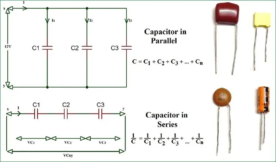
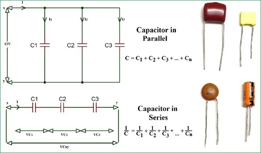
In a series configuration of capacitors, the fundamental principle is that all capacitors share the same charge, while the total voltage applied across the series circuit is distributed among the individual capacitors. This charge uniformity and voltage division are the defining characteristics of capacitors connected in series.
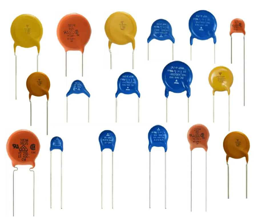
The total capacitance in a series circuit is not a straightforward sum of individual capacitor values; instead, it's calculated using the reciprocal of each capacitor's capacitance. This method results in a total capacitance (Ct) that is always less than the smallest individual capacitance within the series arrangement. Understanding this calculation is essential for accurately predicting circuit behavior.
The formula for calculating the total capacitance (Ct) of capacitors in series is given by:
\frac{1}{C_t} = \frac{1}{C_1} + \frac{1}{C_2} + \frac{1}{C_3} + \cdots + \frac{1}{C_n}
Where: - Ct is the total series capacitance. - C1, C2, C3,... Cn are the capacitance values of individual capacitors.
For example, if you have two capacitors in series, one with 10 microfarads (μF) and the other with 20 μF, the calculation is:
\frac{1}{C_t} = \frac{1}{10\mu F} + \frac{1}{20\mu F} = \frac{3}{20\mu F}
Therefore, the total capacitance (Ct) would be:
C_t = \frac{20\mu F}{3} \approx 6.67\mu F
As demonstrated above, the total capacitance of the series connection, 6.67μF, is indeed smaller than the smallest individual capacitance, which is 10μF. This underscores that the total capacitance in series is always less than the smallest capacitor's value.
| Number of Capacitors | Individual Capacitance Values | Total Capacitance (Ct) |
|---|---|---|
| 2 | C1 = 10μF, C2 = 20μF | 6.67 μF |
| 3 | C1 = 5μF, C2 = 10μF, C3 = 20μF | 2.86 μF |
| 2 | C1 = 1μF, C2 = 1μF | 0.5 μF |
In a series capacitor circuit, the total applied voltage is not uniformly distributed; rather, it is divided among the individual capacitors. This voltage division is inversely proportional to the capacitance of each capacitor. Understanding this principle is crucial for designing and analyzing circuits where multiple capacitors are connected in series.
The voltage drop across a specific capacitor within a series can be accurately calculated using the formula V_n = Q/C_n, where V_n is the voltage across the n-th capacitor, Q is the charge stored (which is constant across all capacitors in the series), and C_n is the capacitance of that specific capacitor. This formula highlights the direct relationship between voltage drop, stored charge, and capacitance.
| Parameter | Description |
|---|---|
| Voltage Drop (V_n) | The potential difference across a specific capacitor in the series. |
| Stored Charge (Q) | The electric charge accumulated in the capacitor, which remains the same for all capacitors in a series connection. |
| Capacitance (C_n) | The capacitance of the individual capacitor. |
In a series capacitor circuit, the current remains constant throughout all components. This implies that the rate of electron flow is uniform across every capacitor, a fundamental characteristic differentiating it from parallel capacitor configurations where current divides.
This consistent current flow stems from the fact that capacitors in series act like a single pathway for charge movement. Each capacitor contributes to the overall impedance of the circuit, but the same quantity of charge passes through each one in a given time interval.
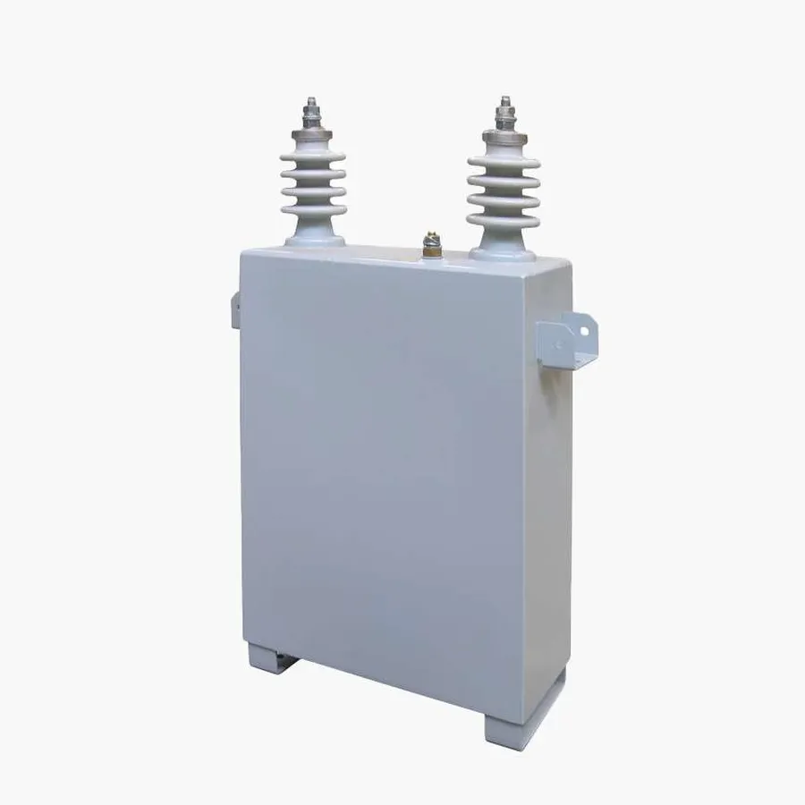
Connecting capacitors in series offers a strategic advantage, primarily enabling circuits to handle higher voltages than individual capacitors can withstand alone. This capability is critical in applications where the voltage demand exceeds the rating of commercially available single capacitor units, allowing engineers to achieve desired circuit functionality without compromising component integrity.
By distributing the total voltage across multiple series capacitors, the voltage across each capacitor is reduced, allowing the use of components with lower individual voltage ratings. This approach is crucial in high-voltage applications, preventing damage to capacitors and ensuring long-term reliability. It is important to note that this is achieved with an associated trade off, that is the total capacitance of the circuit will be reduced when connecting capacitors in series.
Connecting capacitors in series offers a method to manage voltage requirements in a circuit, specifically allowing a circuit to withstand higher voltages than individual components are rated for. However, this configuration comes at the cost of reduced overall capacitance. This trade-off impacts the amount of energy that can be stored by the circuit, which is less than the sum of individual capacitor's energy storage or when connected in parallel. The advantages and disadvantages are summarized in the table below.
| Feature | Advantages | Disadvantages |
|---|---|---|
| Voltage Handling | Increases the overall voltage rating of the circuit, enabling operation in higher voltage environments. | None specific to voltage but capacitance is reduced. |
| Capacitance | None directly. Allows for creating non-standard capacitance values. | Reduces the total capacitance. Total capacitance is lower than the smallest capacitor in the series. |
| Energy Storage | None directly. Allows for creating non-standard capacitance values, which can affect energy storage, when paired with voltage. | Reduces the overall energy storage capacity of the circuit. |
| Applications | Suitable for high-voltage applications where voltage rating is a primary concern. | Not optimal for applications where high capacitance or energy storage is crucial. |
This section addresses common questions about capacitors connected in series, clarifying their behavior and characteristics within electrical circuits. Understanding these fundamental concepts is crucial for effective circuit design and troubleshooting.
Capacitors in series are strategically employed in scenarios demanding high voltage handling, primarily in voltage multiplier circuits and smoothing circuits, where the trade-off between increased voltage tolerance and decreased overall capacitance is advantageous. These applications often involve voltage levels that exceed the rating of individual capacitors, necessitating the series configuration.
While the reduction in total capacitance is a drawback, the need for high voltage handling justifies the usage of series capacitors in these specialized contexts. Proper design ensures that voltage distribution is managed effectively.
Working with series capacitors requires careful consideration of voltage ratings, capacitance values, and safety procedures, especially in high-voltage applications. Proper implementation is crucial to ensure the circuit performs as designed and to avoid potential hazards.
In conclusion, capacitors in series behave differently than in parallel or individually. The key takeaway is that series connection reduces the overall capacitance, but they also enable higher voltage ratings. Understanding these characteristics is essential for designing and troubleshooting electronic circuits. This method is effective when dealing with high-voltage requirements, and the capacitor series configuration is frequently used in many applications.

