In our interconnected world, electronic circuits are the backbone of countless devices, from smartphones to advanced medical equipment. At the heart of these circuits are components like the circuit resistor, acting as the unsung hero, controlling electrical flow, just like a valve regulates water pressure in pipes. This article will delve deep into understanding circuit resistors – their purpose, types, applications, and more, demystifying these crucial components.
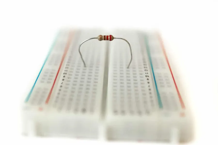
A circuit resistor is a fundamental passive electrical component engineered to oppose the flow of electrical current within a circuit. This opposition, known as resistance, is quantified in ohms (Ω) and is crucial for controlling current levels, attenuating voltage, and ensuring proper circuit operation. Resistors achieve this by converting electrical energy into heat, a process known as Joule heating.
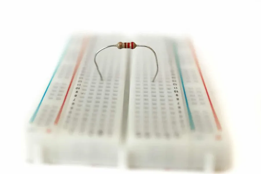
At the core of every circuit resistor lies the fundamental principle of electrical resistance, which is the opposition to the flow of electric current. This opposition, measured in ohms (Ω), is not merely an obstruction but a crucial property that allows us to manipulate and control electrical circuits. The behavior of a resistor is elegantly described by Ohm's Law, V = IR, which states that the voltage (V) across a resistor is directly proportional to the current (I) flowing through it and the resistance (R) of the resistor.
Understanding how resistance affects current is vital for circuit design. A higher resistance will result in a lower current for a given voltage, and vice versa. This capability to control current makes resistors indispensable for numerous electronic applications. When a voltage is applied across a resistor, the electrical energy is converted into heat due to collisions between charge carriers and the material of the resistor, this is called the Joule effect, the effect is especially apparent when the electrical current and resistance are high. The heat that generated dissipates into the environment.
| Concept | Description | Units |
|---|---|---|
| Resistance (R) | The opposition to current flow. | Ohms (Ω) |
| Current (I) | The flow of electrical charge. | Amperes (A) |
| Voltage (V) | The electrical potential difference. | Volts (V) |
| Ohm's Law | V = IR, voltage equals current times resistance | N/A |
The relationship between voltage, current and resistance is fundamental to understanding circuit behavior. The resistance of a resistor depends on several factors such as its material, length and cross-sectional area. Materials that have high resistance, are called insulators, materials with low resistance are called conductors, and resistors are specifically designed to exhibit a controlled amount of resistance between these two extremes. In essence, the resistor is a fundamental control device in an electronic circuit.
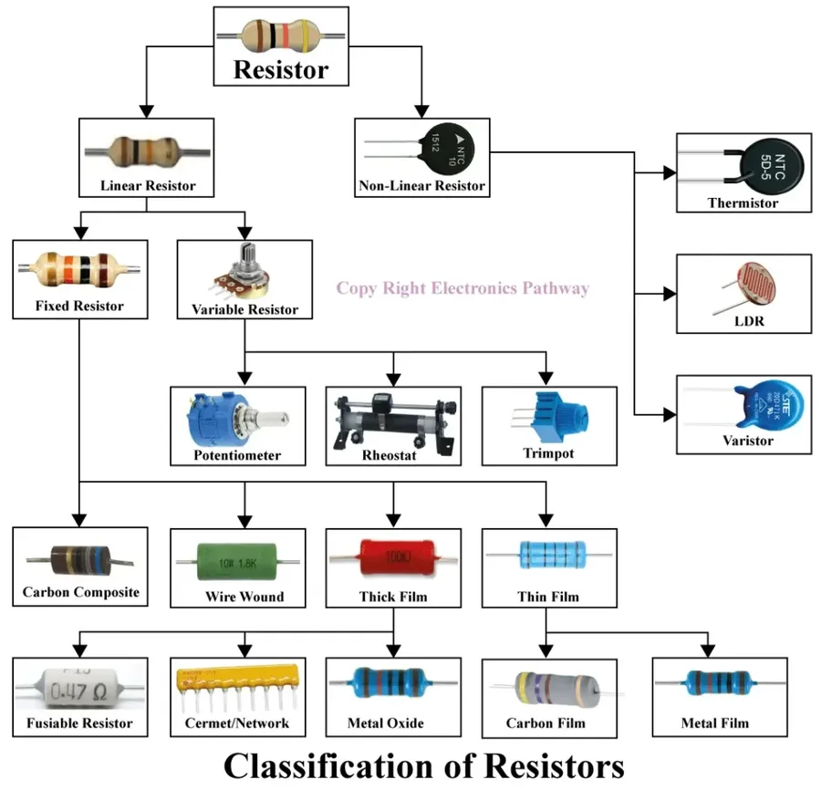
Circuit resistors are diverse components, each designed with unique characteristics to meet specific application needs. These can be broadly categorized into fixed resistors, variable resistors, and specialized resistors, each offering distinct functionalities in electronic circuits.
| Resistor Type | Description | Typical Applications | Advantages | Disadvantages |
|---|---|---|---|---|
| Fixed Resistors | Provide a constant resistance value that is set during manufacturing. | General circuits, current limiting, voltage division. | Low cost, widely available, reliable. | Resistance value cannot be changed, less precise. |
| Carbon Film | A thin carbon film is deposited on a ceramic substrate. | General-purpose circuits. | Inexpensive, good for general use. | High temperature sensitivity, less precise than metal film. |
| Metal Film | Thin metal film deposited on a ceramic substrate. | Precision circuits, high-accuracy applications. | High precision, low temperature coefficient, low noise. | More expensive than carbon film resistors. |
| Wire-Wound | Made by winding a resistance wire around an insulating core. | High-power applications, precision circuits. | High power handling capability, high precision. | Inductive, higher cost, larger size. |
| Variable Resistors | Allow for the adjustment of resistance. | Adjustable circuits, volume controls, tuning. | Adjustable resistance value. | Less stable than fixed resistors, potential for mechanical wear. |
| Potentiometers | Three terminals and a rotating or sliding contact. | Voltage division, user-adjustable settings. | Versatile for voltage control. | Limited power rating, less precise. |
| Rheostats | Two terminals and a sliding contact. | Current control, motor speed adjustments. | Can handle higher currents than potentiometers. | Limited variability, may not be as precise. |
| Specialized Resistors | Have specific properties based on environmental conditions. | Temperature or light-sensitive circuits. | Respond to specific environmental factors. | Performance is tied to the specific parameter they respond to. |
| Thermistors | Resistance changes with temperature. | Temperature sensing, thermal compensation. | High temperature sensitivity. | Non-linear response, limited temperature range. |
| Photoresistors | Resistance changes with light intensity. | Light sensing, automated lighting control. | High sensitivity to light. | Response time may be slow, not highly stable. |
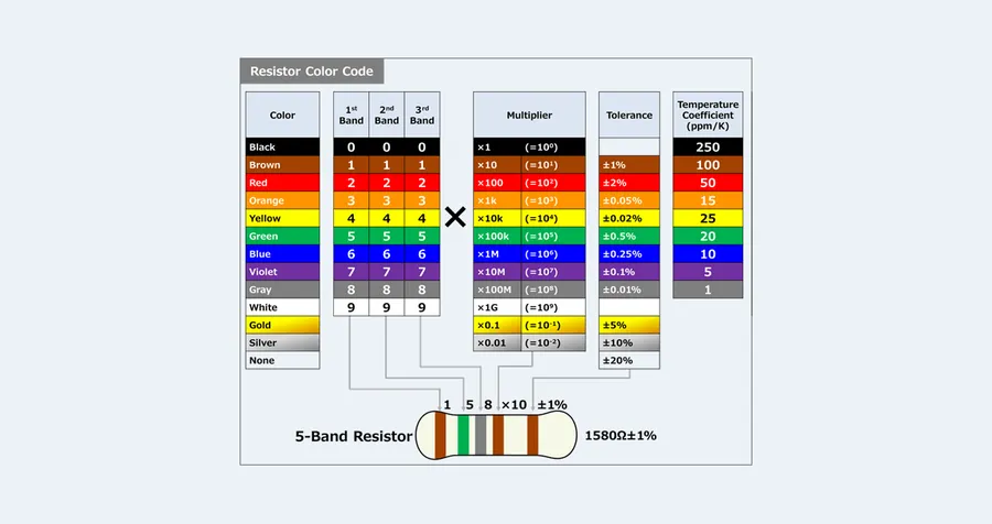
Resistor color codes and markings provide a standardized method for indicating the resistance value and tolerance of a resistor. Understanding these codes is essential for accurately identifying and using resistors in circuit design and repair. These markings use a system of colored bands or alphanumeric codes, allowing for quick and efficient identification of resistor specifications.
| Band | Color | Digit Value | Multiplier | Tolerance |
|---|---|---|---|---|
| 1st Band | Black | 0 | N/A | N/A |
| 1st Band | Brown | 1 | 10^1 | ±1% |
| 1st Band | Red | 2 | 10^2 | ±2% |
| 1st Band | Orange | 3 | 10^3 | N/A |
| 1st Band | Yellow | 4 | 10^4 | N/A |
| 1st Band | Green | 5 | 10^5 | ±0.5% |
| 1st Band | Blue | 6 | 10^6 | ±0.25% |
| 1st Band | Violet | 7 | 10^7 | ±0.1% |
| 1st Band | Grey | 8 | 10^8 | ±0.05% |
| 1st Band | White | 9 | N/A | N/A |
| Multiplier | Gold | N/A | 10^-1 | ±5% |
| Multiplier | Silver | N/A | 10^-2 | ±10% |
| Tolerance | None | N/A | N/A | ±20% |
For a typical 4-band resistor, the first two bands represent the first two digits of the resistance value, the third band is the multiplier, and the fourth is the tolerance. A 5-band resistor adds a third significant digit, increasing precision. Some resistors also include a sixth band to indicate temperature coefficient.
Understanding how to decode these color bands correctly is crucial for selecting the right resistor for a specific application, avoiding any misinterpretations that could lead to circuit malfunctions or damage. Always double check your readings and refer to reliable resources when interpreting resistor values.
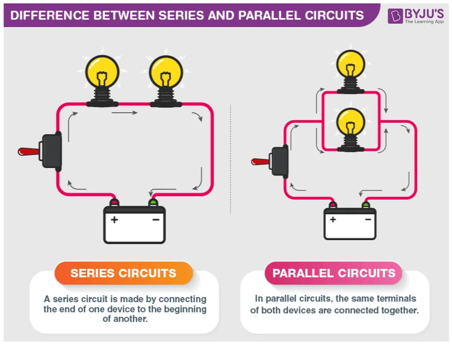
Understanding how resistors behave in series and parallel configurations is fundamental to circuit analysis and design. The arrangement of resistors significantly impacts the overall resistance and current flow within a circuit, requiring distinct calculation methods for each configuration.
| Characteristic | Series Circuits | Parallel Circuits |
|---|---|---|
| Current Flow | Same through all resistors | Divides among branches |
| Voltage | Divides across resistors | Same across all resistors |
| Total Resistance (RT) | RT = R1 + R2 + R3 + ... | 1/RT = 1/R1 + 1/R2 + 1/R3 + ... |
| Calculation | Simple addition of resistance values. | Reciprocal of the sum of reciprocals of resistance values. |
In series circuits, resistors are connected end-to-end, forming a single path for current flow. The total resistance is simply the sum of individual resistances. Conversely, in parallel circuits, resistors are connected side-by-side, providing multiple paths for current. The total resistance in parallel is always less than the smallest individual resistance and requires a different formula calculation.
These configurations are crucial in circuit design as they allow engineers to manipulate current and voltage levels, tailoring the circuit to meet specific application needs. For instance, resistors in series can be used to limit current, while resistors in parallel can be used to divide current among different paths.
Diagrammatically, a series circuit shows components connected one after another along a single line, while a parallel circuit demonstrates components with their ends connected to the same nodes, creating branches.
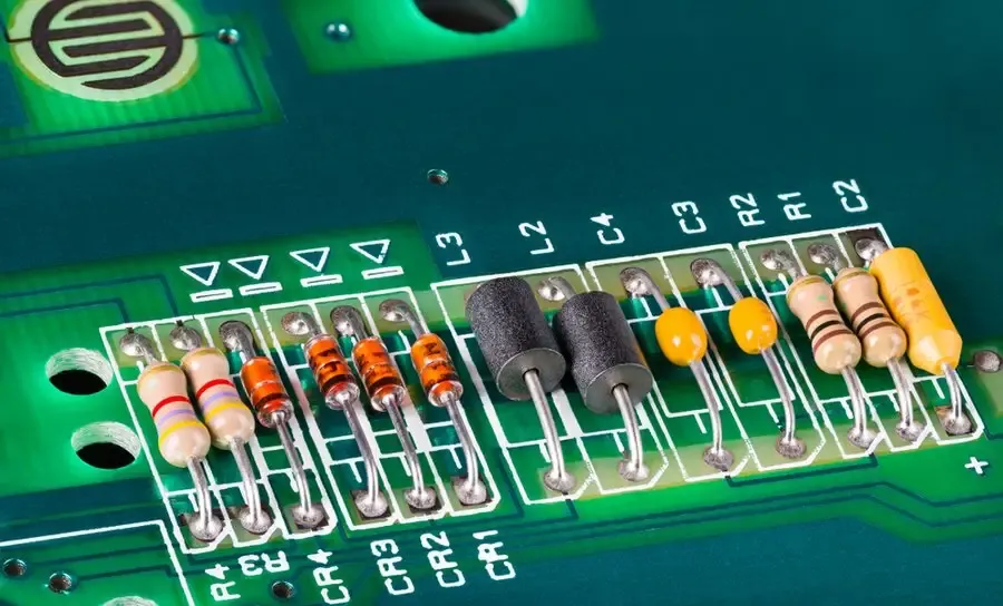
Circuit resistors are ubiquitous in electronics, performing essential functions that ensure proper operation and protection of various circuits. They are not merely passive components, but rather active elements in controlling current, voltage, and signal integrity. Their widespread use stems from their ability to precisely manage electrical parameters, which is crucial for the stability and reliability of electronic systems. This section will explore key applications of resistors in real-world scenarios, supported by specific examples.
Resistors are pivotal in several key applications, broadly categorized as current limiting, voltage division, signal biasing, and impedance matching. These applications showcase how resistors actively shape the behavior of electrical circuits to achieve the desired functionalities. Each use case emphasizes different aspects of resistive behavior and its importance.
| Application | Function | Example Scenario |
|---|---|---|
| Current Limiting | Protect sensitive components by limiting current flow | LED circuit with a series resistor |
| Voltage Division | Generate a specific fraction of the input voltage | Voltage divider in a sensor circuit |
| Signal Biasing | Establish desired operating points for transistors | Transistor amplifier with bias resistors |
| Impedance Matching | Maximize power transfer and reduce signal loss | RF amplifier with matching network |
In summary, resistors are not just simple components but are critical elements that enable control and manipulation of electrical signals within a vast array of electronic applications. These examples highlight the essential role of resistors in ensuring the reliability and performance of electronic circuits.
This section addresses common questions about circuit resistors, providing practical answers and insights to enhance understanding for beginners and hobbyists.
Effective troubleshooting of circuit resistors involves diagnosing common issues such as overheating, failures caused by overload, and physical damage. Understanding these failure modes and implementing proper testing techniques are essential for maintaining circuit integrity and reliability.
| Symptom | Possible Cause | Troubleshooting Step |
|---|---|---|
| Discoloration or Charring | Overheating due to excessive power dissipation | Check the resistor's power rating and calculate power in the circuit |
| Open circuit (infinite resistance) | Extreme overheating or physical damage | Measure resistance with a multimeter; if open, replace resistor |
| Incorrect resistance value | Value drift, or physical damage | Measure resistance, compare to color codes and markings; replace if outside tolerance |
| Physical cracks or breaks | Physical stress | Replace damaged resistors |
| Intermittent or poor connection | Poor solder joint | Inspect solder joint, reflow and check continuity |
In summary, circuit resistors are fundamental elements in electronic circuits, playing vital roles in managing current flow and enabling various functionalities. Understanding their types, applications, and how they interact within circuits is key to successful electronic design and troubleshooting. As technology evolves, so will the designs and applications of resistors, highlighting their enduring importance in the field of electronics. The ability to control resistance remains a cornerstone of modern electrical engineering and will continue to be important in future innovations.

