In the dynamic world of electronics, the humble LED, or Light Emitting Diode, shines brightly in countless applications. Yet, this small marvel cannot work alone. Like a seasoned athlete needs a coach, an LED needs a resistor to regulate its current flow, preventing burnout and ensuring a long life. This article will illuminate the vital role of resistor led pairings in circuits, providing a comprehensive understanding of their selection, placement, and impact on LED performance. Through examples from both everyday use and complex electronic applications, we'll delve into the practical aspects of incorporating resistors with LEDs, bridging the gap between theory and practice.
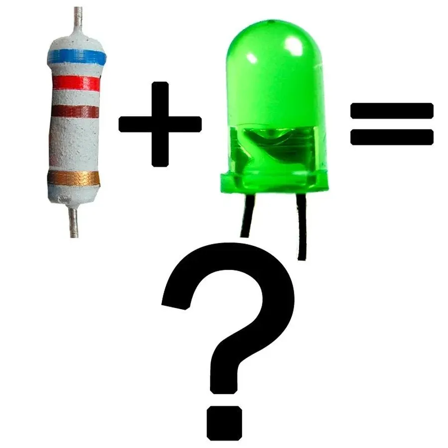
Light Emitting Diodes (LEDs), unlike incandescent bulbs, are current-driven devices; they require a specific amount of electrical current to operate correctly. Directly connecting an LED to a voltage source without a current-limiting mechanism, such as a resistor, can lead to excessive current flow. This overcurrent causes overheating, potentially leading to immediate failure or a significantly shortened lifespan. Resistors are therefore essential for managing the current and ensuring the LED operates safely and within its specifications.
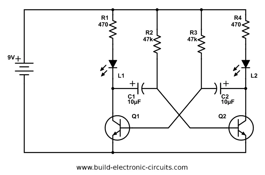
Determining the appropriate resistor value for an LED is crucial for its longevity and optimal performance. This calculation hinges on understanding Ohm's Law and applying it to the specific characteristics of the LED and the power source. By limiting current flow, a resistor prevents damage to the LED and ensures it operates within its specified parameters.
Ohm's Law, expressed as V = IR (Voltage = Current * Resistance), is the foundation for calculating the required resistor value. When using an LED, you must consider the voltage drop across the LED (forward voltage) and the desired current flow (forward current) to calculate the series resistance. The formula is R = (Vs - Vf) / If. Where R is resistance, Vs is supply voltage, Vf is forward voltage and If is forward current.
| Parameter | Description | Units |
|---|---|---|
| Vs (Supply Voltage) | The voltage provided by the power source. | Volts (V) |
| Vf (Forward Voltage) | The voltage drop across the LED when it's conducting. | Volts (V) |
| If (Forward Current) | The desired current flowing through the LED for optimal brightness and lifespan. | Amperes (A) or Milliamperes (mA) |
| R (Resistance) | The required resistance to limit current through the LED | Ohms (Ω) |
Let's consider a typical example. Suppose you have a 5V power supply (Vs), an LED with a forward voltage of 2V (Vf), and a desired forward current of 20mA (0.02A). The resistor value would be calculated as follows: R = (5V - 2V) / 0.02A = 150Ω. Therefore, a 150 ohm resistor should be used for this scenario. If the result is not a standard value, it's typical to use the next highest standard resistor value.
It is also important to consider the power rating of the resistor, which must be able to handle the power dissipation without overheating. The power dissipated by the resistor can be found using P = I^2 * R. For the example above it would be P = (0.02A)^2 * 150 = 0.06W . Typically a 1/4 watt (0.25W) resistor would be sufficient in this situation.
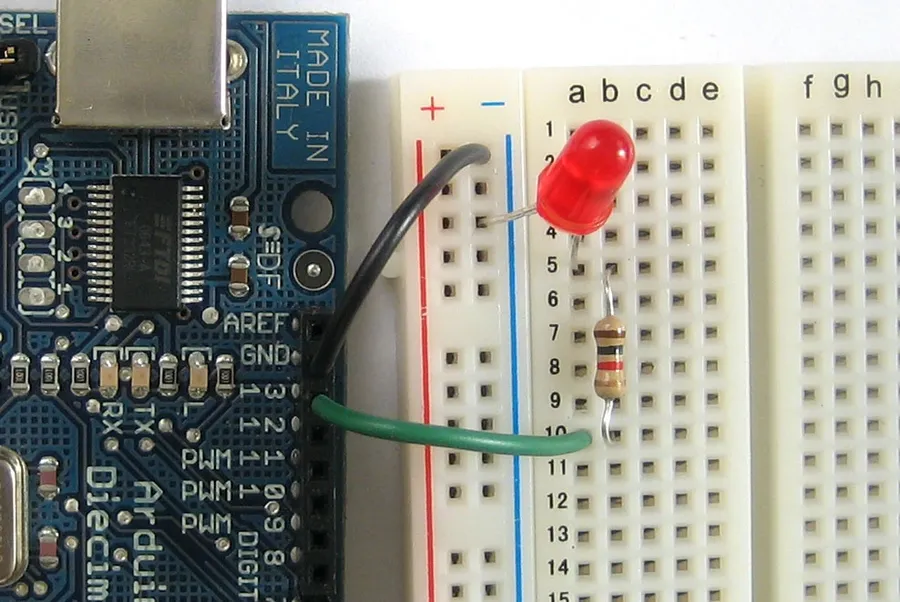
Calculating the correct resistor value for a 5V LED is a straightforward process when using Ohm's Law. This step-by-step guide simplifies the calculation, enabling users to safely and effectively implement LEDs in their projects. The primary goal is to limit the current flowing through the LED to prevent damage, ensuring it operates within its rated parameters.
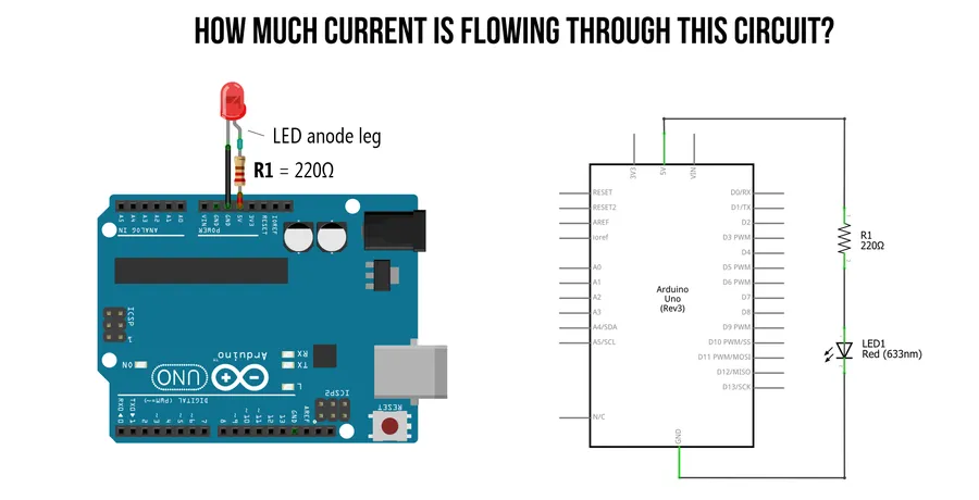
In a series circuit containing an LED and a resistor, the placement of the resistor—whether before or after the LED—does not affect the circuit's functionality in terms of current limiting. The current flowing through each component is the same within a series circuit, thus, the resistor limits the current regardless of its position.
This principle stems from the fundamental laws of electrical circuits. In a series configuration, the total resistance is the sum of individual resistances. Therefore, the current flowing through each component is identical. Consequently, the current-limiting function of the resistor remains consistent irrespective of its placement relative to the LED.
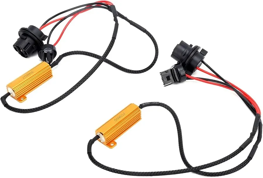
Load resistors play a crucial role when replacing traditional incandescent bulbs with LEDs, particularly in automotive applications. These resistors address the issue of hyperflashing or error messages by mimicking the electrical load of the original bulb. The reduced current draw of LEDs can confuse vehicle's onboard systems, requiring load resistors to simulate the higher current demand of incandescent bulbs and ensure proper functionality.
When retrofitting LEDs into applications designed for incandescent lights, the significant reduction in current draw by the LED can create problems for the system. For instance, modern cars often monitor the current draw of their turn signal circuits to detect burnt out bulbs. Because an LED draws far less current than a traditional incandescent, the vehicle's system may register this as a faulty bulb, resulting in a faster flashing (hyperflashing) signal or an error message on the dashboard. A load resistor is placed in parallel to the LED, causing an additional electrical load and mimicking the current consumption of a regular bulb.
| Problem | Cause | Solution |
|---|---|---|
| Hyperflashing Turn Signals | LEDs draw less current than incandescent bulbs, causing the flasher relay to operate too quickly. | Add a load resistor in parallel with the LED. |
| Dashboard Error Message | The vehicle's system detects the low current draw and thinks the bulb is out. | Add a load resistor in parallel with the LED. |
It's crucial to calculate the correct wattage for the load resistor. A resistor with an insufficient power rating may overheat and fail. The power (P) dissipated by the resistor can be calculated using the formula: P = I² * R, where 'I' is the current flowing through the resistor and 'R' is the resistance value. Selecting a load resistor with a wattage rating significantly higher than the calculated power is recommended for safety and reliability.
Although load resistors effectively solve the compatibility issues, they also introduce an inefficiency; the power used by the resistor is converted to heat. This heat must be managed properly to avoid any damage. Because of this, choosing a high quality resistor designed for this purpose is paramount.
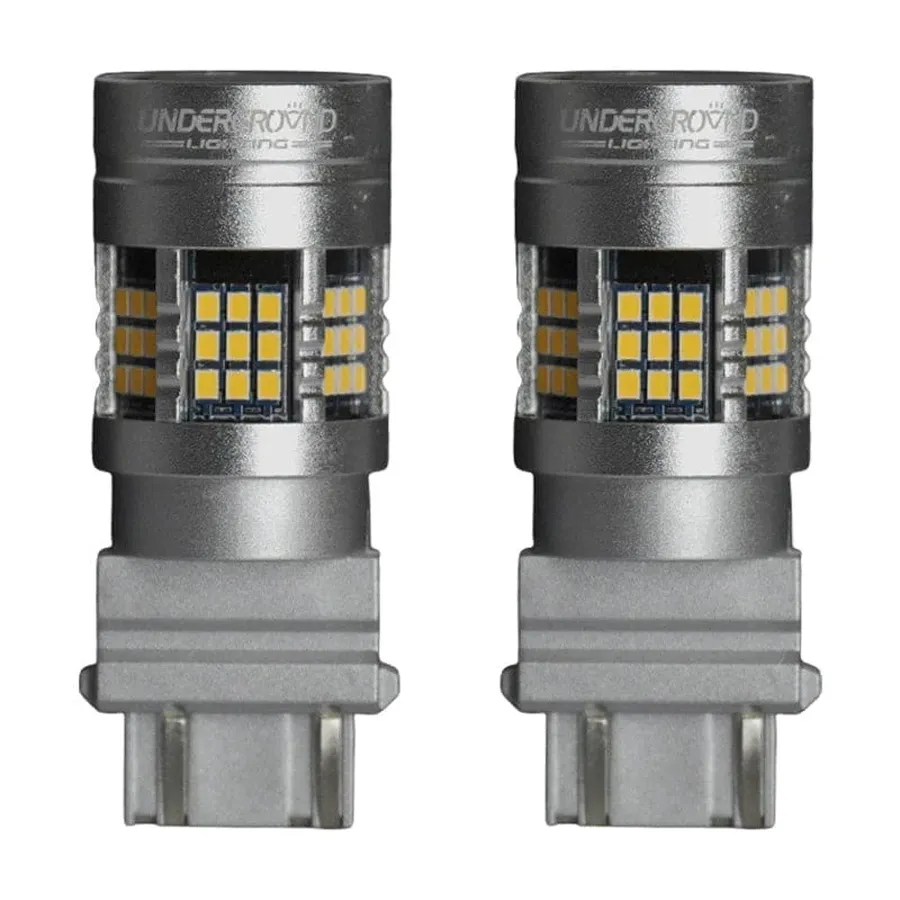
Certain LEDs are manufactured with an integrated resistor, offering a convenient solution that simplifies circuit design by eliminating the need for external components. These 'resistor LEDs' are particularly useful in applications where space is limited or for users seeking plug-and-play simplicity. While offering ease of use, these integrated solutions have specific benefits and limitations that must be considered.
The primary advantage of using LEDs with built-in resistors is the ease of implementation. By incorporating the current-limiting resistor within the LED package, the need for manual calculation and external soldering of a resistor is removed. This not only saves time but also reduces the possibility of errors associated with selecting the incorrect resistor value. Furthermore, these LEDs often come with a standardized voltage and current rating, which makes them user-friendly, especially for beginners.
Despite the benefits, there are limitations to LEDs with built-in resistors. The main drawback is reduced flexibility. The integrated resistor is typically designed for a specific voltage, and if the supply voltage differs, the LED might not operate at its optimal brightness or could potentially be damaged. Additionally, the fixed resistance value limits the ability to adjust the brightness of the LED to suit specific application requirements. Moreover, if the built-in resistor fails, the entire LED unit needs replacement rather than just the resistor.
| Feature | LED with Built-in Resistor | LED with External Resistor |
|---|---|---|
| Complexity | Simplified, no external resistor needed | Requires manual calculation and external resistor |
| Flexibility | Limited, fixed voltage and current | High, can customize for voltage and brightness |
| Space | Compact, integrates resistor | Requires more space for external components |
| Cost | Potentially higher upfront cost | Lower cost per component |
| Replacement | Requires replacing entire LED unit if resistor fails | Replace only the resistor if it fails |
The brightness of an LED is directly proportional to the current flowing through it; therefore, manipulating the resistor value in series with the LED provides a straightforward means of adjusting its brightness. A higher resistance restricts current flow, resulting in a dimmer LED, while a lower resistance allows more current, leading to a brighter output. Understanding this relationship is crucial for fine-tuning the visual output of LED-based projects.
| Resistor Value | Current Flow | LED Brightness |
|---|---|---|
| High | Low | Dim |
| Low | High | Bright |
It's essential to operate within the LED's specified current range. While a lower resistor can increase brightness, exceeding the maximum forward current of the LED can lead to premature failure or complete burnout. Conversely, choosing a resistor value that results in very low current might make the LED too dim to be practically useful. Therefore, resistor selection should be a balance between desired brightness and the LED’s specifications.
For example, consider a situation where a 5V power supply is used with a 2.0V, 20mA LED. Using a resistor that is calculated for that current will produce a certain brightness. Using a higher resistor such as twice the original value will lead to a dimmer light, while using half the resistance would lead to double the current and hence a much brighter LED - this is assuming that this value is within the LED's maximum specifications.
This section addresses common queries regarding the use of resistors with LEDs, providing clear and concise answers to ensure a solid understanding of their critical role in LED circuit design.
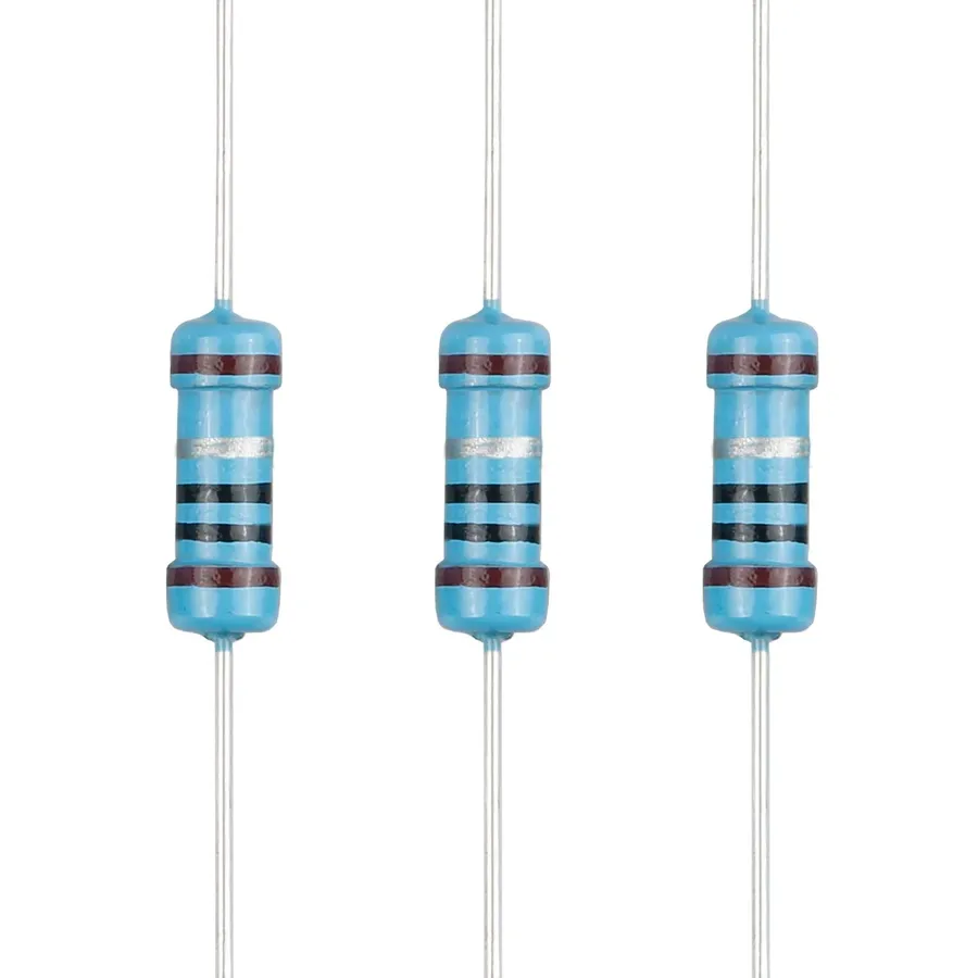
Selecting the appropriate wattage rating for a resistor in an LED circuit is crucial to prevent overheating and ensure reliable operation. The resistor must be able to safely dissipate the power generated without exceeding its limits, which can lead to failure or even fire hazards. This section provides guidance on calculating and selecting the right wattage for your LED resistor.
The key to choosing the correct resistor wattage is understanding the power it will need to dissipate. Power (P) is measured in watts and can be calculated using the following formulas:
P = I^2 * R
Where: * P is power in watts (W) * I is the current flowing through the resistor in amperes (A) * R is the resistance in ohms (Ω)
Alternatively, if you know the voltage drop across the resistor (V_resistor) and the current flowing through it, you can use:
P = V_{resistor} * I
Where: * P is power in watts (W) * V_resistor is the voltage drop across the resistor in volts (V) * I is the current flowing through the resistor in amperes (A)
To determine the power dissipated by the resistor, we must first calculate the current (I) flowing through it. Using Ohm's Law (I = V/R), and the values calculated in the previous sections. Once the current is determined, use the above formulas to calculate the power dissipated by the resistor.
Once you have calculated the power dissipation, select a resistor with a wattage rating that is significantly higher than the calculated value. It is a standard practice to choose a resistor with at least twice the calculated power dissipation. This provides a safety margin and allows for fluctuations in current or environmental conditions. For example, if the calculated power dissipation is 0.1 watts, choose a resistor rated for at least 0.25 watts or higher.
Standard resistor wattage ratings include: 1/8W, 1/4W, 1/2W, 1W, 2W, etc. Opt for higher wattage ratings if you are unsure or dealing with critical applications.
In conclusion, the resistor plays a critical role in any LED circuit. Understanding how to calculate the correct resistor led combination, and how to incorporate built-in or load resistors, is essential for ensuring the longevity and optimal performance of LEDs. As technology advances, the importance of proper current regulation remains paramount, highlighting the enduring significance of this humble component in countless applications, from simple indicators to complex lighting systems. By mastering these concepts, you’re equipped to confidently navigate the world of LED circuits and maximize their potential.

