From the ubiquitous smartphone in your pocket to the complex machinery powering factories, the unassuming 1uF capacitor plays a critical role. This small component, often no bigger than a grain of rice, is essential for storing and releasing electrical energy. This article will demystify the 1uF capacitor, exploring its various types, uses, and how to select the correct one for your project.
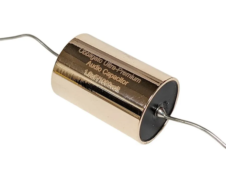
A 1uF capacitor is a fundamental electronic component designed to store electrical energy in an electric field. The unit '1uF' denotes its capacitance, which is specifically one microfarad. Capacitance quantifies the amount of charge a capacitor can store for a given voltage. This component is a cornerstone in countless electronic circuits, performing various essential functions based on this ability to store charge.
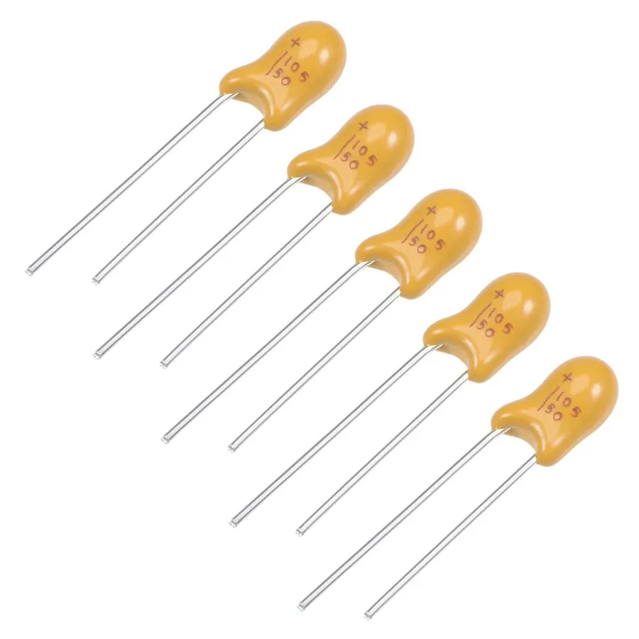
1uF capacitors are not monolithic; they are manufactured using various materials and construction techniques, leading to diverse performance characteristics and suitability for different applications. The most common types include ceramic, electrolytic, film, and SMD (Surface Mount Device) capacitors. Each type offers unique advantages and disadvantages in terms of size, cost, stability, and operating frequency.
| Capacitor Type | Key Characteristics | Pros | Cons | Typical Applications |
|---|---|---|---|---|
| Ceramic | Non-polarized, low cost, small size, available in various temperature coefficients | Low cost, small size, good high-frequency performance | Lower capacitance values, capacitance varies with temperature and voltage | General-purpose applications, decoupling, high-frequency circuits |
| Electrolytic | Polarized, high capacitance values, higher ESR, higher tolerance | High capacitance in a small package | Polarized, higher ESR (Equivalent Series Resistance), limited frequency response, shorter lifespan compared to other types | Power supply filtering, decoupling, low-frequency applications |
| Film | Non-polarized, high precision, stable, low tolerance, good high-frequency performance | High stability and precision, low tolerance, good high-frequency performance, lower ESR | Larger size compared to other types, higher cost | High-end audio, timing circuits, precision analog circuits |
| SMD | Available in ceramic, electrolytic, and film types, designed for surface mounting | Small size, suitable for automated assembly | Can be difficult to solder manually, can be fragile during rework | High-density PCBs, miniaturized electronics |
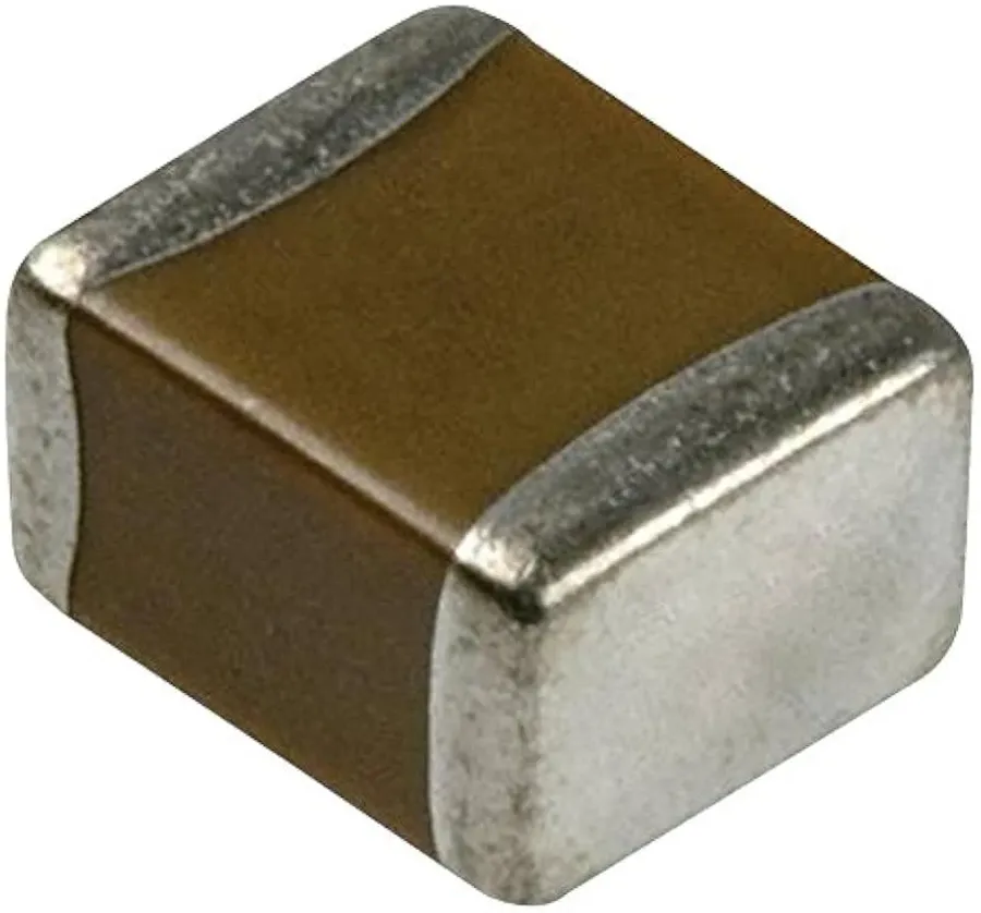
Ceramic 1uF capacitors are ubiquitous in electronics due to their advantageous combination of low cost, compact size, and excellent performance in high-frequency circuits. These capacitors utilize ceramic materials as the dielectric, enabling efficient energy storage and discharge capabilities suitable for a wide array of applications.
| Characteristic | Description |
|---|---|
| Dielectric Material | Ceramic (e.g., barium titanate, calcium zirconate) |
| Capacitance Value | 1 microfarad (1uF) |
| Tolerance | Varies, typically ±5%, ±10%, or ±20% |
| Temperature Coefficient | Varies depending on the dielectric type, can be positive, negative, or stable |
| Voltage Rating | Ranges from a few volts to kilovolts, depending on size and dielectric material |
| ESR | Low Equivalent Series Resistance, suitable for high frequency applications |
| Size | Small and compact, available in various SMD and through-hole packages |
| Cost | Relatively inexpensive compared to other capacitor types |
The compact size of ceramic 1uF capacitors makes them ideal for use in densely populated circuit boards, while their low equivalent series resistance (ESR) allows them to operate effectively in high-frequency applications such as filtering, bypassing, and signal coupling. These characteristics contribute to their widespread use in a variety of electronic devices. They are often chosen for decoupling power supply lines to integrated circuits, thereby minimizing noise and ensuring stable operation.
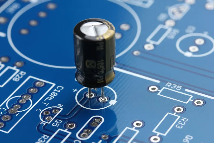
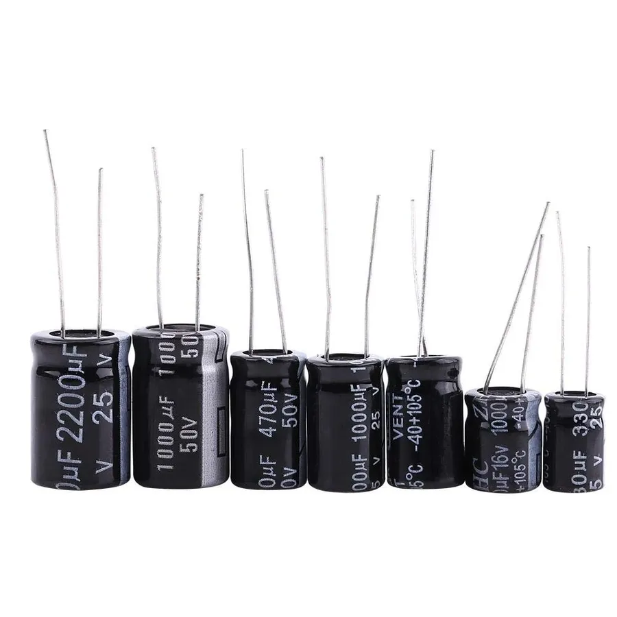
Electrolytic 1uF capacitors are characterized by their high capacitance-to-volume ratio, making them suitable for applications requiring significant charge storage within a compact size. However, their inherent properties, including polarity, equivalent series resistance (ESR), and tolerance limitations, necessitate careful consideration in their application. Understanding these characteristics is crucial for effective circuit design.
When using electrolytic 1uF capacitors, consider these key parameters:
The following table summarizes the use cases for electrolytic 1uF capacitors:
| Use Case | Advantages | Disadvantages |
|---|---|---|
| Power supply filtering | High capacitance for smoothing voltage ripples, relatively inexpensive. | Higher ESR compared to other capacitor types may limit high-frequency performance. Polarity is a limitation for some applications. |
| Decoupling | Can be used for decoupling in low-frequency circuits where its high capacitance is advantageous, cost-effective for bulk capacitance. | Higher ESR can limit effectiveness in high-frequency decoupling. Polarity is still a consideration. |
| Timing circuits | Used in some basic timing circuits. | Tolerance and ESR may lead to unpredictable timing characteristics, not suitable for precision timing applications. |
When to avoid using Electrolytic 1uF capacitors:
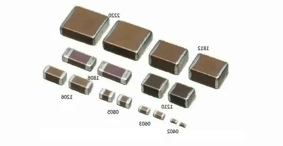
Surface Mount Device (SMD) 1uF capacitors are integral components in modern electronics, particularly for high-density printed circuit board (PCB) designs. Their compact form factor and compatibility with automated assembly processes make them a staple in miniaturized electronic devices. This section details the advantages and practical considerations associated with their implementation.
| Feature | SMD 1uF Capacitor | Leaded 1uF Capacitor |
|---|---|---|
| Size | Extremely small, various standardized case sizes (e.g., 0603, 0805) | Larger, with leads for through-hole mounting |
| Assembly | Automated pick-and-place, reflow soldering | Manual or automated through-hole mounting, wave soldering |
| Density | High component density possible on PCB | Lower component density due to larger size and lead spacing |
| Parasitic Inductance | Lower parasitic inductance due to shorter lead lengths | Higher parasitic inductance due to longer lead lengths |
| Cost | Typically lower in high volume due to automation | May be higher in high volume due to additional processing and materials |
| Suitability | Ideal for high-frequency and miniaturized applications | Better for prototyping and through-hole designs |
The most common types of SMD 1uF capacitors are multilayer ceramic capacitors (MLCCs), tantalum capacitors, and film capacitors. MLCCs are the most prevalent due to their low cost, small size, and excellent high-frequency performance. Tantalum capacitors offer higher capacitance per volume but are more expensive and polarity-sensitive. Film capacitors provide higher precision and stability but are typically larger.
Deciphering the codes and markings on 1uF capacitors is crucial for accurate identification and proper circuit integration. These markings indicate critical parameters like capacitance, tolerance, voltage rating, and temperature coefficient, and vary depending on the capacitor type and manufacturer.
Understanding these codes prevents errors in circuit design and ensures optimal performance, using the wrong component can severely impact circuit operation. Different capacitor types have varied coding systems; for example, ceramic capacitors frequently utilize a three-digit or four-digit numerical code system supplemented by letter codes, while electrolytic capacitors typically use explicit markings for capacitance and voltage ratings, and SMD capacitors use a compact alphanumeric coding system.
| Marking Type | Description | Example | Implication |
|---|---|---|---|
| Capacitance Code | Numerical representation of capacitance value. | 105 (for 1uF) | Indicates the basic capacitance of the capacitor. |
| Tolerance Code | Letter codes indicating the capacitance variation. | J (+/- 5%) or K (+/-10%) | Specifies the acceptable deviation from the nominal capacitance. |
| Voltage Code | Numerical code or explicit voltage rating. | 16V, 25V, 50V, 100 | Indicates the maximum voltage the capacitor can withstand. |
| Temperature Coefficient | Letter codes for temperature stability. | X7R, C0G | Specifies the temperature stability of the capacitance |
For ceramic capacitors, a typical three-digit code uses the first two digits for the significant figures of the capacitance and the third digit as a multiplier. If the number is 105, this translates to 10 x 10^5 pF or 1uF, where pF is picofarad. For example, a code of 104 would mean 10 x 10^4 pF, or 100nF. A four-digit code is used for higher precision and uses similar logic. In many cases, you will also see a letter code associated with the voltage such as 16V, 25V or 50V. Electrolytic capacitors generally show the capacitance and voltage directly. Surface-mount devices use an abbreviated alphanumeric code system, due to size constraints, a look up table or datasheet is often required to decode them. For instance, the capacitance might be shown as a letter and a number combination, with the voltage rating typically being shown using a letter code. Therefore, a comprehensive reading of capacitor codes and markings requires understanding the type of capacitor to ensure proper function and avoid component damage.
The 1uF capacitor, while seemingly small, plays a crucial role across diverse electronic applications. Its ability to store and release electrical energy makes it indispensable in various circuit designs, primarily for decoupling, filtering, timing, and audio coupling functions.
This section addresses common inquiries regarding 1uF capacitors, clarifying their meaning, applications, and distinguishing characteristics.
Choosing the appropriate 1uF capacitor for a specific application involves carefully considering several key factors to ensure optimal circuit performance and reliability. These factors include voltage rating, temperature stability, physical size constraints, tolerance, and dielectric material.
| Factor | Description | Considerations |
|---|---|---|
| Voltage Rating | The maximum voltage the capacitor can safely withstand. | Must exceed the maximum voltage expected in the circuit. Operating near the rated voltage can shorten the lifespan of the component. |
| Temperature Coefficient | The change in capacitance with temperature variations. | Important in applications where temperature fluctuations are significant. Select a capacitor with the appropriate temperature characteristic for the intended use environment. |
| Size Constraints | Physical dimensions of the capacitor. | SMD capacitors are favored for compact PCBs, while through-hole components might be more practical for prototyping and larger designs. Consider the available board space. |
| Tolerance | The acceptable range of variation from the specified capacitance value. | Tighter tolerances offer more consistent performance but may cost more. Choose based on how critical the exact capacitance is for your design. |
| Dielectric Material | The insulating material between the capacitor plates which influences performance characteristics. | Ceramic capacitors are good for general applications. Electrolytic capacitors offer higher capacitance but may have higher leakage current and less tolerance. Film capacitors provide more stability but are often bulkier. |
| Equivalent Series Resistance (ESR) | Internal resistance of the capacitor that effects ripple current. | Critical for high frequency applications, where high ESR can cause issues. Select a low ESR capacitor for power decoupling and filtering circuits. |
For example, a 1uF ceramic capacitor is suitable for high-frequency decoupling due to its low ESR and stable temperature characteristics, while a 1uF electrolytic capacitor may be chosen for power supply filtering where higher capacitance is desired, and its polarity is taken into account.
The 1uF capacitor, despite its small size, is a vital component in modern electronics. Understanding its various types, uses, and selection criteria is crucial for anyone working in electronics. Whether you're building a complex circuit or a simple hobby project, the right 1uF capacitor can make all the difference. Remember to consider all the factors before choosing a specific capacitor, including temperature, ESR, and voltage. Proper selection ensures optimum performance and reliability of your electronic designs. The humble 1uF capacitor, is often a small key for large operations.

