In the realm of modern electronics, the m7 diode stands as a critical component, often unseen yet performing essential functions in power rectification. Like tiny gatekeepers controlling the flow of electricity, these diodes allow current to flow in only one direction, which is a fundamental requirement in countless circuits. This article explores what the m7 diode is, where it’s used, and why understanding its features can help you in both design and repair scenarios.
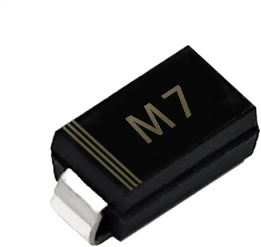
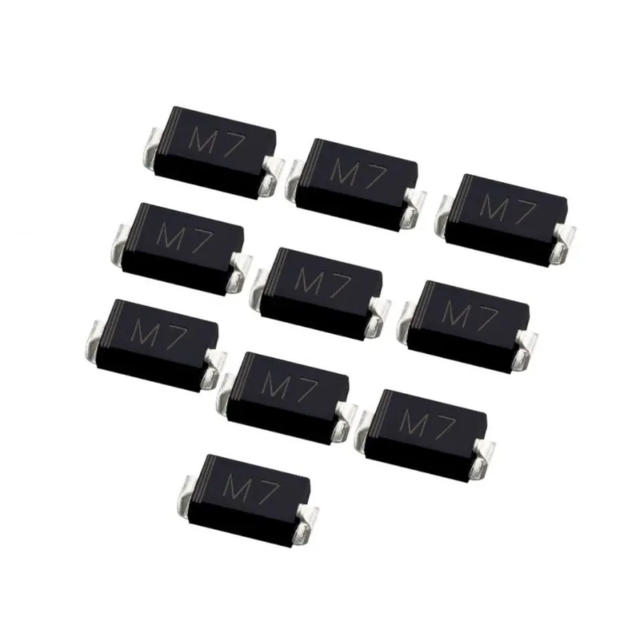
The M7 diode is a surface-mount rectifier diode, characterized by its compact SMA/DO-214AC package and designed to convert alternating current (AC) into direct current (DC). As a rectifier, the M7 diode facilitates current flow in only one direction, making it a crucial component in various electronic circuits. It's a popular choice due to its high efficiency and ability to handle significant power within its small form factor.
Specifically, the M7 is part of the SMA series, a common package for surface-mount diodes. It is primarily used for rectification in power supply circuits due to its 1 amp current capability and 1000 volt peak reverse voltage.
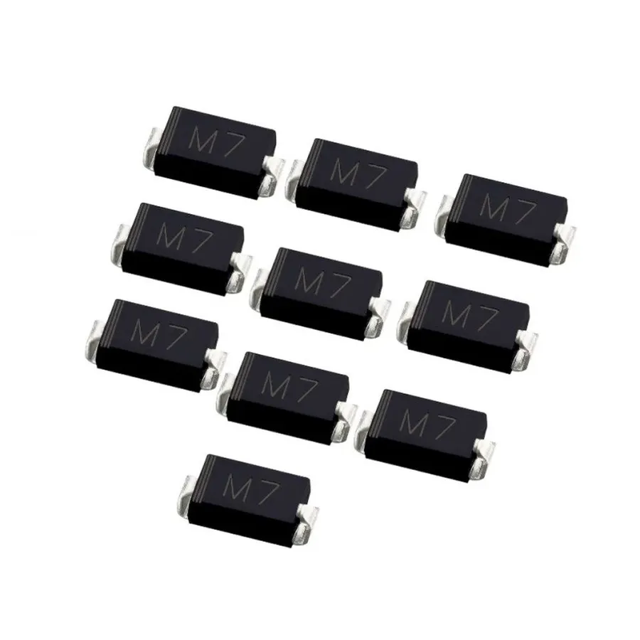
The M7 diode is characterized by several key electrical specifications that dictate its performance and suitability for various applications. Understanding these parameters is critical for proper component selection and circuit design. The M7 is a surface-mount rectifier diode, meaning it is designed to allow current to flow predominantly in one direction while blocking it in the opposite direction. Its key specifications include forward current, peak reverse voltage, forward voltage drop, surge current capability, and typical operating temperatures.
| Parameter | Value | Description |
|---|---|---|
| Forward Current (IF) | 1A | The maximum continuous current the diode can safely handle in the forward direction. |
| Peak Reverse Voltage (VRRM) | 1000V | The maximum reverse voltage the diode can withstand without breaking down. |
| Forward Voltage Drop (VF) | ~1.1V (at 1A) | The voltage drop across the diode when it is conducting in the forward direction. This value can vary with temperature and current levels. |
| Surge Current (IFSM) | 30A (typically, for 8.3ms) | The maximum non-repetitive peak current the diode can withstand for a short duration. This is crucial for handling inrush currents. |
| Operating Temperature (TJ) | -55°C to +150°C | The range of temperatures within which the diode is designed to operate reliably. Exceeding these limits may cause device failure or reduced performance. |
It's important to note that these values are typically provided under specific testing conditions, as specified in the M7 diode datasheet. Real-world performance may vary based on the application's environment and circuit design. Engineers should refer to the datasheet for the most accurate and detailed specifications, and should consider derating these values to ensure reliable operation in real-world applications. The M7's robust parameters, specifically its high peak reverse voltage and surge current capacity, make it a suitable choice for various power rectification applications.
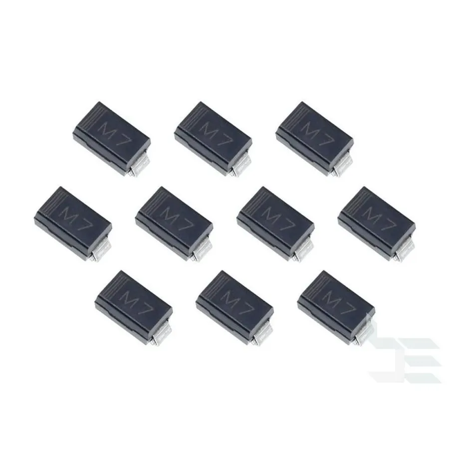
The M7 diode, a compact surface-mount rectifier, finds extensive application in various electronic circuits due to its efficient rectification capabilities. It's particularly favored in situations requiring a balance between size, cost, and performance, and are designed to convert AC to DC.
Here are some typical applications:
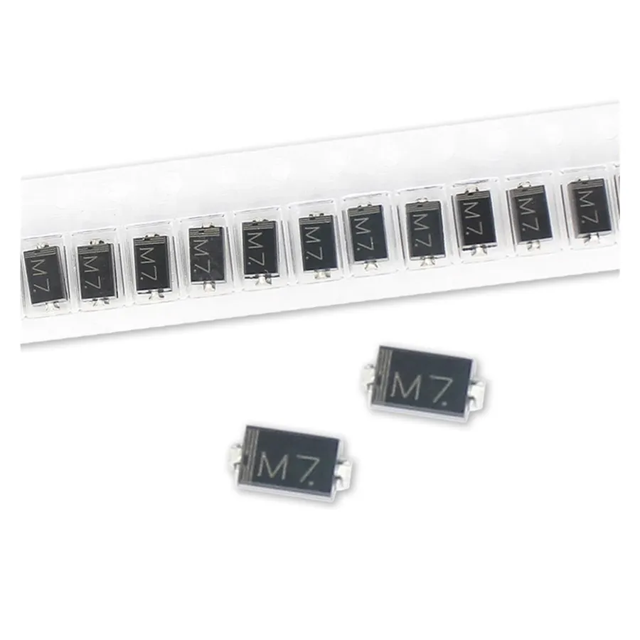
The M7 diode and the 1N4007 diode are both common rectifier diodes, but they differ significantly in their packaging and, consequently, their typical applications. The M7 is a surface-mount device (SMD), while the 1N4007 is a through-hole component. This fundamental difference drives their usage in modern electronics.
| Feature | M7 Diode | 1N4007 Diode |
|---|---|---|
| Package Type | Surface Mount (SMA/DO-214AC) | Through-Hole (DO-41) |
| Forward Current (IF) | 1A | 1A |
| Peak Reverse Voltage (VRRM) | 1000V | 1000V |
| Forward Voltage Drop (VF) @ 1A | ~1.1V | ~1.1V |
| Surge Current (IFSM) | 30A | 30A |
| Typical Application | SMD circuit boards, compact designs | Legacy designs, prototyping, through-hole PCBs |
| Mounting | Automated SMT assembly | Manual soldering |
| Size | Small, compact | Larger, bulkier |
The M7 diode is designed for modern high-density circuit board assembly using surface mount technology, which allows for smaller designs and automated manufacturing. In contrast, the 1N4007 diode, with its through-hole design, is typically used in older equipment, prototyping, or applications where manual soldering is preferred.
While both diodes have similar electrical specifications such as forward current and peak reverse voltage, their physical forms dictate their suitability for specific applications. The M7 is advantageous in applications where space is a premium and in high-volume manufacturing where automatic assembly is standard practice, while the 1N4007 is better suited for legacy equipment and applications where the through hole component is required.
When the M7 diode is unavailable, identifying suitable replacements is crucial for maintaining circuit functionality. This section explores alternative surface mount rectifier diodes with comparable electrical characteristics, aiding in component sourcing and ensuring circuit performance.
The primary consideration when seeking an M7 diode equivalent is matching or exceeding its key specifications: a forward current of 1A, a peak reverse voltage of 1000V, and similar forward voltage drop characteristics. Below are several suitable alternatives.
| Component | Package | Forward Current (A) | Peak Reverse Voltage (V) | Forward Voltage Drop (V, Typical) |
|---|---|---|---|---|
| RS1M | SMA (DO-214AC) | 1 | 1000 | 1.1 |
| US1M | SMA (DO-214AC) | 1 | 1000 | 1.1 |
| ES1M | SMA (DO-214AC) | 1 | 1000 | 1.1 |
| GS1M | SMA (DO-214AC) | 1 | 1000 | 1.1 |
Important Considerations: * **Datasheet Verification:** Always consult the datasheet of the alternative diode to confirm its electrical parameters precisely match the requirements of your application. * **Package Compatibility:** Ensure that the replacement's package (typically SMA/DO-214AC) is compatible with the existing circuit's footprint. * **Temperature Characteristics:** Verify the replacement's operating temperature range to be compatible with the application. * **Forward Voltage Drop:** While most alternatives exhibit a forward voltage drop near 1.1V, checking the datasheet is vital, as variations can impact circuit performance, especially in low-voltage applications. * **Availability and Cost:** Component availability and price may also influence your choice of replacement. Some alternatives can be more readily available or cost effective, depending on the supplier.
This section addresses common inquiries regarding the M7 diode, clarifying its function, alternatives, and distinctions from similar components, thereby ensuring a comprehensive understanding for users.
Testing an M7 diode is a crucial step to ensure its proper functionality within a circuit. This process, typically conducted using a multimeter, verifies the diode's ability to conduct current in one direction while blocking it in the opposite, a fundamental characteristic of rectifying diodes.
Here's a practical guide on how to test the M7 diode:
Common issues encountered during testing can include a shorted diode, which will have a voltage drop (low resistance) in both directions, or an open diode, which will show no voltage drop (high resistance) in either direction. In circuit testing can be influenced by other components, so it's often best to desolder the diode from circuit for precise measurements.

Understanding the M7 diode's symbol and pinout is crucial for correct circuit design and assembly. The M7, a surface-mount device, has a standardized symbol and physical layout that dictates its proper orientation within a circuit.
The M7 diode symbol and pinout are essential for ensuring the correct placement in a circuit. The following description will clarify this, using an image of the symbol and a detailed description of the pinout.
The schematic symbol for a diode consists of a triangle pointing towards a vertical line. This indicates the direction of conventional current flow through the diode. The triangle side corresponds to the anode (+), while the line side indicates the cathode (-).
For the M7 diode, which is typically packaged in a SMA/DO-214AC surface mount package, the pinout is identifiable through a marking on the diode body. There is a line or band on the component, typically near one of the short sides of the device. This band indicates the cathode end of the M7 diode.
The cathode must be connected to the lower voltage potential relative to the anode for the diode to function in its forward-bias mode, where it allows current to flow. Connecting it in the reverse-bias direction inhibits current flow and can be used for protection circuits.
Selecting the correct M7 diode for a specific application hinges on a clear understanding of the circuit's demands. The primary considerations revolve around the diode's current and voltage ratings, as well as its operating environment. This section provides guidance on how to determine the most important specifications for various electrical applications to ensure optimal performance and circuit longevity.
| Parameter | Consideration |
|---|---|
| Forward Current | Must be greater than circuit's continuous current draw. Select with a safety margin if current is near the limit or can exceed the rating. |
| Peak Reverse Voltage | Must be greater than maximum reverse voltage in the circuit. Consider transient voltages and select with safety margin. |
| Operating Temperature | Diode's operating temperature range must encompass the project's environmental range. |
| Surge Current | Surge current must be within the diode's limit. Check start up conditions and transient currents. |
| Forward Voltage Drop | Consider the forward voltage drop for power loss calculation and voltage regulation. |
The M7 diode, though small, is a powerful workhorse in electronics, essential for rectifying alternating current into direct current. Understanding its key specifications and applications, alongside its relationship to other diodes, allows you to effectively design and repair your electronic projects. With its reliable 1A, 1000V specifications in a compact surface mount package, the m7 diode continues to enable electronics engineers in building advanced devices, underscoring its significance in modern circuitry.

