Understanding the SCR Transistor: Power Control at Your Fingertips
2025.02.11
In our technology-driven world, from dimming lights to controlling industrial motors, we often rely on devices that regulate electrical power. At the heart of many of these systems lies the SCR transistor, a semiconductor device that, like a sophisticated gate, dictates the flow of current. This article delves into the world of the SCR transistor, explaining its intricate mechanisms, various applications, and distinct characteristics, highlighting its crucial role in modern power electronics.
What is an SCR Transistor?
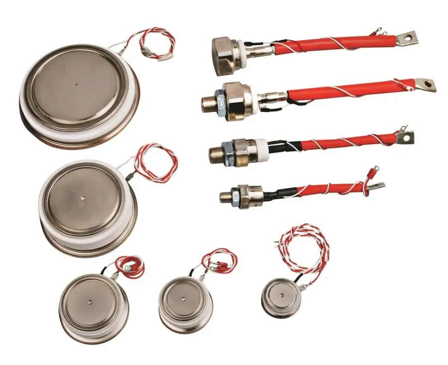
SCR Thyristor
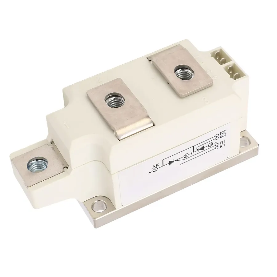
The Silicon Controlled Rectifier (SCR), often referred to as an SCR transistor, is a four-layer semiconductor device belonging to the thyristor family. Functioning as a unidirectional switch, it allows current flow in only one direction and exhibits a unique latching behavior, making it suitable for power control applications.
SCR Transistor Structure and Symbol
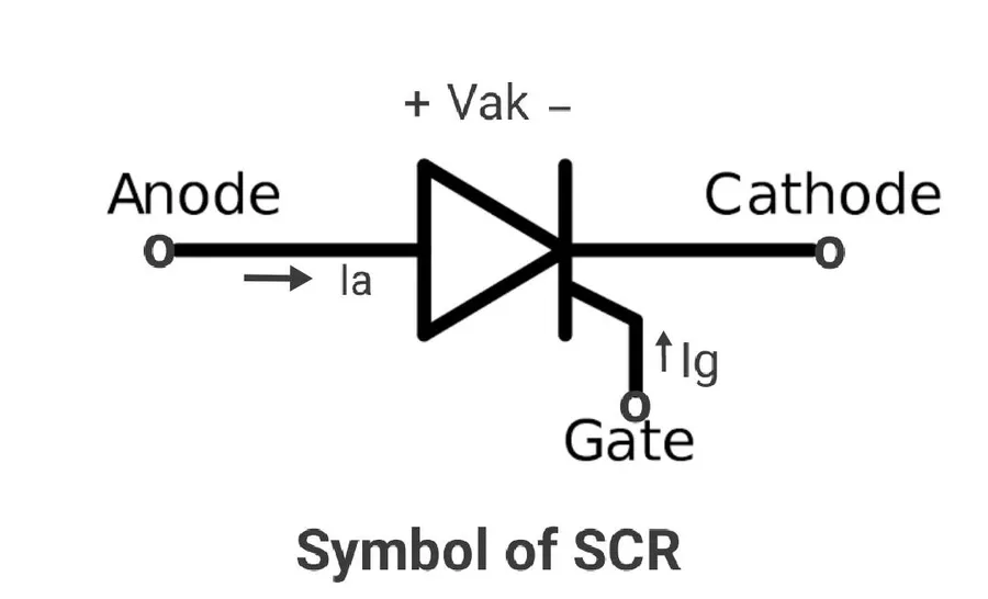
SCR Symbol
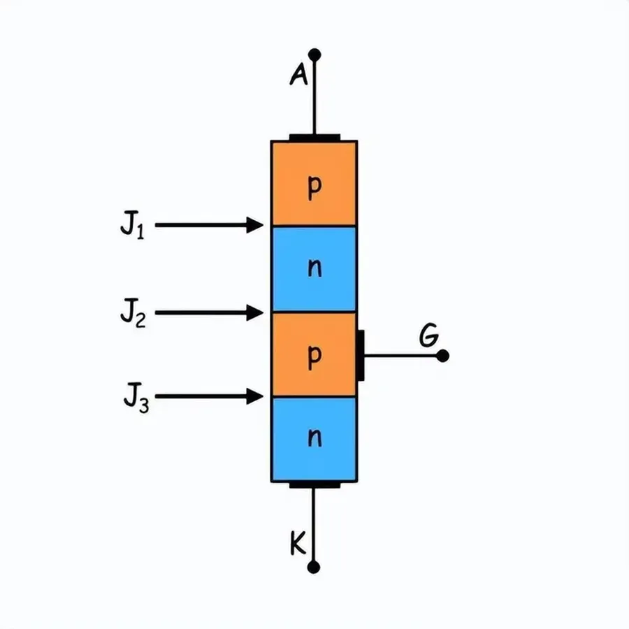
The Silicon Controlled Rectifier (SCR) is a four-layer semiconductor device with a PNPN structure, forming the basis for its unique switching characteristics. This layered arrangement dictates its function as a unidirectional switch, critical in power control applications. Understanding this structure is key to comprehending its operation.
The SCR possesses three terminals that govern its behavior: the Anode (A), Cathode (K), and Gate (G). The Anode is the positive terminal, where current enters when the SCR is conducting. The Cathode is the negative terminal, where current exits the device. The Gate, typically connected to the P-type layer closest to the Cathode, is the control terminal that triggers the SCR into a conducting state.
The schematic symbol for an SCR is a crucial element for understanding circuit diagrams. It is represented by a diode symbol with an additional control gate terminal connected to the corner of the angled line, clearly illustrating its function as a unidirectional current controller, with the gate controlling the switching action, not current magnitude when the device is fully turned on.
Terminal
Description
Layer Connection
Anode (A)
Positive terminal; current enters when conducting
P-type layer
Cathode (K)
Negative terminal; current exits when conducting
N-type layer
Gate (G)
Control terminal; triggers conduction
P-type layer closest to Cathode
The Working Principle of SCR Transistor
SCR Circuit
The Silicon Controlled Rectifier (SCR) operates as a unidirectional switch, primarily controlled by a gate current. Understanding its working principle involves analyzing its triggering mechanism, latching behavior, and operational modes, which are critical for utilizing it effectively in various power control applications.
The SCR has three operational modes, which are: Forward Blocking Mode, Forward Conduction Mode, and Reverse Blocking Mode.
Forward Blocking Mode In this mode, the anode is positive with respect to the cathode, but no gate current is applied. The SCR blocks current flow, behaving like an open circuit. The device has high resistance and only a small leakage current flows through it. The SCR will remain in the forward blocking mode until a sufficient gate pulse triggers it into the conducting state or the anode-cathode voltage exceeds the forward breakover voltage.
Forward Conduction Mode To initiate forward conduction, a positive current pulse is applied to the gate. This triggers the SCR to switch on, reducing the internal resistance and allowing a large current to flow from the anode to the cathode. Once triggered, the SCR will continue to conduct even if the gate current is removed. It remains in this mode as long as the current exceeds the holding current.
Reverse Blocking Mode In reverse blocking mode, the anode is negative with respect to the cathode, and the SCR blocks current flow regardless of the gate signal. Only a very small reverse leakage current flows. This is the natural blocking state for the device when it's used in AC circuits, during the half cycle that it is not intended to conduct.
The 'latching' behavior of the SCR is a key characteristic. Once triggered into conduction, the SCR will remain conducting as long as the current through it (anode-cathode current) is above a specific threshold called the 'holding current'. To turn off the SCR, the current must be reduced below this holding current, or the anode-cathode voltage must be reduced to zero by an external switching mechanism. This behavior makes SCR suitable for applications where switching action is required, as they maintain a stable current after they are triggered by an external gate signal, and do not require a continuous gate current to be turned on.
SCR Transistor vs. Traditional Transistors
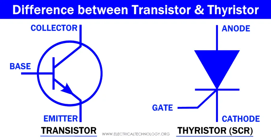
SCR vs Transistor
While the Silicon Controlled Rectifier (SCR) is often referred to as an SCR transistor, it's crucial to understand the distinctions between it and traditional transistors such as Bipolar Junction Transistors (BJTs) and Field-Effect Transistors (FETs). These differences dictate their applications and suitability for various electronic circuits. The core difference lies in their switching behavior, control mechanisms, and power handling capabilities.
Feature
SCR
BJT
FET
Switching Behavior
Latching (Once triggered, stays on until current is interrupted)
Continuous control (Current flow controlled by base/gate current)
Continuous control (Current flow controlled by gate voltage)
Control Mechanism
Gate current pulse to trigger ON; current interruption to turn OFF
Base current controls collector current
Gate voltage controls drain current
Current Flow
Unidirectional
Bidirectional (can conduct in both directions in some configurations)
Bidirectional
Power Handling
High, suitable for high-power switching applications
Moderate, suitable for amplification and switching
Moderate to high, suitable for switching and amplification
Turn-off Method
Requires reducing current below holding current or forced commutation
Reduce base current to turn off
Remove gate voltage to turn off
Typical Applications
Power control, phase control, light dimmers, motor control
Amplification, switching, signal processing
Switching, amplification, voltage control
In summary, SCRs are optimized for high-power switching applications where latching behavior is advantageous, while BJTs and FETs offer more flexibility in controlling current and voltage for amplification and continuous switching applications. The choice between them depends largely on the specific requirements of the electronic circuit.
Silicon Controlled Rectifier (SCR) Applications
SCR Motor Control
Silicon Controlled Rectifiers (SCRs), with their unique latching characteristic and high current handling capabilities, are pivotal in a wide array of power control applications. These applications leverage the SCR's ability to switch high currents with a small gate signal, making them indispensable in various industrial and consumer electronic devices.
Light Dimmers SCRs enable efficient control of light intensity by varying the conduction angle of the AC waveform. This method reduces power consumption and provides smooth, adjustable light levels. The SCR acts as a switch, allowing current to flow only during the portion of the AC cycle where the gate signal is applied.
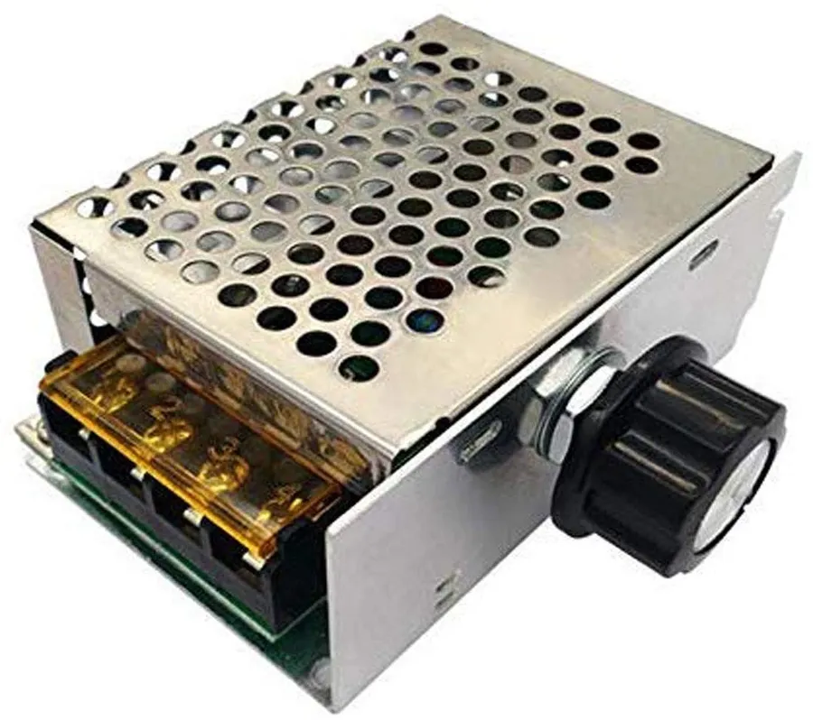
Motor Speed Controllers In motor speed control, SCRs are employed in phase-controlled rectifiers. By altering the firing angle of the SCR, the average voltage applied to a motor can be regulated. This technique is fundamental in controlling the speed of DC motors, offering robust and precise speed management. Often used in appliances and industrial machinery.
Power Inverters SCR-based inverters convert DC power to AC power. They operate by switching the DC input to create an alternating output, which can be used to power AC devices. SCRs provide a cost-effective and rugged solution for medium-to-high power applications, like uninterruptible power supplies (UPS) or industrial drives.
Battery Chargers SCRs are integral in the design of battery charging circuits. They control the charging current delivered to the battery by rectifying the incoming AC supply and regulating the current output. Their high current capacity makes them suitable for handling the high charging currents required for large batteries.
Welding Equipment SCRs are also used to control the power in welding equipment, offering precise current control. Their ability to handle high currents and their robustness make them suitable for the harsh environments typical of welding processes.
Phase Control Circuits SCRs are essential in phase control circuits, which adjust the conduction angle of the AC cycle to regulate power delivery. This application is critical in many industrial processes, such as heating and lighting control. The SCR's ability to switch on at a specific point in the AC cycle allows precise power modulation.
Advantages and Disadvantages of SCR Transistors
SCR Power Supply
Silicon Controlled Rectifiers (SCRs), while powerful switching devices, present a unique set of advantages and disadvantages that must be carefully considered for any application. Their benefits stem from their inherent design, while their limitations often require additional circuit design to mitigate.
Feature
Advantages
Disadvantages
Current Handling
High current handling capabilities, suitable for high-power applications.
Unidirectional current flow, preventing reverse current operation.
Triggering
Simple gate triggering mechanism requires only a pulse of current to initiate conduction.
Requires a separate commutation circuit to turn off, especially in DC circuits.
Efficiency
High efficiency due to low forward voltage drop when conducting.
Latching behavior requires external methods to stop conduction once triggered.
Switching Behavior
Fast switching speeds are possible.
Not suitable for applications requiring precise analog control.
Reliability
Robust and reliable under high voltage and current conditions.
Susceptible to damage from over-voltage or excessive gate current if not handled properly.
Cost
Generally cost-effective for high power applications.
Requires additional circuitry for safe and reliable operation.
Frequently Asked Questions About SCR Transistors
This section addresses common inquiries regarding SCR transistors, providing clear and concise answers to enhance understanding of their functionality and application.
What is an SCR transistor? An SCR (Silicon Controlled Rectifier) is not a transistor in the traditional sense but a type of thyristor. It's a four-layer (PNPN) semiconductor device that acts as a unidirectional switch, meaning it allows current flow in only one direction once triggered. It is primarily used for high-power switching applications.
What is the function of an SCR? The primary function of an SCR is to act as an electronically controlled switch for high-power applications. It remains in an 'off' state until a gate current is applied, at which point it switches 'on' and remains in the conducting state (latched) even after the gate current is removed. It will only stop conducting when the current through the device drops below its holding current. Due to its switching characteristics, it's commonly used in applications requiring phase control.
What is the difference between an SCR and a traditional transistor (BJT or FET)? The key difference lies in their switching behavior. Traditional transistors (BJTs and FETs) provide continuous control over the current flow by varying the base/gate current or voltage. SCRs, however, operate as latching switches; they either conduct fully or are completely off. Once triggered, they remain conducting until the current drops below the holding current and cannot be controlled by the gate signal. SCRs are also designed for handling much higher power levels compared to most transistors.
Is an SCR more suited for AC or DC circuits? While SCRs can be used in both AC and DC circuits, they are particularly suited for AC power control applications. In AC circuits, the natural zero-crossing of the AC waveform can commutate, or turn off the SCR when current drops to zero. In DC circuits, an additional commutation mechanism is required to force the current to drop below the holding current to turn off the SCR. Therefore they are more commonly used for AC circuits where the natural zero crossing behavior turns the SCR off.
Why are SCRs commonly used as power switching devices? SCRs are preferred for power switching due to their ability to handle high current and voltage levels, along with their latching behavior. They require only a small gate current to trigger, which can control large power loads. This makes them highly efficient for applications like light dimmers, motor control, and power converters. They also exhibit low on-state voltage drop which reduces power dissipation.
What does the SCR transistor symbol look like? The standard SCR symbol consists of an arrow, which represents the direction of current flow, pointing from the anode to the cathode. There is a line on the cathode side which corresponds to a typical diode, there is also a single arrow which is the gate. The anode is typically labelled 'A', the cathode is 'K', and the gate is 'G'. This unique symbol distinguishes it from standard diodes and transistors.
What are the typical characteristics of an SCR? Typical SCR characteristics include forward blocking voltage (the maximum forward voltage the SCR can block), holding current (the minimum current required to keep the SCR conducting), and gate trigger voltage and current (the values required to switch the SCR on). They exhibit a very low forward voltage drop when conducting and have high current capabilities. In addition they are a unidirectional devices and the current can only flow from the anode to the cathode and not the other way around.
Practical Considerations when Using SCR Transistors
Selecting and implementing SCR transistors effectively requires careful attention to several key factors. These include understanding the device's voltage, current, and gate requirements, proper thermal management, careful circuit design, and mitigating transient issues using snubber circuits. These aspects are critical for reliable and efficient operation of any circuit employing SCRs.
Choosing the Right SCR Selecting an appropriate SCR involves considering its voltage, current, and gate trigger requirements. The forward blocking voltage of the SCR must be greater than the maximum applied voltage in your application. The RMS current rating needs to exceed the expected continuous current. Finally, ensure the gate trigger current is compatible with your control circuitry. Overrating these parameters is crucial to ensuring reliability and preventing premature failure of the SCR.
Thermal Management SCRs generate heat during operation, especially when conducting high currents. Adequate heat sinking is imperative to prevent overheating and ensure the SCR's longevity. The datasheet for the SCR will contain thermal resistance information, which should be used when designing heat sinks and selecting a suitable device.
Circuit Design When designing with SCRs, it is crucial to ensure that the gate drive circuitry can provide sufficient current to trigger the SCR reliably. Additionally, consider the necessary components needed to trigger the device and any commutation circuits required to turn off the SCR for DC applications. Designing the triggering circuit for reliability in various operating conditions is essential to the overall success of the circuit.
Snubber Circuits Snubber circuits, typically composed of resistors and capacitors, are crucial for limiting the rate of voltage change (dv/dt) across the SCR. This helps to prevent unwanted, premature triggering that can occur due to transient voltage spikes. These circuits are placed across the SCR and protect it from these issues.
The SCR transistor stands as a vital component in power electronics, enabling efficient control of electrical current. Its unique properties such as latching and high current capacity, make it ideal for a wide array of applications, from simple light dimmers to complex industrial motor controls. Understanding how the SCR transistor functions and where it excels, helps engineers leverage the technology for innovative power system designs. Although it might not be as universal as other transistors, its specific niche and capabilities ensure its enduring relevance in modern electronics.