In the world of electronics, capacitors play a crucial role in storing electrical energy. You've likely seen capacitors with markings like '2.2 uF' or '100 uF'. But what exactly does 'uF' mean, and why is it so important? The 'uF' signifies microfarads, a unit of capacitance that impacts how a capacitor stores and releases charge. This article will explore the meaning of uF in capacitors and how it relates to real-world applications.
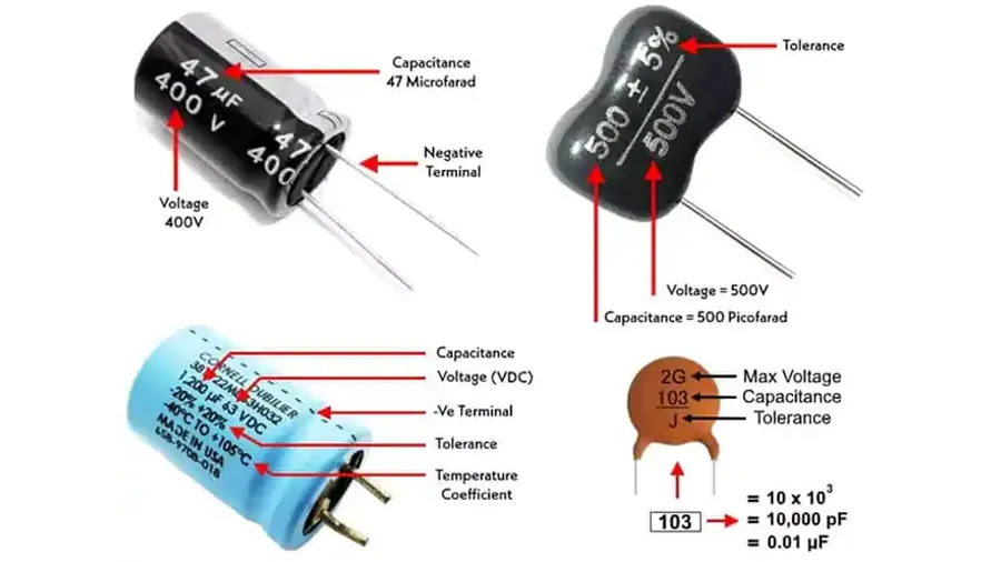
The symbol 'uF' represents microfarad, a unit of capacitance used to quantify a capacitor's ability to store an electrical charge. A farad (F) is a large unit, making the microfarad (1 uF = 10⁻⁶ F) the more practical and commonly used unit in electronics. Understanding this unit is fundamental when dealing with capacitors in circuit design and analysis.
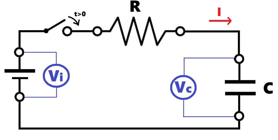
The microfarad (uF) value of a capacitor directly correlates with its ability to store electrical charge; a higher uF rating indicates a greater capacity to accumulate charge at a given voltage. This relationship is fundamental to understanding how capacitors function within electronic circuits.
The analogy of a capacitor as a rechargeable battery is useful: a higher uF value corresponds to a 'larger battery,' capable of holding more electrical energy at the same voltage. This stored charge is then available for the circuit to use.
| Characteristic | Lower uF Value | Higher uF Value |
|---|---|---|
| Charge Storage | Lower capacity | Higher capacity |
| Analogy | Smaller battery | Larger battery |
| Impact on Circuit | Less energy available to the circuit | More energy available to the circuit |
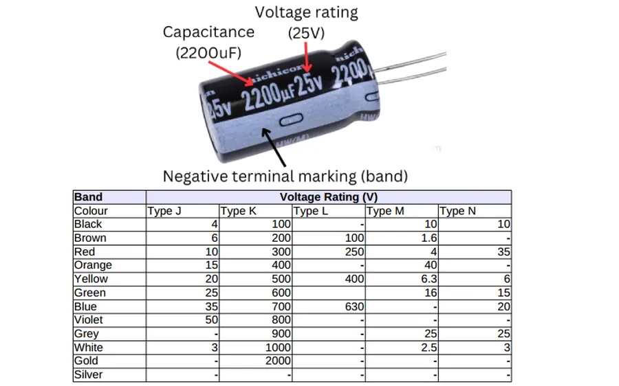
Capacitance, measured in microfarads (uF), and voltage rating are two independent but crucial parameters of a capacitor. The uF value quantifies the capacitor's ability to store electrical charge, while the voltage rating indicates the maximum voltage it can safely withstand without damage or failure. A common misconception is that higher uF values correlate with higher voltage ratings, which is incorrect.
| Parameter | Description | Unit | Impact of Value |
|---|---|---|---|
| Capacitance (uF) | Measure of charge storage capability | Microfarad (uF) | Higher uF, greater charge storage, impacts filtering, timing |
| Voltage Rating | Maximum safe voltage the capacitor can handle | Volts (V) | Higher voltage, greater resistance to electrical breakdown |
It's important to note that two capacitors can have the same voltage rating but significantly different uF values, and vice versa. For example, a capacitor rated at 2.2 uF might have a 50V rating, while a 10uF capacitor could also have the same 50V rating. Therefore, consider both specifications independently when selecting a capacitor for a specific circuit application.
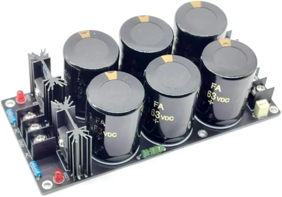
Capacitors, particularly those with small microfarad (uF) values such as 0.1 uF, play a crucial role in filtering and decoupling within electronic circuits. Their primary function is to mitigate noise and voltage fluctuations, thereby ensuring the stable and reliable operation of sensitive components, such as microchips.
The effectiveness of a capacitor in filtering and decoupling is directly related to its capacitance (uF). Lower uF values are generally suitable for filtering high-frequency noise, while higher values are more effective at smoothing out low-frequency variations and providing local energy storage.
Decoupling capacitors, often placed close to integrated circuits (ICs), act as localized charge reservoirs. They rapidly supply current to the IC when it demands it, preventing dips in the supply voltage and reducing noise that might interfere with the IC's operation.
| Application | Typical uF Value | Function | Noise Mitigation |
|---|---|---|---|
| High-Frequency Noise Filtering | 0.001 uF - 0.1 uF | Suppresses high-frequency signals | Excellent |
| Decoupling | 0.1 uF - 10 uF | Provides local charge storage, minimizes supply voltage dips | Good |
| Power Supply Smoothing | 10 uF - 1000 uF | Reduces low frequency ripples | Moderate |
A 0.1 uF capacitor is a common choice for decoupling because it provides a balance between cost, size, and performance in handling the high-frequency noise typically found in digital circuits. However, the specific capacitance value required will vary depending on the specific circuit design and operating frequency. It's crucial to check datasheets and follow circuit design guidelines when selecting decoupling capacitors.
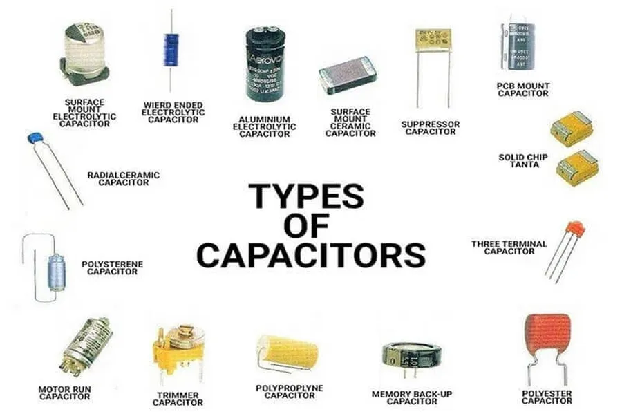
Capacitor types significantly influence the available range of capacitance values, measured in microfarads (uF), due to their distinct construction and materials. Each type caters to specific application needs. Generally, ceramic capacitors are characterized by smaller uF values, while electrolytic capacitors offer a wide range of higher capacitance values.
| Capacitor Type | Typical uF Range | Characteristics | Common Applications |
|---|---|---|---|
| Ceramic | 1 pF to 10 uF | Small size, low cost, low ESR | Bypass, coupling, timing |
| Electrolytic | 0.1 uF to 100,000+ uF | High capacitance, polarized | Power supply filtering, energy storage |
| Tantalum | 0.1 uF to 1000 uF | Stable, compact, low ESR | Power supply, decoupling |
| Film | 1 nF to 100 uF | High precision, low loss | Audio, precision timing |
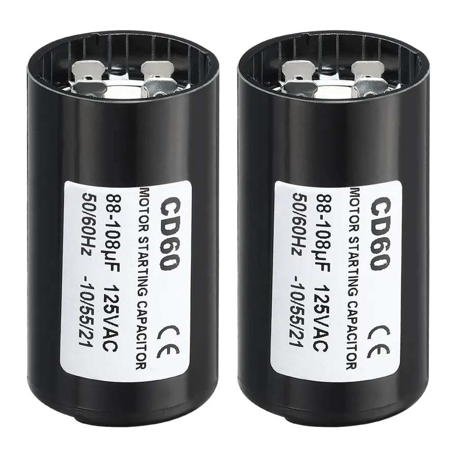
In single-phase AC induction motors, an auxiliary winding is employed to initiate rotation. Unlike three-phase motors that inherently possess a rotating magnetic field, single-phase motors require a phase shift to overcome static friction. Larger microfarad (uF) capacitors, often ranging from tens to hundreds of uF, are crucial in creating this necessary phase shift, enabling the motor to start reliably. These capacitors are typically employed only during the start-up phase of operation.
| Parameter | Description | Typical Value Range |
|---|---|---|
| Capacitance (uF) | Determines the magnitude of phase shift and starting torque | Tens to hundreds of uF |
| Voltage Rating | Maximum allowable voltage that the capacitor can handle without damage | Match with motor supply voltage or a higher rating |
| Type | Typically electrolytic or film capacitors are used for start applications | Electrolytic or film |
| Application | Used temporarily during motor startup to provide torque | Motor starting |
Understanding the role of microfarads (uF) in capacitors is crucial for effective circuit design and troubleshooting. This section addresses common questions regarding uF values, their implications, and proper usage, ensuring a clear understanding of this fundamental parameter.
While microfarad (uF) is the most commonly used unit for capacitance, millifarad (mF) also exists, although it's less frequently encountered in practical applications. It's vital to understand their relationship to avoid errors. Additionally, the term MFD, often found on older components, can add confusion. This section clarifies these terms.
| Unit | Symbol | Relationship to Farad (F) | Relationship to uF | Common Use Cases |
|---|---|---|---|---|
| Microfarad | uF | 1 uF = 10-6 F | 1 uF = 1 uF | Most common for capacitors in electronics. |
| Millifarad | mF | 1 mF = 10-3 F | 1 mF = 1000 uF | Occasionally found in larger capacitors. |
| MFD | MFD | 1 MFD = 10-6 F | 1 MFD = 1 uF | Often used on motor start capacitors as an alternative to uF. |
Note: MFD is equivalent to uF, and is most likely used in motor starting capacitors, it's not the same as mF (millifarad). Always check the units carefully when replacing capacitors.
Selecting the appropriate uF capacitor is paramount for ensuring the optimal performance and reliability of electronic circuits. The capacitance value, measured in microfarads (uF), directly influences a circuit's behavior, particularly in areas such as filtering and energy storage. Incorrect uF values can lead to malfunctions or complete circuit failure; therefore, careful selection based on circuit requirements is essential.
Several factors must be considered when selecting a capacitor. Always prioritize the manufacturer's specifications, schematic diagrams, and application-specific requirements.
The selection of a capacitor is not solely dependent on the uF value; other factors like the voltage rating, temperature coefficient, physical size, and the type of capacitor are equally important for its effective functioning within the application requirements. Use of improper capacitor values can result in inefficient circuit performance or, in some situations, complete failure.
Understanding the 'uF' value on a capacitor is fundamental to any electronics work. The uF, representing microfarads, dictates how much electrical charge a capacitor can store, playing a key role in filtering, decoupling, and motor starting applications. By understanding uF, and choosing the correct components, you can ensure that electronic circuits function optimally and safely. Whether it's a small 0.1 uF ceramic capacitor or a large 65 uF motor start capacitor, their specific uF ratings play a critical role in the intended application.

