In the vast world of electronics, seemingly small components play incredibly important roles. Take, for example, the humble 120 ohm resistor, a component often unseen but critical for many applications. You may not notice its existence in your daily life, but the technology you use relies on it in many ways. From your vehicle's CAN network to various industrial equipment, the 120 ohm resistor is often employed as a crucial component, ensuring the stability of signal transmission by acting as a key element in the bus communication. This article will explore the role of a 120 ohm resistor in various systems and discuss why it is vital for reliable performance.
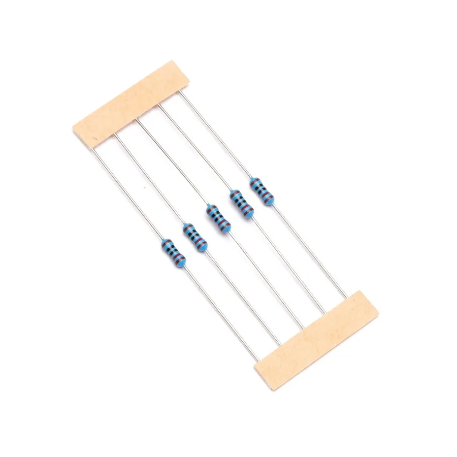
A 120 ohm resistor is a fundamental electronic component designed to impede the flow of electrical current, presenting a resistance of 120 ohms. This specific value plays a critical role in various circuits, particularly in communication networks. Resistance, measured in ohms, is the opposition to current flow; it's directly proportional to the voltage across the resistor and inversely proportional to the current passing through it, as defined by Ohm's Law (V=IR). The rating value of 120 ohms signifies the precise degree of this opposition.
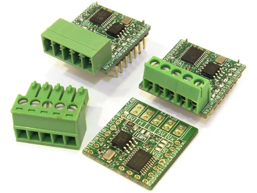
In Controller Area Network (CAN) bus systems, 120 ohm resistors are crucial as termination resistors, primarily functioning to prevent signal reflections and maintain the integrity of data transmission. Signal reflections occur when transmitted signals encounter impedance mismatches, causing a portion of the signal to bounce back, corrupting data and potentially disrupting communication across the network. The strategic placement of these resistors effectively absorbs the signal energy at the end of the bus, preventing reflections and ensuring that the transmitted data is received accurately.
These reflections can manifest as data corruption, reduced communication distance, and overall system instability, all of which are unacceptable in the typically noise-sensitive applications of a CAN bus. The 120 ohm resistor, when correctly implemented, matches the characteristic impedance of the CAN bus, acting like an 'end stop' for the electrical signals.
By reducing these reflections, the bus maintains a clean signal, improving reliability and accuracy of data communication.
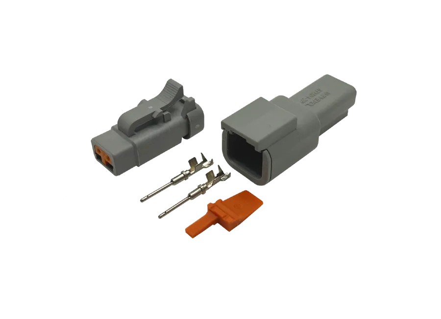
In a Controller Area Network (CAN) bus system, the implementation of two 120 ohm resistors, positioned at each extremity of the bus, is not arbitrary but a fundamental design choice for ensuring signal integrity and preventing data corruption. These resistors act as termination points, critical to absorbing signals, rather than allowing them to reflect back along the bus.
The need for two 120 ohm resistors arises from the physics of signal transmission. When electrical signals propagate down a transmission line (like a CAN bus cable), they encounter the end of the line. If the line is not properly terminated, these signals reflect, causing distortion and interference, analogous to echoes on a sound wave. This can lead to data errors, instability in communication, and, ultimately, network failures.
Each 120 ohm resistor matches the characteristic impedance of the CAN bus cable. This impedance matching ensures that the transmitted signal is absorbed completely at the ends of the bus, preventing reflections. If only one resistor were present, a single termination point would only absorb reflections coming from that end, and signals originating from the other end would still be reflected. This incomplete termination results in a network that is prone to errors and unreliable.
The placement of the two 120 ohm resistors at opposite ends of the bus ensures that all signals, regardless of their source, encounter a termination resistor. This configuration allows the CAN bus system to operate with stability, maintaining the integrity of communication across the network and fulfilling a crucial role in the system's operation by preventing signal reflection and maintaining communication stability.

Beyond their critical role in CAN bus systems, 120 ohm resistors find applications in various other electronic circuits, primarily where signal integrity and impedance matching are paramount. These applications leverage the resistor's ability to effectively terminate transmission lines, prevent signal reflections, and ensure accurate signal transmission.
Here's a breakdown of common applications:
Examples of devices that use 120 ohm resistors include electronic control units (ECUs) in vehicles, industrial automation equipment, networking hardware, and various types of test and measurement devices.
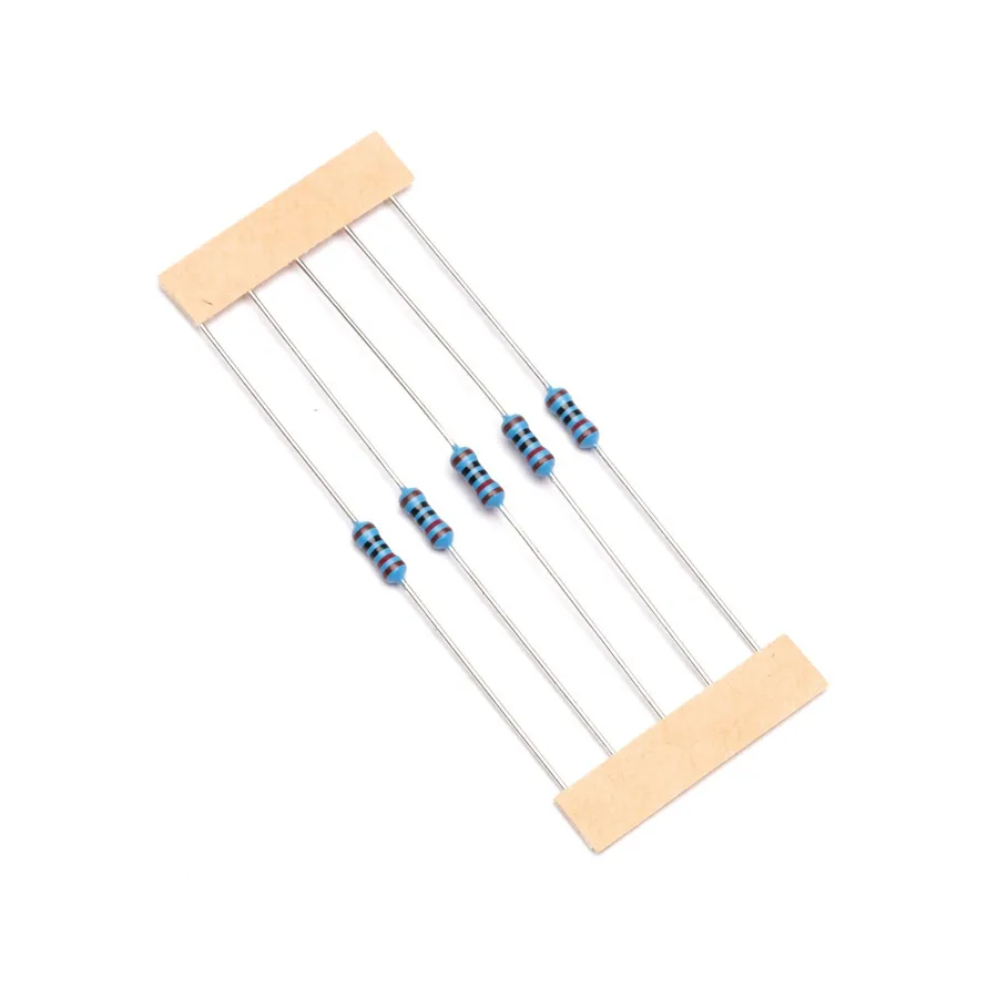
Selecting the correct 120 ohm resistor requires careful consideration of its specifications and type to ensure optimal performance within a given electronic circuit. These factors include physical form, power handling capabilities, precision, and size.
| Specification | Description | Importance |
|---|---|---|
| Type | Through-hole (axial) or Surface Mount Device (SMD) | Determines mounting method and physical size. Through-hole components are larger and easier for prototyping, while SMDs are compact for mass production. |
| Power Rating | Maximum power the resistor can dissipate (e.g., 1/8W, 1/4W, 1/2W) | Critical to prevent overheating and failure. Must exceed the expected power dissipation. |
| Tolerance | Permissible deviation from the nominal 120 ohm value (e.g., ±1%, ±5%) | Affects the precision of the resistor and circuit performance. Lower tolerance indicates higher precision. |
| Package Size (SMD) | Physical dimensions of the resistor (e.g., 0805, 0603, 1206) | Crucial for PCB layout. Must match the pad layout on the circuit board. |
| Temperature Coefficient | How much the resistance changes with temperature (PPM/°C) | Affects precision in changing temperatures and should be considered in systems with changing temperature |
When selecting a 120 ohm resistor, always ensure that the chosen power rating sufficiently exceeds the expected power dissipation within the circuit to prevent component failure. Tolerance should be selected based on the circuit's precision requirements.
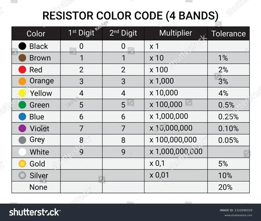
The color code on a resistor is a standardized system used to indicate its resistance value, tolerance, and sometimes its temperature coefficient. For a 120 ohm resistor, the color bands are typically arranged in a specific sequence to convey this information. Understanding this coding system is vital for correctly identifying and utilizing resistors in electronic circuits.
| Band | Color | Value |
|---|---|---|
| First Band | Brown | 1 |
| Second Band | Red | 2 |
| Third Band | Brown | Multiplier x 10^1 (x 10) |
| Fourth Band | Gold | Tolerance ±5% |
The color code for a 120 ohm resistor is Brown, Red, Brown, and Gold. The first three bands represent the resistance value while the fourth band represents the tolerance. Here's a breakdown of how to interpret each band:
Therefore, a resistor with color bands Brown, Red, Brown, Gold signifies a 120 ohm resistor with a 5% tolerance.
This section addresses common queries regarding 120 ohm resistors, providing clear, concise answers and practical guidance.
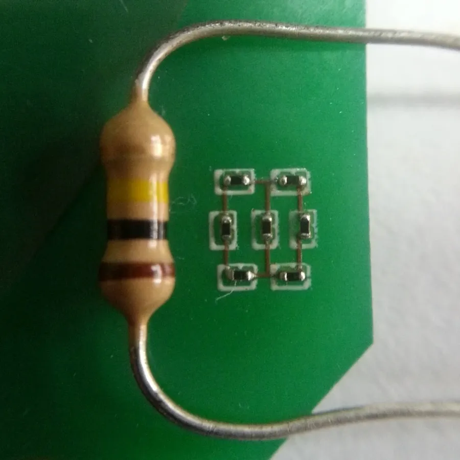
Proper handling and installation of 120 ohm resistors are essential to ensure optimal performance and reliability in electronic circuits. This section provides practical advice on how to correctly utilize these components, focusing on installation guidelines, PCB design considerations, and best practices for soldering and handling.
The 120 ohm resistor, while small, plays a critical role in ensuring stability and reliability in various electronic circuits, particularly in CAN bus networks. Understanding its function as a termination resistor is essential for anyone working with these systems. By preventing signal reflections and maintaining signal integrity, the 120 ohm resistor safeguards proper data transmission and ensures the efficient operation of various industrial equipment and vehicle networks. In the world of electronics, even the smallest component, like the 120 ohm resistor, can make a substantial difference, reminding us that meticulous planning and execution often determine success.

