Just like a flowing river, electricity needs a path to travel. A simple electric circuit is that path, a closed loop allowing energy to flow and power devices. This article will guide you through the essential components of a simple circuit, how they interact, and the steps for building your own. Get ready to demystify electricity and explore the magic within a simple electric circuit.
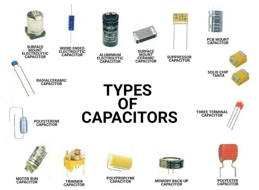
A simple electric circuit, the fundamental pathway for electrical current, comprises four essential elements: a power source (typically a battery), conductive wires, a load (such as a light bulb), and a switch. Each of these components plays a critical and interconnected role in enabling and controlling the flow of electricity within the circuit.
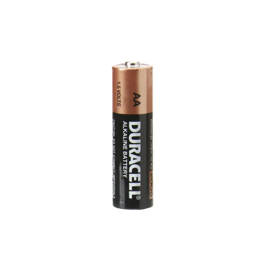
The power source is the heart of any electrical circuit, providing the necessary energy to drive the flow of electric current. In simple circuits, batteries are the most common power source, converting chemical energy into electrical energy through electrochemical reactions, thereby establishing a potential difference (voltage) that enables electrons to move.
| Battery Type | Voltage (V) | Description | Common Uses |
|---|---|---|---|
| AAA | 1.5 | Small cylindrical cells | Remote controls, small electronics |
| AA | 1.5 | Standard cylindrical cells | Flashlights, toys |
| C | 1.5 | Larger cylindrical cells | Larger flashlights, some toys |
| D | 1.5 | Largest common cylindrical cells | Portable radios, lanterns |
| 9V | 9 | Rectangular prismatic cells | Smoke detectors, some electronic devices |
Other less common power sources include solar cells and power adapters. Solar cells use photovoltaic process to convert light energy into electricity; power adapters (or AC adapters) convert mains (wall outlet) AC voltage to lower DC voltages more suitable for electronics. The voltage of a power source is critical, as it defines the amount of electrical potential energy that can be supplied to a circuit. A higher voltage means that more energy is available for each electron flowing through the circuit.
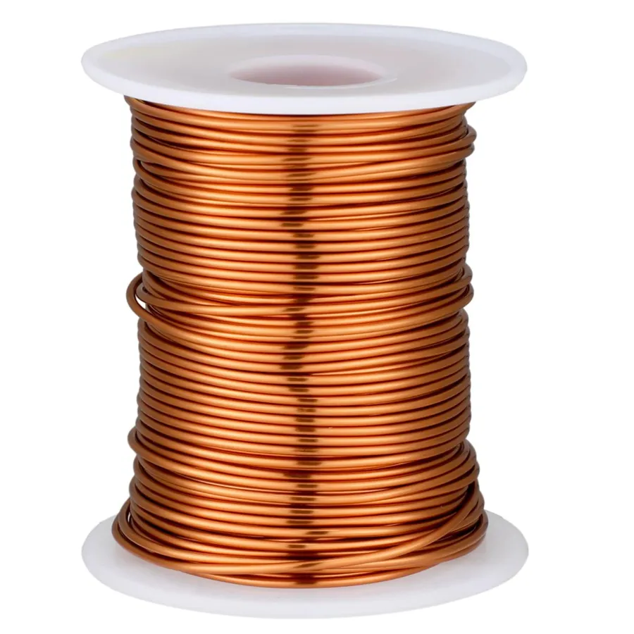
Electrical conductors are materials that facilitate the flow of electric current with minimal resistance. In a simple electric circuit, they provide the necessary pathways for electrons to move from the power source, through the load, and back to the source, thus completing the circuit. The most common form of conductor in basic circuits is wire.
| Material | Conductivity | Common Application | Advantages | Disadvantages |
|---|---|---|---|---|
| Copper | Very High | Electrical wiring, electronic components | Excellent conductivity, malleable, relatively inexpensive | Can oxidize (tarnish) over time |
| Aluminum | High | Overhead power lines, some internal wiring | Lightweight, good conductivity, corrosion-resistant | Less conductive than copper, more prone to breakage |
| Silver | Highest | High-end electronics, specialized applications | Excellent conductivity, high corrosion resistance | Expensive |
| Gold | High | Connector contacts, electronic components | Excellent conductivity, highly corrosion-resistant | Very expensive |
| Iron | Moderate | Some types of resistors and electromagnets | Relatively strong and inexpensive | Poor conductivity compared to copper, prone to rust |
The conductivity of a material is determined by its atomic structure. Conductors have loosely bound electrons in their outer shells, allowing these electrons to move freely with the application of an electric field. This movement of electrons constitutes the electric current. While various materials can conduct electricity, the choice of conductor in a simple electric circuit is largely dependent on cost, ease of use, and required conductivity. For example, while silver is the most conductive material, its high cost makes copper the most popular choice in most basic electronic applications.
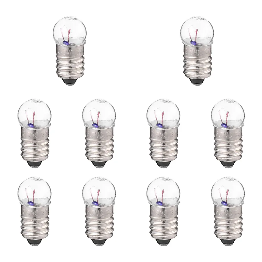
In a simple electric circuit, the 'load' is the component that converts electrical energy into another form of energy, performing a specific function. This transformation is the core purpose of the circuit beyond merely establishing current flow. Common examples include light bulbs converting electrical energy to light and heat, and resistors converting electrical energy to heat.
The load is integral to the functionality of the circuit. Without a load, the circuit would be a short circuit, resulting in excessive current and potential damage to the power source. The characteristics of the load, such as its resistance, determine the current flowing through the circuit, as defined by Ohm's law (V=IR). Understanding how various loads behave is essential for effective circuit design and operation.
| Load Type | Function | Energy Conversion | Common Applications |
|---|---|---|---|
| Light Bulb | Provides illumination | Electrical to Light and Heat | Lighting, indicators |
| Resistor | Limits current flow and generates heat | Electrical to Heat | Circuit protection, heating elements |
| Motor | Converts electrical energy into mechanical motion | Electrical to Mechanical | Fans, pumps, appliances |
| LED (Light Emitting Diode) | Provides illumination with high efficiency | Electrical to Light | Displays, indicators |
| Heater | Generates heat | Electrical to Heat | Heating appliances |
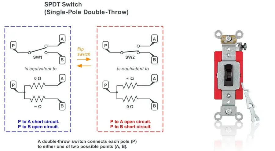
A switch is a fundamental component in an electrical circuit, acting as a gatekeeper that controls the flow of electricity. By opening or closing the circuit path, a switch allows the user to selectively activate or deactivate the circuit's operation.
Switches are designed to create a break in the conductive path of a circuit to stop the flow of current or to complete the circuit to allow current flow. This control is crucial for powering devices on and off and for managing the functionality of electrical systems.
| Switch Type | Description | Application |
|---|---|---|
| SPST (Single-Pole Single-Throw) | A simple on/off switch. Two terminals either connect or disconnect the circuit. | Controlling a light bulb or powering a single component. |
| SPDT (Single-Pole Double-Throw) | A switch that can connect one terminal to one of two others. | Used to redirect current between two different circuit paths or loads. |
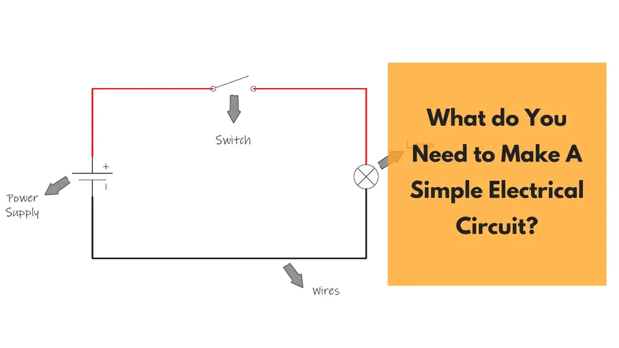
Constructing a basic electric circuit is a fundamental exercise in understanding electrical principles. This section provides a detailed, step-by-step guide to assembling a simple circuit, incorporating safety precautions and hands-on project guidance.
Before you begin, ensure you have the following materials: * A battery (e.g., 1.5V or 9V). * A battery holder (if needed). * Insulated copper wires. * A small light bulb or LED. * A light bulb holder or appropriate LED connector. * An optional switch. * Safety glasses
Safety Precautions: * Always use appropriate voltage and current levels for your components. * Ensure all connections are insulated to prevent accidental short circuits. * Never work with mains electricity without proper training and supervision. * Do not touch bare wires while the circuit is powered. * Wear safety glasses to protect your eyes.
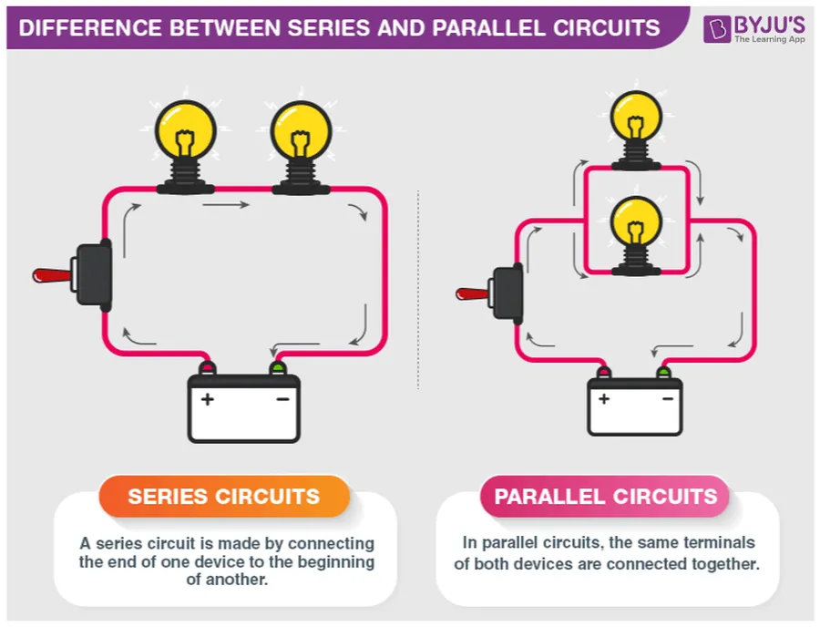
Understanding the distinction between series and parallel circuits is fundamental in electrical engineering. These two configurations dictate how current flows and voltage is distributed within a circuit, significantly impacting their applications and behavior. This section will provide a clear comparison, highlighting key differences in current flow, voltage distribution, and practical applications.
| Characteristic | Series Circuit | Parallel Circuit |
|---|---|---|
| Current Flow | Same current through all components | Current divides between branches |
| Voltage Distribution | Voltage divides across components | Same voltage across all components |
| Total Resistance | Sum of individual resistances | Reciprocal of the sum of the reciprocals of individual resistances |
| Component Failure | One component failure breaks entire circuit | One component failure does not break entire circuit |
| Applications | Christmas lights (older models), simple sensor circuits | Household wiring, car electrical systems |
In a **series circuit**, components are connected end-to-end, forming a single path for current. As a result, the current remains the same throughout the circuit, while the voltage is distributed across each component. The total resistance in a series circuit is the sum of individual resistances. A key disadvantage is that if one component fails, the entire circuit is broken. In contrast, a **parallel circuit** provides multiple paths for current. The voltage remains the same across all components, while the current divides across different branches. The total resistance of a parallel circuit is lower than the smallest individual resistance. A significant advantage is that failure of one component does not affect the operation of others in the circuit.
Circuit diagrams, also known as schematic diagrams, are fundamental tools for representing electrical circuits using standard symbols. These diagrams provide a simplified, universal language that allows engineers and hobbyists alike to understand and communicate circuit designs effectively, independent of the physical layout of components.
Understanding these symbols is crucial for both creating and interpreting circuit diagrams. Each symbol represents a specific component, like a resistor, capacitor, or a battery, allowing for quick identification and comprehension of a circuit’s function.
| Symbol | Component | Description |
|---|---|---|
| A straight line | Conductor (Wire) | Represents the path through which electricity flows. Connects components. |
| A long line and a short line, often marked with + and - | Battery (DC Power Supply) | Provides the voltage required for current to flow in the circuit. The longer line indicates the positive terminal. |
| A circle with a 'x' or a zigzag line | Load (Resistor or Light Bulb) | Indicates a component that converts electrical energy into another form, such as heat or light, or resists the flow of current. |
| Two short parallel lines | Capacitor | Stores electrical charge. Often used to smooth out fluctuations in voltage. |
| A circle with a line going through the center | Switch | Controls the flow of current. An open switch stops current; a closed switch allows it to flow. |
| A circle with an 'A' in the middle | Ammeter | Used to measure the current flowing through a circuit and is always connected in series. |
| A circle with a 'V' in the middle | Voltmeter | Used to measure the voltage drop or potential difference across components and is always connected in parallel. |
| A circle with a diode symbol inside | Diode | Allows current to flow in one direction only. |
Drawing circuit diagrams is a fundamental skill for anyone working with electronics. It enables clear communication of circuit designs and facilitates troubleshooting. When sketching a circuit, pay attention to the connections and the correct symbols for each component. A well-drawn diagram helps to both construct and analyze electronic circuits accurately.
This section addresses common questions about simple electrical circuits, providing concise answers to clarify key concepts. We've compiled these questions based on typical user inquiries and fundamental circuit principles.
Successfully constructing a simple electric circuit is a fundamental step in understanding electricity. However, encountering issues is common, making troubleshooting essential. This section focuses on diagnosing common problems like open circuits and short circuits, and introduces the use of a multimeter for basic circuit testing, enabling a practical and systematic approach to resolving these issues.
A simple electric circuit, though basic, is the foundation of all electrical devices. Understanding its components and how they work together empowers you to grasp more complex circuits and technologies. Just as a complete circuit is needed for electricity to flow, continued exploration of these concepts will illuminate your path in understanding the world of electronics. Remember, starting with these simple principles will empower you to explore further. Happy building!

