Choosing the Right PCB Circuit Maker: A Comprehensive Guide
In today's tech-driven world, printed circuit boards (PCBs) are the backbone of almost every electronic device. Whether you're a seasoned engineer or a hobbyist, choosing the right PCB circuit maker software is essential for bringing your designs to life. This article will explore the best free and commercial options, examining the features, pros, and cons of different platforms. We’ll navigate through leading PCB design solutions, from Altium's CircuitMaker to EasyEDA and KiCad, providing you with the knowledge to make an informed decision.
Understanding Your PCB Design Needs
Selecting the appropriate PCB circuit maker hinges on a clear understanding of your project's specific requirements. This crucial initial step involves assessing multiple factors that will directly influence your software choice and overall design process, ensuring efficient and effective PCB creation.
- Project Complexity
Distinguish between simple, single-layer hobby projects and complex, multi-layered professional designs, as this dictates the software's necessary capabilities. - Number of Layers
Determine the number of layers required for your PCB, as some software may have limitations or varying support for multi-layer designs. - Budget Constraints
Evaluate your financial resources, considering whether a free option suffices or if investing in a paid professional software is necessary, balancing features with affordability. - Design Complexity
Assess the complexity of your design needs, including the need for advanced routing algorithms, component libraries, and simulation tools.
CircuitMaker: Free and Powerful
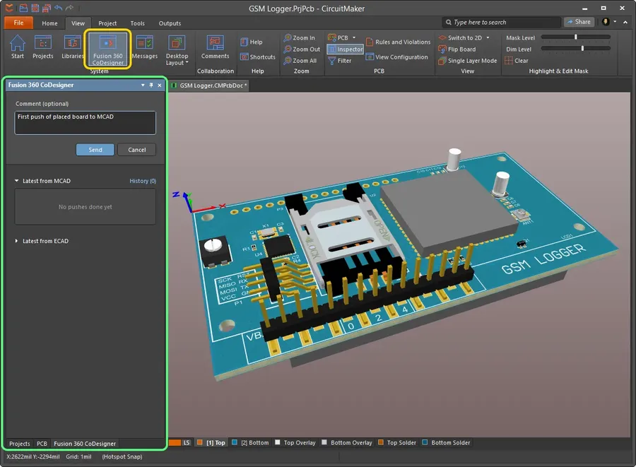
CircuitMaker, developed by Altium, stands out as a robust, free PCB design software tailored for open-source hardware enthusiasts. It offers advanced functionalities such as multi-layer support and unrestricted PCB dimensions while fostering a collaborative design environment, however, it's important to note that its user interface may present a steep learning curve for beginners.
- Core Features
CircuitMaker boasts multi-layer support, allowing for complex PCB designs, and places no limitations on board dimensions, a significant advantage for intricate projects. - Pricing
The software is completely free, making it accessible to hobbyists and professionals alike. This zero-cost model is a major draw for users seeking powerful capabilities without financial barriers. - Strengths
Its key strengths lie in its powerful feature set, collaborative platform, and the absence of restrictions typical in free software. Its integration with Altium's ecosystem also provides access to a wealth of resources. - Ideal Users
CircuitMaker is ideally suited for open-source hardware developers, experienced designers, and those working on complex PCB projects. While it's free, beginners may find its interface and advanced features initially daunting.
EasyEDA: Browser-Based Simplicity
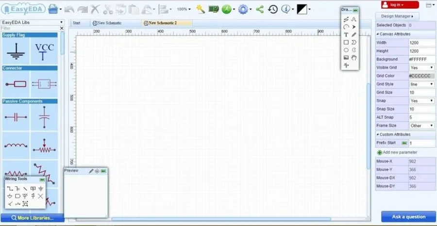
EasyEDA distinguishes itself as a free, browser-based PCB design tool, prioritizing ease of use and accessibility, making it an excellent choice for beginners seeking a straightforward design experience. Its notable features include online circuit simulation, comprehensive component libraries, and direct integration with PCB fabrication services, streamlining the entire design and production process.
- Ease of Use
The intuitive interface of EasyEDA is designed for quick learning, with drag-and-drop functionality and simplified toolsets for schematic capture and PCB layout. This reduces the initial learning curve, allowing users to focus on design rather than software operation. - Online Accessibility
Being a web-based tool, EasyEDA allows users to access their projects from any computer with an internet connection, eliminating the need for software installation and enabling seamless collaboration. This cloud-based approach also facilitates easy sharing and version control of PCB designs. - Integrated Simulation
EasyEDA's online circuit simulation feature permits real-time testing of design functionality before physical fabrication, which significantly reduces errors and design iterations. This simulation capability supports both basic analog and digital simulations and uses industry standard simulation engines. - Extensive Component Libraries
The tool includes a wide range of pre-built component libraries that speed up the design process by providing ready-to-use electronic parts with accurate footprints and models. This access to a variety of components reduces the need for custom model creation. - Direct PCB Fabrication
EasyEDA simplifies the transition from design to fabrication with direct integration to PCB manufacturing services, allowing for a streamlined workflow. This integration reduces manual steps and speeds up the prototyping process.
| Feature | Description | Advantage | Limitation |
|---|---|---|---|
| Web-Based Access | Runs directly in a web browser. | No software installation required, accessible anywhere with internet. | Dependent on internet connection; performance may vary based on connection speed. |
| Ease of Use | Intuitive drag-and-drop interface and simplified toolsets. | Reduces learning curve, suitable for beginners. | May lack some advanced features available in desktop applications. |
| Online Circuit Simulation | Integrated SPICE-based simulator. | Allows testing designs before fabrication. | Simulation may not be as detailed as with dedicated software tools. |
| Component Libraries | Extensive library of pre-built components. | Speeds up the design process, reduces manual model creation. | Library may not include every possible component. |
| Integrated Fabrication | Direct link to PCB manufacturing services. | Streamlines the design to fabrication process. | May be limited to specific fabrication partners. |
KiCad: Open-Source Powerhouse
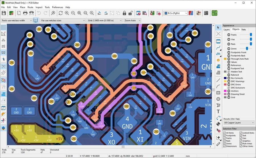
KiCad is a robust, free, and open-source Electronic Design Automation (EDA) suite, offering a complete environment for schematic capture, PCB layout, and 3D visualization. Its professional-grade capabilities make it suitable for a wide spectrum of projects, from simple to highly complex designs, without the burden of licensing fees. KiCad's platform independence, coupled with a strong community, further cements its position as a leading open-source solution for PCB design.
- Advanced Features
KiCad boasts a wide array of advanced features, including multi-layer support, differential pair routing, and interactive routing tools, allowing for the design of complex PCBs. - No Cost Access
Being completely free and open-source, KiCad eliminates financial barriers to PCB design, making it accessible to hobbyists, students, and professionals alike. - Cross-Platform Compatibility
KiCad is compatible with Windows, macOS, and Linux, offering consistent functionality across different operating systems. - Strong Community Support
KiCad's vibrant community provides extensive documentation, tutorials, and user forums, facilitating collaboration and troubleshooting.
| Feature | Description |
|---|---|
| Schematic Capture | Creation and editing of electronic schematics using a comprehensive component library. |
| PCB Layout | Tools for placing components, routing traces, and defining board layers. |
| 3D Viewer | Visualization of the PCB in a three-dimensional environment for better design validation. |
| Gerber File Generation | Generation of industry-standard Gerber files required for PCB manufacturing. |
| Scripting and Customization | Ability to extend functionality through Python scripting and custom plugins. |
Other Noteworthy PCB Circuit Maker Options
While CircuitMaker, EasyEDA, and KiCad are popular choices, the landscape of PCB design software extends to various other tools, each catering to specific user needs and project complexities. These alternatives range from professional, paid software suites like Altium Designer to simpler, free tools and online platforms, offering a spectrum of capabilities and cost options.
| Software | Cost | Target User | Key Strengths | Main Drawbacks |
|---|---|---|---|---|
| Altium Designer | Paid (Subscription) | Professional Engineers | Industry-leading features, extensive component library, comprehensive design rule checks | High cost, steep learning curve |
| Eagle (Autodesk) | Free version available, Paid for advanced features | Hobbyists and Professional Engineers | Good balance of features and price, widely used | Can be complex for beginners |
| DipTrace | Paid (One-time Purchase) | Small Businesses and Professionals | Intuitive interface, comprehensive 3D modeling | Less extensive community support |
| DesignSpark PCB | Free | Hobbyists and Small Businesses | Easy to learn, integration with component supplier RS Components | Less advanced features compared to paid options |
| FreePCB | Free | Hobbyists | Simple and lightweight | Limited features, basic functionality |
| Upverter | Free and Paid Options | Collaborative Teams | Browser-based platform, real-time collaboration capabilities | Can be dependent on internet connection |
The selection of a PCB circuit maker ultimately depends on your project's unique needs, budget, and familiarity with design tools. Beginners might benefit from simpler, free tools like DesignSpark PCB or FreePCB. Those with more complex project requirements may consider Eagle, Altium Designer or DipTrace. Collaborative teams will want to consider the browser based tools like Upverter. Evaluating the pros and cons of each software is crucial to maximizing design efficiency and achieving optimal results.
PCB Design Workflow: Step-by-Step
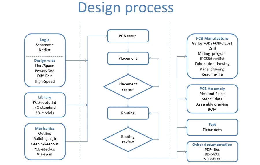
A structured workflow is crucial for efficient PCB design, regardless of the specific software used. This systematic approach ensures a well-organized design process, minimizing errors and optimizing the final product. The typical PCB design workflow involves several key stages, from initial concept to final manufacturing output. Understanding these steps is fundamental to successfully transforming an electronic idea into a physical circuit board.
- Schematic Design
The initial phase involves creating a schematic diagram, which is a symbolic representation of the electronic circuit. This stage includes placing components and connecting them with wires to define the electrical connections within the circuit. Schematic capture tools in PCB design software facilitate this process, allowing designers to create the foundation of their circuit. - Component Selection
Following the schematic design, the designer chooses specific electronic components. The selection includes specifying the component's type (e.g., resistor, capacitor, IC), package (physical size and shape), and value or specification. This step ensures that the parts used in the design are compatible and suitable for the intended application. Accurate component selection is crucial for proper circuit functionality. - Board Layout
With the schematic complete and components selected, the next step is arranging components and traces on the physical board. This involves placing components within the physical boundaries of the PCB and routing the electrical connections between them using conductive traces. This step requires careful consideration of physical constraints, signal integrity, and thermal management. The goal is to produce an effective and manufacturable design. PCB design software tools offer various features, such as automated routing, to facilitate this process. - Design Rule Checks (DRC)
Once the board layout is complete, design rule checks are performed to ensure that the design adheres to industry and manufacturer standards. These checks detect issues like trace width violations, component overlaps, and other potential manufacturing problems. Passing DRC is essential for ensuring the manufacturability of the design. Design rule parameters are often specified in the software and can be customized per project. Thorough checks ensure that the board will function correctly once fabricated. - Gerber File Generation
The final step involves generating Gerber files, which are standard vector files used in the manufacturing of PCBs. These files define all the layers of the PCB, such as copper traces, solder mask, and silkscreen. Manufacturers rely on Gerber files to fabricate the PCB correctly. The final generated files contain comprehensive information about all design aspects, enabling PCB fabricators to produce the physical circuit boards accurately based on the created design.
Frequently Asked Questions About PCB Circuit Makers
Selecting the right PCB circuit maker can be daunting, especially with the variety of options available. This section addresses common queries to provide clarity and actionable insights, ensuring you make an informed decision aligned with your project needs.
- How do you create a PCB circuit design?
The PCB design process involves several key steps. First, you need to define your circuit's functionality and create a schematic diagram. Then, you translate that schematic into a physical layout on a PCB, placing components and routing traces. Finally, you generate Gerber files, which are standard manufacturing files used by PCB fabrication houses to produce the actual board. Different software tools may automate or streamline parts of the workflow, but these are the core stages. - What is the cost of CircuitMaker software?
CircuitMaker is a free PCB design software offered by Altium, so there are no licensing costs associated with using it. This makes it particularly attractive for hobbyists, educators, and smaller-scale open-source hardware projects. While it is free to use, keep in mind there may be costs associated with PCB fabrication. - What do you call a person who designs circuit boards?
Professionals who design circuit boards are commonly known as PCB designers, layout engineers, or electronics engineers, depending on their specific role and company structure. These individuals possess a blend of engineering knowledge and practical skills to translate functional requirements into physical electronic hardware. - How do you use CircuitMaker to create a PCB design?
To design a PCB in CircuitMaker, you generally follow a structured workflow. Start by creating a schematic diagram of your circuit, then convert it into a PCB layout where components are placed and connected using traces. CircuitMaker also includes features for design rule checks to verify the integrity of your board. Once the layout is finalized, you can generate Gerber files for fabrication. The user interface and features offered make this process robust and relatively efficient. - What are the key considerations when selecting PCB design software?
When selecting PCB design software, consider factors like the project complexity, your level of expertise, and your budget. Evaluate user interface, capabilities (e.g. multi-layer support, simulation), and integration with fabrication services. Also, consider the available community support and online resources, which can greatly ease your learning curve and design process. - What kind of support is available for PCB design software?
Support for PCB design software varies, but often includes comprehensive documentation, tutorials, user forums, and technical support directly from the software provider. Many open-source tools also have active user communities that provide robust assistance. The level of support can be a critical factor, especially if you're encountering complex design challenges. - What is the learning curve of different PCB design software?
The learning curve varies significantly among PCB design software. Tools like EasyEDA are often considered more beginner-friendly due to their intuitive user interface. Other tools such as CircuitMaker and KiCad can be more complex, necessitating a greater initial time investment. Your past experience with design or software can greatly influence your learning speed and progress.
Comparative Analysis: Key Features and Pricing
This section provides a direct comparison of key features and pricing models across several popular PCB circuit maker options, namely CircuitMaker, EasyEDA, and KiCad. This analysis is structured in a table format to allow for quick identification of the solution that best suits your specific project needs. The parameters considered for this comparison include cost, learning curve, layer support, online/offline design capabilities, and community support.
| Feature | CircuitMaker | EasyEDA | KiCad |
|---|---|---|---|
| Cost | Free | Free | Free |
| Learning Curve | Moderate to High | Low to Moderate | Moderate |
| Layer Support | Unlimited | Limited (Free Tier) | Unlimited |
| Online/Offline Design | Offline | Primarily Online | Offline |
| Community Support | Good, but more targeted at open-source hardware enthusiasts | Active online forum with direct support | Large and active open-source community |
Tips for Choosing the Right PCB Circuit Maker
Selecting the appropriate PCB circuit maker is a crucial step in your electronics design journey. This section provides practical advice tailored for beginners to navigate this decision effectively, ensuring your project goals are met with the right software.
- Define Your Project Scope
Clearly identify your project's complexity. A simple, single-layer hobby project has very different needs than a complex, multi-layer professional design. Understanding the scale and requirements will narrow down suitable software options. - Assess Your Skill Level
Consider your current familiarity with PCB design. Beginners might prefer more intuitive, user-friendly interfaces (e.g., EasyEDA), while experienced users may appreciate the power of more feature-rich software like KiCad or CircuitMaker. Don't overestimate your proficiency; choosing an overly complex tool can lead to frustration. - Evaluate Necessary Features
List essential features such as the number of board layers, component library needs, simulation capabilities, and collaboration tools that are relevant to your project. Prioritize functions that are critical for successful project completion. Software boasting unnecessary features might complicate the learning curve. - Consider Cost Implications
While several free options like CircuitMaker, EasyEDA, and KiCad are available, paid software may offer additional advantages like specialized libraries or support. Carefully assess your budget and weigh the benefits of premium software versus the robust capabilities of free alternatives. - Prioritize Learning Resources
Check the availability of tutorials, documentation, and community support for your chosen software. A comprehensive support network can be invaluable, particularly when starting out. A strong community can accelerate the learning process and provide ready solutions to common issues. - Plan for Future Scalability
Consider whether your choice will support more complex projects as your skills evolve. Choosing a versatile tool, even if you start with simpler projects, reduces the need to switch platforms as your experience grows.
Avoiding common errors is also crucial. Ensure your software choice is compatible with your operating system and that you carefully review design rule checks before fabrication. A meticulous approach early in the design phase mitigates errors and reduces costly revisions later on.
Choosing the right PCB circuit maker is crucial for bringing your electronic projects to life. This article has provided an overview of leading free and commercial options, including CircuitMaker, EasyEDA, and KiCad, to help you select the best fit for your needs. Remember to consider your project's complexity, your budget, and your preferred workflow. The right software, coupled with a strong understanding of the PCB design process, will empower you to create innovative and effective electronic circuits. With the tools mentioned, anyone from beginner hobbyists to professional engineers can successfully create a printed circuit board design.