Choosing the Right Rigid-Flex PCB Manufacturer: A Comprehensive Guide
In today’s rapidly evolving technological landscape, rigid-flex PCBs are becoming increasingly essential in many applications, offering a unique blend of flexibility and stability. Selecting the right rigid flex pcb manufacturer is a critical decision that can significantly impact the performance and reliability of your product. This guide will help you make an informed choice, providing insights into what to look for in a manufacturer and highlighting key factors for success in your project, from prototype to mass production.
Understanding Rigid-Flex PCB Technology
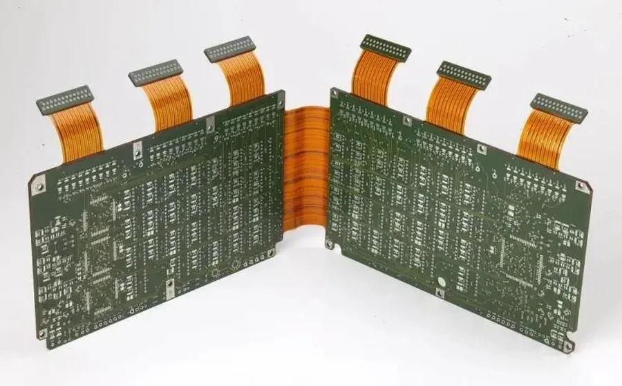
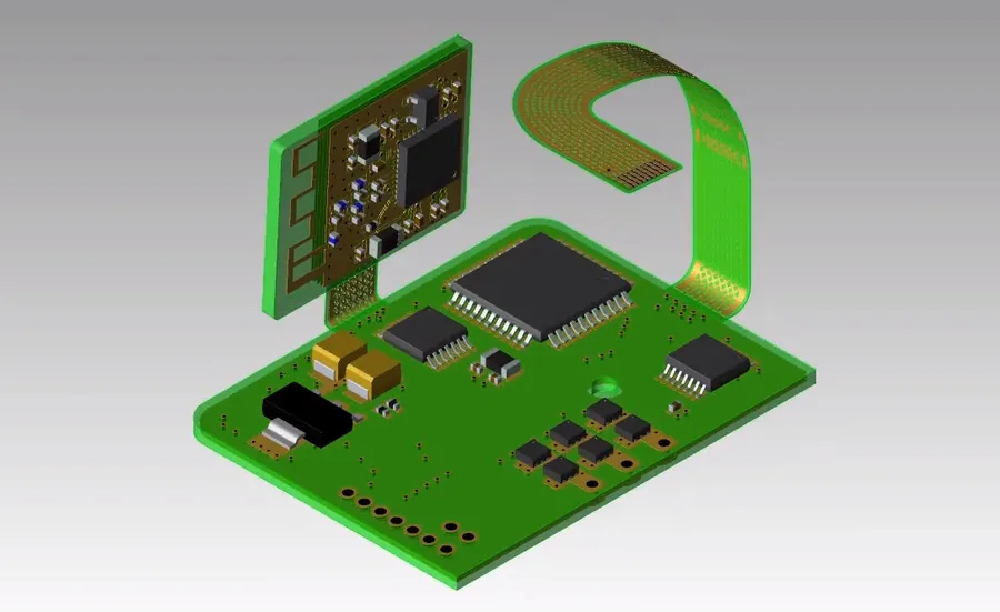
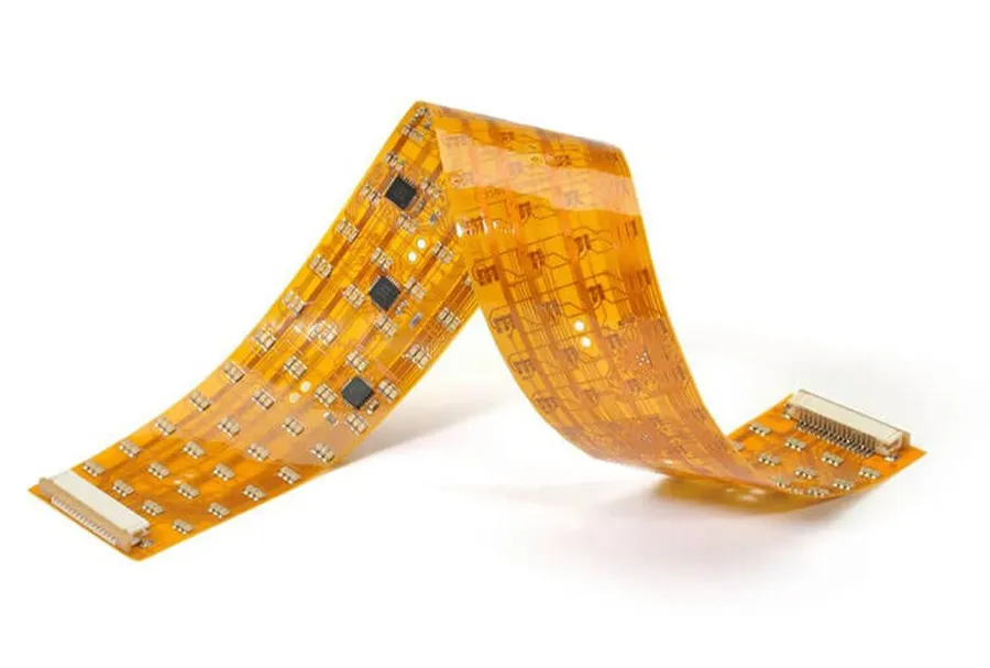
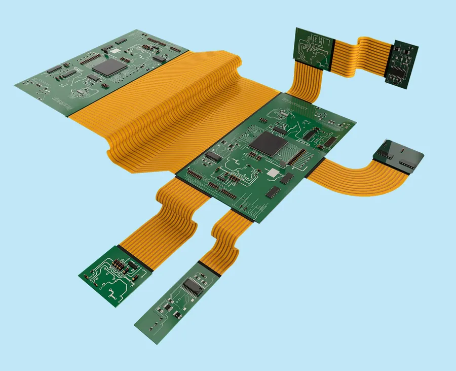
Rigid-flex PCB technology represents a sophisticated approach to circuit board design, integrating the strengths of both rigid and flexible substrates into a single, interconnected structure. This hybrid approach enables designers to create electronic devices that require both structural rigidity for component mounting and flexible sections for dynamic interconnections or complex geometries, offering significant advantages in terms of space utilization, weight reduction, and overall system reliability. Understanding the nuances of this technology is paramount before engaging a rigid flex PCB manufacturer.
| Feature | Rigid PCB | Flexible PCB | Rigid-Flex PCB |
|---|---|---|---|
| Structure | Solid, inflexible | Flexible, bendable | Combination of rigid and flexible areas |
| Applications | General electronics | Dynamic interconnects, wearables | Complex devices, aerospace, medical |
| Flexibility | None | High | Partial |
| Interconnect | Discrete connectors or wires | Flex circuits | Integrated flex sections |
| Space efficiency | Moderate | High | Very high |
| Complexity | Low to moderate | Moderate | High |
- Advantages of Rigid-Flex PCBs
Reduced size and weight, improved reliability due to fewer interconnects, enhanced design flexibility, and improved signal integrity. - Common Applications
Aerospace systems, medical devices, automotive electronics, consumer electronics (smartphones, wearables), and industrial equipment.
Key Factors to Consider When Choosing a Rigid-Flex PCB Manufacturer
Selecting the right rigid-flex PCB manufacturer is crucial for ensuring the quality, reliability, and performance of your final product. This decision hinges on several key factors beyond just cost, including the manufacturer's experience, certifications, technological capabilities, and capacity to meet your specific design requirements.
- Manufacturing Experience and Expertise
A manufacturer's experience directly impacts the quality and reliability of the PCBs produced. Look for a manufacturer with a proven track record in rigid-flex PCB fabrication, including demonstrated experience with complex, multilayer designs and tight tolerances. Years in the industry, specific projects completed, and customer testimonials can serve as indicators of expertise. - Certifications and Industry Standards
Certifications like ISO 9001:2015 (Quality Management System) and ISO 13485:2016 (Medical Devices) demonstrate a manufacturer's adherence to quality standards. These certifications provide assurance that the manufacturer has established processes and controls in place to consistently deliver high-quality products. Compliance with industry-specific standards, such as IPC standards, is also a key consideration. - Technological Capabilities
Assess whether the manufacturer has the necessary equipment and process capabilities to handle your specific design. This includes advanced drilling technology, laser direct imaging (LDI), high-precision etching, and automated optical inspection (AOI). Specifically, consider their ability to handle: Multilayer builds, varied material combinations, specific via types (blind and buried), and microvias. - Design for Manufacturing (DFM) Support
A good manufacturer should provide DFM support, identifying potential design issues that may cause manufacturing challenges and offering solutions. Early DFM analysis minimizes revisions, reduces costs and speeds up production. Look for a manufacturer with the ability to do pre-production reviews. - Material Handling Expertise
Rigid-flex PCBs use a range of materials including flexible polyimides and rigid FR-4. The manufacturer should have experience with different material combinations and be able to advise on the best materials for your application based on required flexibility, temperature resistance, and electrical characteristics. - Panel Size and Layer Handling
Ensure the manufacturer can accommodate your specific panel sizes and layer counts. Their equipment should be able to handle the required dimensions, including non-standard shapes and thicknesses. A large enough panel size can provide efficiency in manufacturing, reducing overall cost. - Prototyping and Quick-Turn Capabilities
If you need rapid prototyping or smaller runs, inquire about the manufacturer's quick-turn capabilities. The manufacturer should be able to quickly produce a prototype that mirrors the final production board.
Material Selection for Rigid-Flex PCBs
The selection of appropriate materials is paramount in rigid-flex PCB design, directly impacting the final product's performance, flexibility, durability, and overall reliability. This decision must be aligned with the intended application and environmental conditions.
Key material considerations include the substrate, coverlay, and adhesive. Different materials will exhibit varying degrees of flexibility, temperature resistance, and electrical properties, necessitating a thorough understanding of each material's characteristics.
| Material | Description | Key Characteristics | Typical Applications |
|---|---|---|---|
| Polyimide (PI) | A high-performance polymer known for its excellent thermal and mechanical properties. | High temperature resistance, excellent flexibility, chemical resistance, stable dielectric properties. | Aerospace, medical devices, high-reliability electronics |
| FR-4 | A composite material composed of woven fiberglass cloth with an epoxy resin binder, most commonly used for rigid PCB sections. | Good electrical insulation, relatively inexpensive, good mechanical strength, rigid. | General-purpose electronics, consumer electronics |
| Polyester (PET) | A thermoplastic polymer known for its tensile strength and chemical resistance. | Good tensile strength, chemical resistance, low cost, limited flexibility at high temperatures. | Low-cost flexible electronics, keyboards, membrane switches |
| Adhesives | Used to bond different layers together. Acrylic and epoxy adhesives are common. | Adhesion strength, temperature resistance, flexibility, chemical compatibility. Should be chosen based on the materials being bonded and the operating environment | Bonding layers in rigid-flex boards |
| Coverlay Materials | Flexible material used to protect outer layers of the flexible circuit (often Polyimide with adhesive) | Flexibility, chemical resistance, dielectric properties, thermal stability, protects against physical damage and environmental factors | Protecting external layers of flex circuits |
Design Considerations for Rigid-Flex PCBs
Effective design of rigid-flex PCBs is paramount to ensure both manufacturability and optimal performance. This involves careful consideration of the layer stack-up, trace routing, and bend radius limitations, which directly influence the final product's reliability and functionality.
- Layer Stack-Up Design
The arrangement of rigid and flexible layers in a rigid-flex PCB is crucial. It impacts the overall thickness, flexibility, and signal integrity of the board. A well-defined layer stack-up should consider the required impedance control, mechanical stress, and thermal management. - Trace Routing Strategies
Routing traces in rigid-flex PCBs requires careful planning, particularly in the transition areas between rigid and flexible sections. Sharp angles should be avoided in the flexible sections to prevent stress concentration and potential trace cracking. It’s best to use gradual curves for routing in flex areas. - Bend Radius Requirements
The bend radius is the smallest curvature a flexible part of the PCB can sustain without damage. Exceeding the minimum bend radius will result in damage to the circuit. This depends on material thickness and the number of layers in the flex area, with tighter bends possible in single or double-sided flexible layers. Refer to your manufacturer's datasheet for specific design rules. - Transition Zones
The transition between the rigid and flexible areas requires special attention in design. Smooth transitions are crucial to prevent stress points and fatigue in the copper and flex materials during flexing. A good rule of thumb is to increase the distance between copper routing and the edges of flex. - Via Placement
Proper via placement is crucial, particularly in the transition areas. Vias should be placed in the rigid area or far from the bend point, if vias need to be placed in the flex area, it is suggested that use of flexible filled via that help with the connection during flexing.
| Design Element | Consideration | Impact |
|---|---|---|
| Layer Stack-Up | Material selection, number of layers, and arrangement | Impedance, flexibility, cost, and signal integrity. |
| Trace Routing | Routing path in flex and rigid areas | Signal performance, stress reduction and manufacturability |
| Bend Radius | Minimum bend radius in flexible area | Mechanical reliability and lifetime |
| Transition Zones | Smooth transition between flex and rigid areas | Mechanical and electrical reliability |
| Via Placement | Via placement in relation to bending areas | Mechanical and electrical reliability |
Manufacturing Processes and Capabilities
The selection of a suitable rigid-flex PCB manufacturer hinges significantly on their manufacturing processes and technological capabilities. These factors dictate the complexity of designs they can handle, the quality of the final product, and the speed at which they can deliver. This section delves into the critical manufacturing aspects to consider when choosing a partner.
- Lamination
Lamination is the core process of bonding the rigid and flexible layers together using heat and pressure, critical to creating a cohesive rigid-flex structure. The manufacturer's expertise in this process will directly impact the reliability and durability of your board. Look for manufacturers that can maintain accurate layer alignment and consistent bonding strength. - Drilling
High-precision drilling is paramount for creating vias and component mounting holes. Rigid-flex boards often involve complex drill patterns across different materials with varying thicknesses. A manufacturer equipped with advanced drilling technology, such as laser drilling, is essential to achieve tight tolerances and avoid damage to the flexible substrates. - Etching
Etching is used to define the conductive patterns on both rigid and flexible layers. Precise control over the etching process is required to achieve the desired trace widths, spacing, and electrical performance characteristics for the rigid flex PCB. A manufacturer with fine-line etching capabilities will be able to produce higher density interconnects. - Routing and Cutting
After the basic layers are made, the manufacturer will need to route and cut out the final board shape. Accuracy is essential to ensure that the final board fits into the intended enclosure.
| Capability | Description | Importance |
|---|---|---|
| Multilayer Capability | Ability to manufacture boards with multiple layers of rigid and flexible materials. | Essential for complex designs requiring increased routing density. |
| Panel Size Handling | Capability to handle different panel sizes to meet various project demands. | Ensures efficiency and reduces wastage by matching manufacturing processes with project needs. |
| Quick-Turn Prototyping | Ability to produce prototypes rapidly. | Accelerates design verification and time-to-market. |
| Fine Line Etching | Ability to produce very thin traces and spacing. | Critical for high-density designs, miniaturization. |
| Laser Drilling | Capability to drill extremely small and precise holes. | Necessary for fine pitch components and complex interconnects |
Quality Control and Testing for Rigid-Flex PCBs
Rigorous quality control and testing are paramount in the manufacturing of rigid-flex PCBs, ensuring the final product's reliability and functionality. These processes identify defects early, preventing costly failures down the line, and ultimately confirm that the manufactured PCBs meet the required design specifications and performance standards. A robust quality control process is a critical factor in selecting a rigid flex pcb manufacturer.
- In-Circuit Testing (ICT)
ICT uses electrical probes to test the connectivity and integrity of components after they are assembled onto the rigid-flex PCB. This verifies correct placement and soldering of components. Common ICT tests include shorts, opens, and resistance checks, which ensures the circuit functions as designed and reduces chances of system failure after deployment. - Automated Optical Inspection (AOI)
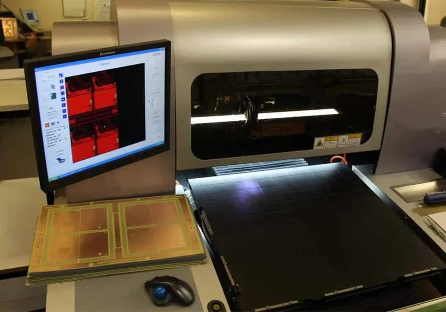
AOI employs high-resolution cameras to visually inspect the PCB for defects such as misaligned components, solder bridges, and missing parts. The visual inspection of the board can reveal manufacturing defects that other methods might miss, including surface scratches or etching anomalies. AOI is a key step to prevent flawed PCBs from advancing in the manufacturing process. - X-Ray Inspection
X-ray inspection is used to examine internal layers and solder joints on multi-layer rigid-flex PCBs that are not visible to optical inspection. This method can identify voids, misalignment, and other flaws that can affect the performance or reliability of the PCB. It’s especially crucial for complex boards with many layers or high-density interconnects. - Functional Testing
Functional testing involves applying operational parameters to the assembled rigid-flex PCB to determine if it performs its intended function correctly. This testing includes simulation of the end-use environment and conditions to determine the real-world performance. Functional testing is the ultimate step to verify the board performs reliably in all intended use conditions. - Reliability Testing
Reliability testing goes beyond basic functional testing to assess a PCB's long-term performance under stress. This involves environmental testing, such as thermal shock, vibration, and humidity exposure, that will simulate the environment that the board will experience in real-world use. These tests identify potential weaknesses, improving the long term reliability of the product.
| Test Type | Purpose | Detection Focus |
|---|---|---|
| In-Circuit Testing (ICT) | Verifies component placement and electrical connections. | Shorts, opens, incorrect component values. |
| Automated Optical Inspection (AOI) | Visual inspection of solder joints and components. | Misaligned components, solder bridges, missing parts. |
| X-Ray Inspection | Examines internal layers and solder joints. | Voids, misalignment in internal connections. |
| Functional Testing | Verifies the PCB’s performance in its intended use. | Performance and functionality under operational conditions. |
| Reliability Testing | Assesses long-term durability under various conditions. | Performance under thermal, mechanical, and environmental stress. |
Cost Considerations and Budget Planning for Rigid-Flex PCBs
Effective cost management in rigid-flex PCB manufacturing involves a thorough understanding of various influencing factors and strategic planning. By carefully evaluating material selection, design complexity, and production volume, significant cost optimization can be achieved without compromising the required performance and reliability of the final product. Comparing quotations from multiple rigid-flex PCB manufacturers is a crucial step in securing the best value.
| Cost Factor | Description | Optimization Strategies |
|---|---|---|
| Material Costs | The price of substrates (e.g., polyimide, FR4), adhesives, and coverlays. Polyimide generally costs more than FR4. | Carefully select materials based on application requirements; explore alternative materials with similar properties but lower costs if feasible. Consider using standard thicknesses and panel sizes. |
| Design Complexity | Number of layers, via types, trace density, and intricate shapes. More complex designs lead to longer manufacturing times and potentially higher failure rates. | Simplify the design where possible, use standard via sizes and routing techniques; minimize the number of layers to reduce material and manufacturing expenses. |
| Manufacturing Volume | The quantity of PCBs to be produced. Higher volumes typically result in lower per-unit costs. | Optimize the production volume based on realistic demand forecasts, negotiate bulk discounts with manufacturers, and consider panelization for efficient production. |
| Panelization | The arrangement of multiple PCB boards on a single panel. Efficient panelization reduces material waste and increases production throughput, but may limit design freedom. | Work with the manufacturer to ensure optimum panel utilization for reduced costs, consider array design based on assembly process. |
| Testing Requirements | The extent of electrical testing, impedance testing, or other tests required. More thorough testing increases cost but ensures better reliability and quality. | Prioritize testing based on critical functionalities, and understand the cost implications of different testing protocols. |
| Turnaround Time | Expedited or quick-turn production timelines often come at a premium, so allow adequate time to minimize rush costs. | Plan production schedules in advance to avoid expediting fees; explore a phased project approach that starts with prototypes to validate design. |
Rigid-Flex PCB Assembly Frequently Asked Questions
This section addresses common questions related to rigid-flex PCB assembly, covering typical lead times, material handling, cost optimization, and other critical aspects to streamline the process.
- What are typical lead times for rigid-flex PCB assembly?
Lead times for rigid-flex PCB assembly can vary significantly based on several factors, including the complexity of the design, the availability of materials, the manufacturer's current workload, and the quantity of boards ordered. Generally, prototype assemblies may take a few days to a couple of weeks, while larger production runs can range from several weeks to a few months. Discussing lead times upfront with your rigid-flex PCB manufacturer is essential for project planning. - How should materials be handled during rigid-flex PCB assembly?
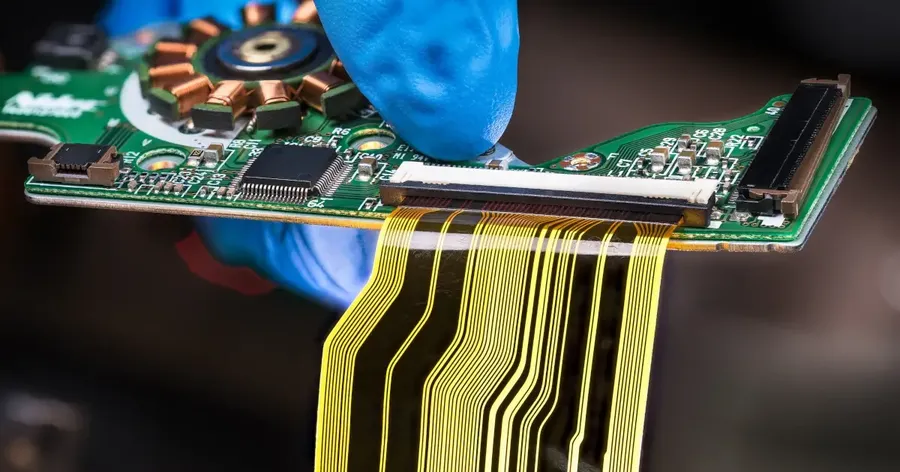
Proper material handling is crucial in rigid-flex PCB assembly due to the delicate nature of flexible materials. Careful handling is necessary to prevent damage such as tears, creases, or contamination. Manufacturers should employ specialized techniques such as using cleanroom environments, proper tooling, and anti-static measures to ensure the integrity of the materials throughout the assembly process. Automated pick-and-place systems and specialized fixtures are frequently used to minimize human contact and the risk of damage. - What are some common challenges in rigid-flex PCB assembly?
Rigid-flex PCB assembly presents several unique challenges compared to standard rigid PCB assembly. These challenges include managing the flexible portions of the board, ensuring precise alignment during component placement, preventing damage to flexible sections during soldering, and accommodating the varying thermal properties of different materials. These require careful process control and specialised equipment. Manufacturers need experience in handling these specific issues to produce high-quality assemblies. - How can assembly costs for rigid-flex PCBs be reduced?
Several strategies can help reduce rigid-flex PCB assembly costs. First, working closely with the manufacturer early in the design phase can identify cost-saving design choices such as standardizing part sizes, minimizing the number of layers and board complexity. Second, selecting materials that are suitable and readily available can reduce procurement costs. Finally, optimizing panelization to reduce waste and ordering larger quantities can also bring down per-unit costs. Exploring these cost reduction measures with your manufacturer will help you achieve the most cost-effective design. - What level of testing is typically performed during rigid-flex PCB assembly?
Rigid-flex PCB assemblies typically undergo various testing procedures to ensure functionality and reliability. These can include visual inspections for proper component placement and soldering, Automated Optical Inspection (AOI) for solder joint quality, In-Circuit Testing (ICT) for electrical verification, and functional testing to assess overall circuit performance. Specific testing requirements should be discussed with the manufacturer to ensure that the testing covers all critical aspects of the assembly. - Can a rigid-flex PCB be reworked if issues are discovered during assembly?
Reworking rigid-flex PCBs can be challenging due to the flexible substrate and the delicate nature of the components. However, it is not impossible. The ability to rework depends on the type and extent of the issues found. Minor issues such as misaligned or defective components can be addressed, however, reworking flex areas and components on flex may cause further damage to the board. It is important to discuss rework capabilities with the manufacturer to understand the limitations. Prevention through good design and process controls is always preferable. - What information should be provided to the manufacturer for a seamless assembly process?
To ensure a smooth assembly process, you should provide your rigid-flex PCB manufacturer with a comprehensive package of design data. This should include Gerber files, Bill of Materials (BOM), assembly drawings and instructions, and any specific requirements for testing or handling. Clear, complete and accurate documentation will help the manufacturer to fully understand your requirements, minimize errors, and avoid assembly delays. Consistent communication and a collaborative relationship will ensure the whole process works efficiently.
Working With a Rigid-Flex PCB Manufacturer: Best Practices
Establishing a strong working relationship with your rigid-flex PCB manufacturer is crucial for project success. This collaboration extends beyond simply placing an order; it involves clear communication, precise specifications, and effective timeline management. A well-structured partnership ensures that your project's goals are met efficiently and effectively.
- Establish Clear Communication Channels
Designate primary points of contact on both sides to streamline communication. Use written forms of communication for critical specifications and decisions to maintain a clear record. - Provide Comprehensive Project Specifications
Deliver all necessary details, including Gerber files, layer stack-up, material requirements, impedance control needs, and tolerance expectations. This clarity minimizes potential errors and ensures the manufacturer fully understands the design intent. - Define Realistic Timelines
Set realistic deadlines for each phase of the project, from design review to final production. Be aware of potential lead time fluctuations and incorporate buffer time to prevent delays. Communicate any changes to the timeline promptly. - Schedule Regular Project Updates
Request regular progress reports from the manufacturer. This practice allows you to identify and address potential issues early, keeping the project on track. Consider milestones for the project and use these to assess progress. - Discuss Design for Manufacturing (DFM) Early
Engage with the manufacturer during the design phase to leverage their expertise in manufacturability. Address any potential fabrication constraints early to avoid costly redesigns or delays later on. They can advise on optimal material usage and manufacturable design techniques. - Build a Collaborative Relationship
View your manufacturer as a partner, not just a vendor. Foster open communication, and be willing to discuss and resolve issues collaboratively. This approach strengthens the partnership, leading to better outcomes and longer-term success. - Review Feedback and Make Necessary Adjustments
Be receptive to feedback from the manufacturer and prepared to make adjustments to designs or processes as needed. This iterative approach leads to a more robust final product. Document all changes clearly to maintain project clarity.
Choosing the correct rigid flex pcb manufacturer is a critical step in the development of reliable electronic products. By understanding the technology, considering all key selection criteria, and working closely with your chosen rigid flex pcb manufacturer, you can ensure that your project achieves its performance and reliability goals, from prototyping to mass production. This guide empowers you to make informed choices to ensure that your rigid-flex PCB manufacturing is a success.