TIP127 Transistor: Powering Your Circuits with Precision
In the realm of electronics, transistors act as the vital switches and amplifiers. Among these, the TIP127 transistor, a PNP Darlington type, stands out for its ability to handle substantial power. Just like how our body's nervous system controls its functions, transistors control the flow of electrical energy. This article will delve into the workings of the TIP127, showing you its specs, uses, and how it compares with its counterparts, equipping you with the knowledge to effectively use it in your electronic designs.
Understanding the TIP127 Transistor: Basics and Functionality
The TIP127 is a versatile PNP bipolar junction transistor (BJT) renowned for its Darlington configuration. This configuration significantly amplifies current gain, allowing it to efficiently control and switch higher current loads than standard transistors. Its PNP polarity dictates that it will conduct when its base voltage is lower than its emitter voltage. Understanding these fundamental characteristics is crucial for effective application of the TIP127 in electronic circuits.
TIP127 Key Specifications: Voltage, Current, and Power Ratings
Understanding the TIP127's key specifications is paramount for successful circuit design and reliable operation. These specifications, encompassing voltage, current, and power ratings, dictate the limits within which the transistor can function safely and effectively. Exceeding these limits can lead to device failure and potentially damage to the circuit.
| Parameter | Symbol | Value | Unit | Description |
|---|---|---|---|---|
| Collector-Emitter Voltage | VCEO | 100 | V | Maximum voltage allowed between the collector and emitter terminals. |
| Collector Current (Continuous) | IC | 5 | A | Maximum continuous current allowed to flow through the collector terminal. |
| Peak Collector Current | ICM | 10 | A | Maximum current allowed to flow through the collector for short durations. |
| Power Dissipation | Pd | 65 | W | Maximum power the transistor can safely dissipate as heat when mounted on a heatsink (at 25 °C case temperature). |
| Base Current (Continuous) | IB | 120 | mA | Maximum current allowed to flow through the base terminal. |
| Operating Junction Temperature | TJ | 150 | °C | Maximum temperature at the transistor's junction |
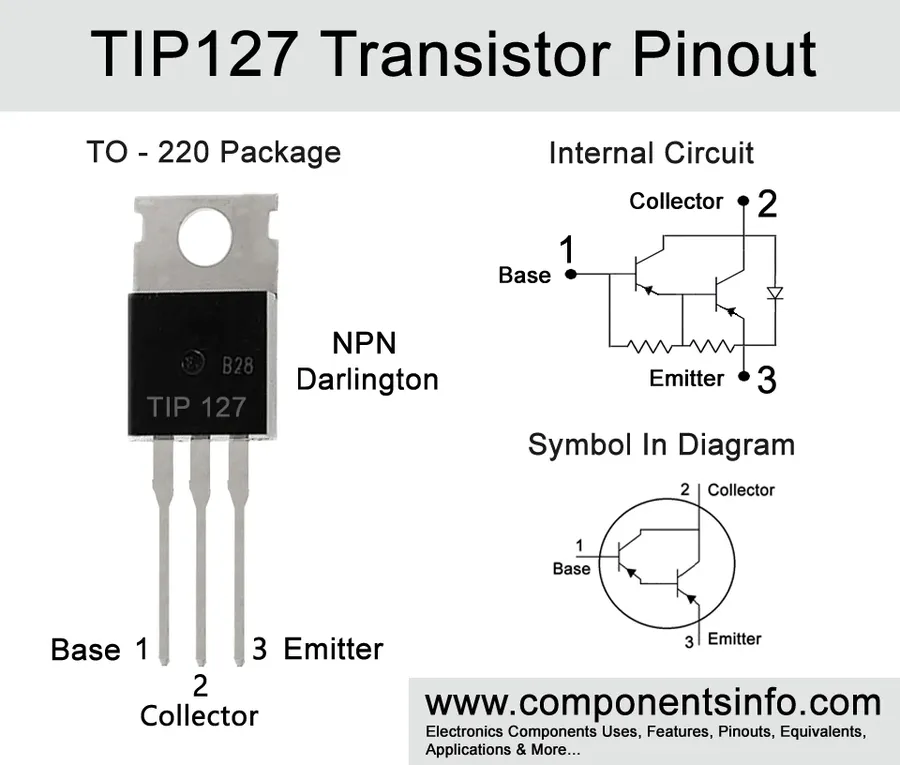
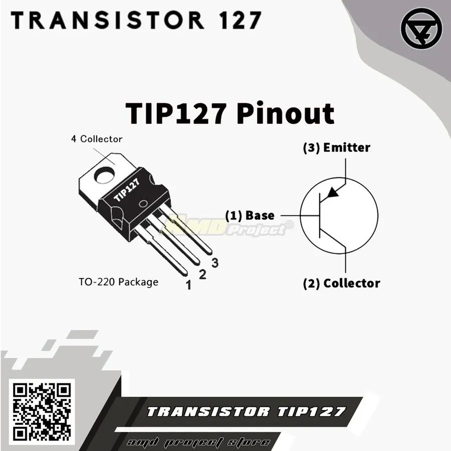
Pin Configuration: Identifying the Base, Collector, and Emitter
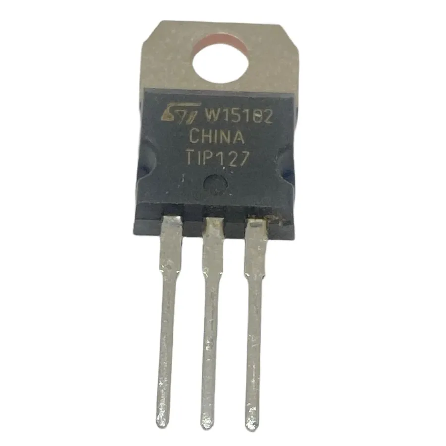
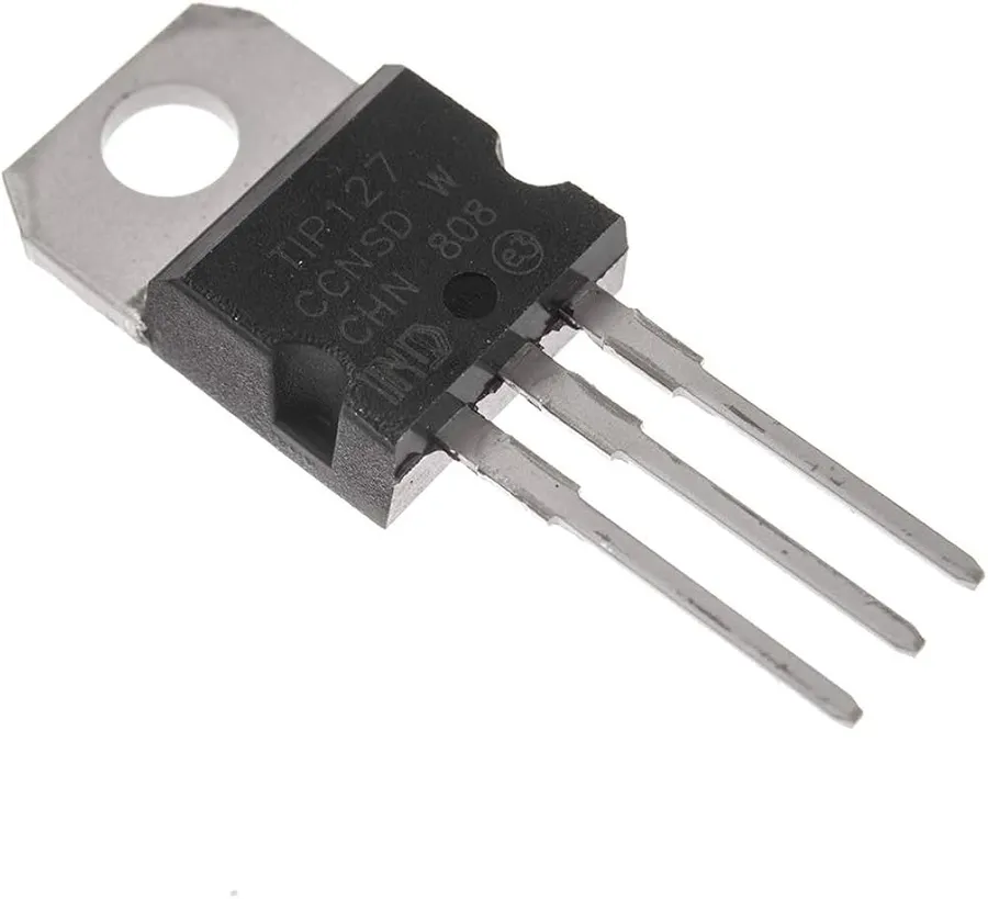
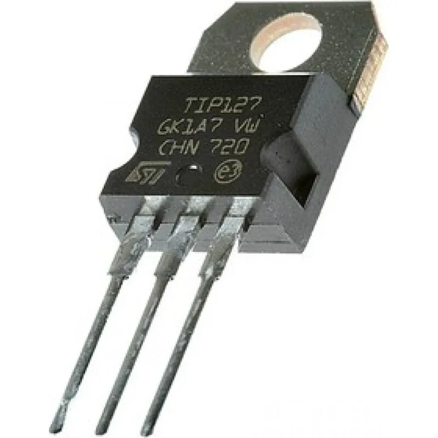
The TIP127 transistor, packaged in the common TO-220 format, has three pins: the base (B), collector (C), and emitter (E). Correctly identifying these pins is crucial for proper circuit integration. Incorrect connections can lead to component damage or circuit malfunction. This section provides a clear guide to pin identification, utilizing the TO-220 package diagram.
| Pin Number | Pin Name | Function |
|---|---|---|
| 1 | Base (B) | Controls the current flow between the collector and emitter. A small current at the base allows a larger current to flow from collector to emitter. |
| 2 | Collector (C) | The terminal where current flows into the transistor when it is in active mode. |
| 3 | Emitter (E) | The terminal where current flows out of the transistor. |
Looking at the TIP127 with the flat side of the TO-220 package facing you and pins pointing downwards, the leftmost pin is the Base, the middle pin is the Collector, and the rightmost pin is the Emitter. It's a consistent pattern across standard TO-220 packages and understanding this physical arrangement is key to its proper use.
Common Applications of the TIP127 Transistor
The TIP127 transistor, a versatile PNP Darlington transistor, finds its utility in a wide array of applications due to its ability to handle significant current loads. Its high current gain makes it suitable for tasks ranging from motor control to power switching, demonstrating its adaptability in various electronic circuits.
- Motor Control
The TIP127 can be used to drive DC motors, allowing precise speed and direction control by modulating the base current. Its Darlington configuration enables it to deliver the necessary current for many small to medium sized motors, making it suitable for robotics, automation and hobbyist projects. - Power Switching
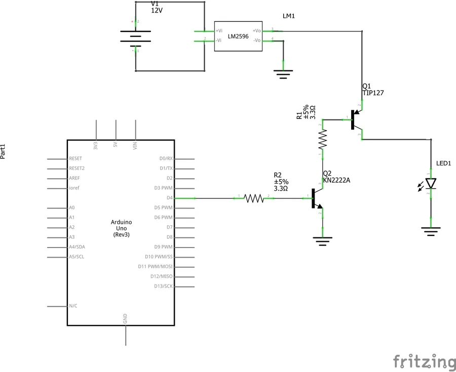
Acting as a switch, the TIP127 can control higher-power devices by switching them on or off using a small control signal applied to its base. This is useful in circuits where direct control of high currents or voltages is not feasible due to controller limitations. Example applications include turning on and off high-power LEDs and powering various system components. - Audio Amplification
While not a primary application, the TIP127 can be used in audio amplifier circuits, especially in the output stage of medium-power amplifiers, where its current handling capacity is beneficial. Its high current gain allows it to amplify weak signals to power speakers effectively. - General Purpose Switching Circuits
Beyond specific use-cases, the TIP127 serves as a general-purpose switching element in various other circuits, such as driving relays, solenoids, and other inductive loads due to its ability to handle high current. It is therefore used in diverse applications in electronic devices and systems. - Linear Regulator circuits
TIP127 can be employed in linear regulator circuits. It can efficiently regulate the output voltage, to ensure stable power supply for different electronic components. This application shows the versatility of TIP127 transistor in different circuits.
The TIP127 vs. Other Transistors: Comparisons and Selection
The TIP127 transistor, a PNP Darlington transistor, is frequently compared to other transistors, particularly the TIP122 (NPN Darlington) and the TIP102 (NPN Darlington), due to their similar use cases in power switching and amplification. Understanding their differences in specifications and characteristics is crucial for proper component selection in circuit design.
| Feature | TIP127 | TIP122 | TIP102 |
|---|---|---|---|
| Transistor Type | PNP Darlington | NPN Darlington | NPN Darlington |
| Polarity | PNP | NPN | NPN |
| Maximum Collector Current (Ic) | 5 A | 5 A | 8 A |
| Maximum Collector-Emitter Voltage (VCEO) | 100 V | 100 V | 80 V |
| Power Dissipation (Pd) | 65 W | 65 W | 80 W |
| Typical Application | High-side switching | Low-side switching | High current switching |
Key distinctions include the polarity (PNP for TIP127, NPN for TIP122 and TIP102), which dictates how they are used in circuits (high-side vs. low-side switching). While they share similar current and voltage ratings, the TIP102 offers a higher current capacity compared to the TIP127 and TIP122, making it suitable for higher power applications. The choice between these transistors depends on specific circuit needs, including current requirements, voltage levels, and desired switching configuration.
Testing the TIP127 Transistor: Ensuring Functionality
Properly testing a TIP127 transistor is essential to confirm its functionality before integrating it into a circuit and to troubleshoot issues effectively. Using a multimeter, we can assess key parameters and identify potential faults. This section provides a step-by-step guide on how to perform these tests to ensure the TIP127 operates as expected.
- Preparing for the test
Ensure that the TIP127 is disconnected from any circuit before testing to prevent damage and incorrect readings. Set your multimeter to the diode test mode (often indicated by a diode symbol) or resistance mode. Identify the base (B), collector (C), and emitter (E) pins of the TIP127, referring to the pinout diagram. - Testing the Base-Emitter Junction
Connect the multimeter's positive (red) lead to the base (B) and the negative (black) lead to the emitter (E). A healthy PNP transistor should show a voltage drop (approximately 0.7V for silicon transistors) in diode test mode. In resistance mode you should get a low resistance reading. - Testing the Base-Collector Junction
Move the negative (black) lead to the collector (C), keeping the positive (red) lead on the base (B). Again, a healthy junction should display a voltage drop of approximately 0.7V in diode test mode. A low resistance reading in resistance mode confirms connectivity - Testing the Collector-Emitter Junction
For a functional transistor, there should be no conduction in either direction when the multimeter leads are connected between collector and emitter pins. In diode mode, it should read OL (open loop). In resistance mode it should read very high resistance. If there is continuity, this suggests internal shorts and the transistor is faulty. - Interpreting the readings
If any of these tests shows significantly different values it suggests that the transistor is faulty. The most common failures are short circuits between pins, indicated by very low or zero resistance between pins, and open circuits, indicated by no voltage drop or very high resistance where a low reading is expected.
Finding TIP127 Equivalents: When Alternatives Are Needed
When the TIP127 transistor is unavailable or not the ideal choice for a specific application, suitable alternatives are crucial to maintain circuit functionality. Understanding the key specifications of the TIP127, such as its PNP polarity, Darlington configuration, and current and voltage ratings, is vital for selecting compatible replacements.
- Key Considerations for Equivalents
When selecting a TIP127 equivalent, the most important factors to consider include polarity (must be PNP for direct replacement), maximum collector current (Ic), collector-emitter voltage (Vceo), power dissipation (Pd), and the current gain (hFE), which must meet or exceed the TIP127's specifications. - Commonly Used TIP127 Equivalents
Some common alternatives include the TIP122 (though it is NPN, it requires a circuit modification) and other PNP Darlington transistors with similar voltage, current, and power ratings. The 2N6055 is also often suggested as a comparable alternative. Always refer to the datasheets of potential replacements to ensure compatibility. - Understanding Datasheets
Datasheets provide essential details about the characteristics of transistors. Pay close attention to the maximum ratings and operating conditions, which ensure that the substitute component will not fail under the same conditions where the TIP127 would operate safely.
While these alternatives offer similar performance in many applications, slight variations in specifications may require adjustments in circuit design or component selection to ensure optimal operation and prevent component damage. Always verify the pinout of the replacement transistor.
- FAQ: What are the critical parameters to consider when choosing a TIP127 equivalent?
The most critical parameters are polarity (PNP), collector-emitter voltage (VCEO), collector current (IC), power dissipation (PD), and current gain (hFE). Ensure these meet or exceed the TIP127's specifications. Also the package type (TO-220) and pinout. - FAQ: Can an NPN transistor be used as a direct replacement for a TIP127?
No, the TIP127 is a PNP transistor. An NPN transistor, such as the TIP122, cannot be a direct replacement without circuit modifications. The voltage polarity will need to be reversed to operate as an equivalent. - FAQ: What should I do if the datasheet of a potential equivalent does not list all parameters of TIP127?
If some parameters are missing, consult other resources, such as application notes or technical forums, to ensure the transistor is truly equivalent. Always verify the essential specifications against the TIP127 datasheet to ensure proper function. - FAQ: Where can I find reliable datasheets for transistors?
Reputable component manufacturers websites and reliable electronics distributors websites generally provide up-to-date and accurate datasheets for transistors. Websites like Mouser, Digikey, and manufacturer sites such as STMicroelectronics and ON Semiconductor provide reliable datasheets. - FAQ: Does the package of the replacement transistor matter?
Yes, the package type is vital for proper thermal management and physical fit. The TIP127 comes in a TO-220 package. The equivalent transistor should have a similar package type for easier integration and efficient heat dissipation, if you are substituting to a different package type then additional heatsinking may be necessary. - FAQ: Do I need to change my circuit biasing if using a different transistor?
Depending on the current gain (hFE) of the replacement transistor, you might need to adjust the biasing resistors. If the hFE is significantly different, the base current needed to drive the transistor may vary, potentially altering the circuit's performance. Using a potentiometer in the bias network is often a good idea for fine tuning.
Practical Considerations and Best Practices
Effective utilization of the TIP127 transistor necessitates attention to several practical aspects beyond basic circuit design. These considerations ensure optimal performance, prevent damage, and enhance the longevity of the transistor and associated circuitry. Proper heat management, correct wiring techniques, and appropriate biasing are crucial for reliable operation.
- Heat Sink Selection
Due to its role as a power transistor, the TIP127 generates heat during operation. The amount of heat increases with higher currents and voltages. Proper heat dissipation using an adequately sized heat sink is crucial. Consider thermal resistance calculations and the transistor's maximum junction temperature when choosing a heat sink. Ignoring this could lead to thermal runaway and premature failure. - Wiring Techniques
Employ correct wiring techniques to ensure reliable connections and avoid shorts or open circuits. Use appropriate gauge wires that can handle the expected current without excessive voltage drop or heat generation. Secure all connections to prevent accidental disconnections. Verify the pinout again before connecting to the circuit to avoid errors. - Biasing the TIP127
Appropriate biasing is essential for the TIP127 to operate within its specified limits and achieve the desired functionality. Incorrect biasing can lead to saturation or cut-off operation, affecting circuit performance. Carefully select resistor values to set the base current to achieve the required collector current and avoid exceeding the transistor's maximum ratings. The datasheet should be the main source for all the correct calculations. - Protection Circuits
Consider adding protection circuits to safeguard the TIP127 transistor. This includes surge protection and overcurrent protection to prevent damage from transient spikes or excessive current draw. Protective measures can increase the system’s reliability and lifespan. - Datasheet Adherence
Always consult the manufacturer's datasheet for the most accurate specifications and operating conditions. The datasheet contains vital information including maximum ratings, thermal characteristics, and suggested biasing configurations. Ignoring the datasheet can lead to unpredictable performance and device failure.
The TIP127 transistor's robust design and Darlington configuration make it an excellent choice for many power switching and amplification needs. Understanding its capabilities, limitations, and proper usage, ensures its effective application in various electronic projects. Just as a single component can define an entire structure, the TIP127 can be the cornerstone of your electronic circuit, driving efficiency and power.