Understanding the 100uF 25V Capacitor: Uses, Specs, and Replacement
In the realm of electronics, the seemingly small 100uF 25V capacitor plays a crucial role in countless circuits, acting as an energy buffer and smoothing voltage fluctuations. It's like the heart's ventricles, rhythmically managing the flow of electrical energy. This article will delve into the specifics of this component, exploring its types, applications and how a 100uf 25v capacitor can impact a wide range of electronics, from simple circuits to complex motherboards, guiding you through its significance with clarity and authority.
What is a 100uF 25V Capacitor?
A 100uF 25V capacitor is a fundamental passive electronic component designed to store electrical energy within an electric field. The designation '100uF' signifies its capacitance, which is 100 microfarads, indicating the amount of charge it can store at a given voltage. The '25V' denotes its maximum permissible operating voltage; exceeding this limit can lead to component failure. Typically, these capacitors are of the electrolytic type, characterized by higher capacitance values relative to other capacitor types.
Key Specifications and Types of 100uF 25V Capacitors
A 100uF 25V capacitor's performance and suitability for specific applications are largely determined by its key specifications and type. These parameters dictate how the capacitor behaves within a circuit, influencing its reliability and effectiveness.
| Specification | Description | Typical Values |
|---|---|---|
| Capacitance | The measure of a capacitor's ability to store charge. | 100 microfarads (uF) |
| Voltage Rating | The maximum DC voltage the capacitor can withstand without damage. | 25 Volts (V) |
| Tolerance | Permissible variation in the actual capacitance value. | +/- 20% (common) |
| Operating Temperature | The range of temperatures within which the capacitor can operate reliably. | -40°C to 105°C (typical range) |
| Equivalent Series Resistance (ESR) | Internal resistance within the capacitor that affects its efficiency. | Varies by type; lower is better for high frequency applications. |
| Leakage Current | Small current that flows through the capacitor even when not charging/discharging. | Varies by type; typically a few microamps. |
| Lifespan | Expected lifetime of the capacitor under normal operating conditions. | Typically several thousand hours at rated temperature and voltage. |
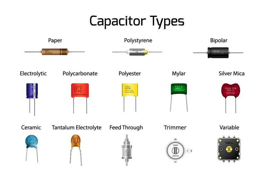
Understanding the different types of 100uF 25V capacitors is also essential. The most common types include:
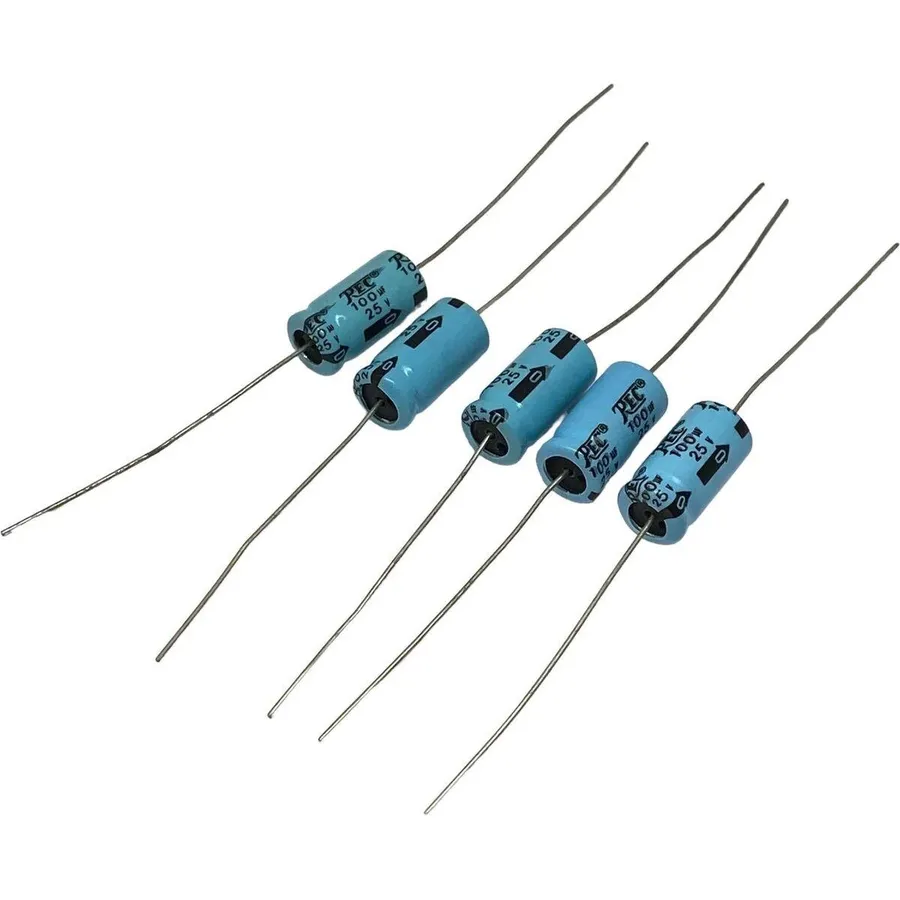
- Aluminum Electrolytic Capacitors
These are the most common type for 100uF 25V applications. They use an electrolyte to achieve high capacitance, but are polarized (require correct orientation in a circuit), have a shorter lifespan than some other types, and perform poorly at higher frequencies. - Solid Electrolytic Capacitors (e.g., Tantalum or Polymer)
These have a longer lifespan, better stability, and lower ESR compared to aluminum electrolytic types. However, they tend to be more expensive and may be sensitive to overvoltage. - Ceramic Capacitors
While less common at this specific capacitance and voltage rating due to physical size limitations, they offer superior performance at high frequencies. They are non-polarized.
Common Applications of the 100uF 25V Capacitor
The 100uF 25V capacitor is a workhorse in electronics, serving primarily as a filter and stabilizer within various power circuits. Its capacity to store and release electrical energy makes it invaluable for decoupling, smoothing, and timing applications. The core function is to ensure consistent and stable power delivery to sensitive electronic components, protecting them from voltage fluctuations and surges. Like small dams regulating water flow, these capacitors manage electrical current, preventing erratic operation in connected devices.
- Power Supply Decoupling
In power supplies, these capacitors are essential for decoupling noise from the DC power line. They act as a local energy reservoir, providing current when the load requires it and absorbing excess current when the load decreases, ensuring a stable voltage supply to integrated circuits and other components. This process reduces voltage ripple and transient spikes, leading to more reliable device operation. - Audio Amplifiers
Within audio amplifiers, 100uF 25V capacitors perform crucial functions such as filtering low-frequency noise and stabilizing bias voltages. They contribute to higher audio fidelity and reduce distortion by ensuring the amplifier receives a consistent and clean power supply. This results in clearer, more accurate audio reproduction and reduces unwanted hum or hiss. - Computer Motherboards
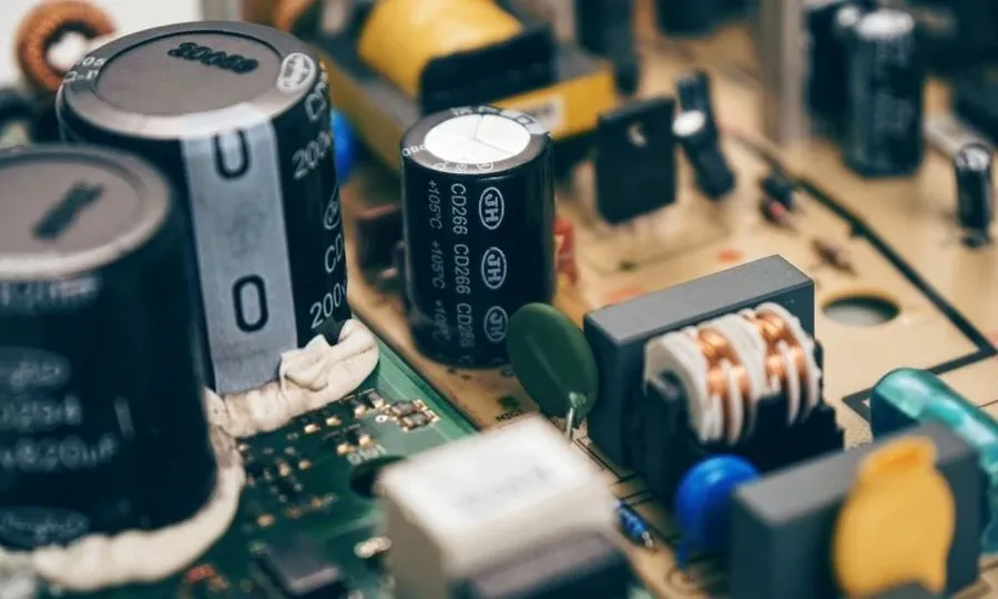
Motherboards use 100uF 25V capacitors extensively for decoupling and filtering power for various integrated circuits, especially near the CPU and RAM modules. These capacitors maintain the stability of the voltage supply, ensuring the sensitive microprocessors and memory modules operate correctly and reliably. Without these capacitors, motherboards could exhibit unstable performance and potential failures. - Timing Circuits
The capacitor, in combination with resistors, can be used to create timing circuits in many applications like timers, oscillators and signal generators. The charge and discharge of capacitor in RC circuits are the fundamental principle for many basic timing circuits. The specific capacitance values are determined by the specific timing requirements of the application. - General Electronics
Beyond specific applications, these capacitors are ubiquitous in general electronic devices, acting as filter components in a broad range of circuit designs. Their versatility and stability make them a preferred choice for tasks such as stabilizing power rails, buffering signal lines, and removing unwanted signal components. These help ensure the reliability and functionality of various electronic products.
Selecting the Right 100uF 25V Capacitor
Selecting the appropriate 100uF 25V capacitor is paramount for ensuring optimal circuit performance and longevity. This selection process requires a careful evaluation of several critical parameters beyond just the capacitance and voltage ratings. These considerations include the application's specific operational demands related to temperature, physical form factor, and electrical characteristics such as Equivalent Series Resistance (ESR), impedance, and expected lifespan. Neglecting these factors can lead to premature component failure or suboptimal performance.
To choose the right 100uF 25V capacitor, consider the following:
- Voltage Requirements
Ensure the capacitor's 25V rating meets or exceeds the maximum voltage expected in the circuit. Operating a capacitor beyond its rated voltage can lead to dielectric breakdown and failure. - Temperature Range
Match the capacitor's operating temperature range to the expected operating environment. For instance, high-temperature applications require capacitors rated for 105°C or higher, while standard applications may be satisfied with 85°C ratings. - Physical Form Factor
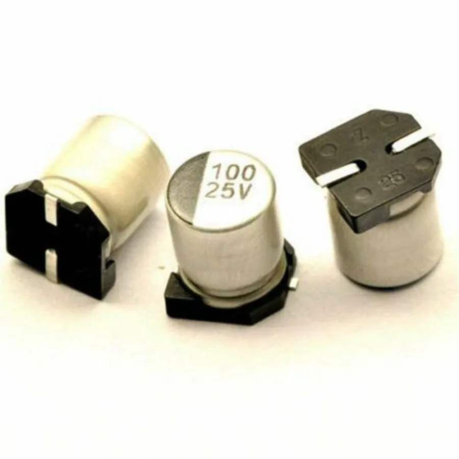
Select the appropriate mounting type (e.g., radial, surface mount (SMD), axial) based on your printed circuit board (PCB) layout and assembly process. Radial leads are through-hole components, SMD are for surface mounting, and axial leads go straight through the component body. - Equivalent Series Resistance (ESR)
For applications involving high-frequency switching, such as in power supplies, low ESR capacitors are preferred to minimize heat generation and improve efficiency. High ESR can lead to energy loss and overheating, impacting performance and longevity. The ESR value is usually stated in the datasheet. - Impedance
Impedance, which includes both the ESR and reactance, affects the capacitor's performance in AC circuits. Low impedance is desirable in circuits needing efficient energy transfer, such as decoupling and filtering. The impedance varies with frequency and is often detailed in the capacitor's datasheet, particularly for high frequency applications. - Lifespan
Consider the required operational lifespan. Electrolytic capacitors, for example, have a limited lifespan, which is influenced by temperature and ripple current. For demanding applications, capacitors with extended lifespans (often defined in hours at a specific temperature) are necessary. Choosing a capacitor with an expected lifespan that is similar or better than the device it is being used in is best. - Specialized Options
For demanding circuits, consider low-impedance capacitors, high temperature capacitors or capacitors with a longer lifespan if needed.
| Parameter | Importance | Considerations |
|---|---|---|
| Voltage Rating | Critical | Must meet or exceed application voltage |
| Temperature Range | Important | Match operating environment, especially for high temperature applications |
| Form Factor | Important | Select based on PCB design requirements |
| ESR | Critical for high-frequency applications | Low ESR preferred for efficient power conversion and low heat generation |
| Impedance | Important | Low impedance for efficient AC circuit operation |
| Lifespan | Important | Choose longer lifespans for critical and long operating devices. |
| Specialized options | Specific | Consider low impedance and high temperature for high-demand applications |
Understanding Capacitance and Voltage Rating
The core function of a capacitor, such as the 100uF 25V variant, lies in its capacity to store electrical charge. The '100uF' rating, specifically 100 microfarads, quantifies the amount of charge it can hold at a given voltage, while the '25V' represents the maximum voltage it can safely withstand before dielectric breakdown occurs. These ratings are fundamental in determining a capacitor's suitability for specific applications.
- Capacitance (100uF)
This is a measure of the capacitor's ability to store electrical charge. A higher capacitance value means the capacitor can store more charge at the same voltage. The unit 'uF' stands for microfarads (1uF = 1 x 10^-6 farads). - Voltage Rating (25V)
The voltage rating signifies the maximum DC voltage that can be safely applied across the capacitor terminals. Exceeding this voltage can lead to dielectric breakdown, resulting in capacitor failure and potential damage to the circuit.
| Parameter | Description | Effect of Higher Value | Effect of Lower Value |
|---|---|---|---|
| Capacitance (uF) | Measure of charge storage capacity | More charge can be stored | Less charge can be stored |
| Voltage Rating (V) | Maximum safe DC voltage | More robust under higher voltage conditions | Risk of failure at high voltage |
In practical terms, a 100uF capacitor at 25V can be used in a variety of applications where moderate capacitance and voltage requirements are needed, but care should be taken to not exceed its 25V rating or its operating parameters. Understanding these ratings is crucial for selecting the correct capacitor for your electronic design, as inappropriate values can lead to system malfunction or component failure.
How to Replace a 100uF 25V Capacitor
Replacing a 100uF 25V capacitor, while seemingly straightforward, requires careful attention to detail to avoid damaging the circuit or the new component. This process primarily involves desoldering the old capacitor and soldering in the new one, with particular emphasis on correct polarity.
- Preparation and Safety
Before beginning, ensure that the power is completely disconnected from the circuit to prevent electrical shock or damage. Gather necessary tools such as a soldering iron, desoldering pump or wick, solder, and the new 100uF 25V capacitor. Work in a well-ventilated area to avoid inhaling solder fumes. - Desoldering the Old Capacitor
Carefully heat the solder joints of the old capacitor's leads using the soldering iron. Once the solder is molten, use a desoldering pump or wick to remove the solder, freeing the leads. Avoid applying excessive force, which could damage the circuit board. Clean the solder pads thoroughly to ensure proper contact for the new capacitor. - Preparing the New Capacitor
Identify the polarity of the new capacitor. Typically, electrolytic capacitors have a longer lead indicating the positive terminal and a marking on the casing near the negative terminal. Confirm this using the product datasheet. - Installing the New Capacitor
Insert the new capacitor’s leads into the correct holes on the circuit board, ensuring the correct polarity is observed. Apply a small amount of solder to each lead, creating a strong and reliable connection. Avoid bridging solder between the leads or to other components. Ensure solder joints are smooth and not cold. - Post-Installation Check
After soldering, allow the capacitor and circuit board to cool down. Visually inspect the solder joints for proper connection and ensure no shorts have occurred. After inspection, reconnect power to the circuit for testing and proper operation, confirm the device works as intended.
Troubleshooting Common Issues with 100uF 25V Capacitors
Capacitors, while generally reliable, can experience failures. Identifying and addressing these issues promptly is crucial for the proper functioning of electronic devices. Common failure modes include physical damage, electrical degradation, and parameter shifts. This section details the common problems and how to use a multimeter to diagnose them.
- Bulging
A bulging capacitor is a clear sign of failure, often due to excessive internal pressure from electrolyte vaporization caused by overvoltage, reverse polarity or overheating. This usually requires replacement immediately, and the cause needs to be identified to prevent repeat failures. - Leakage
Electrolytic capacitors can leak their electrolyte over time, or due to physical damage. This leakage is corrosive and can damage the circuit board. A leaking capacitor should be replaced and the PCB should be cleaned. - Short Circuits
A shorted capacitor will show very low or zero resistance when measured by a multimeter. This condition is often the result of dielectric breakdown or physical damage, and the capacitor must be replaced. - Open Circuits
An open circuit will show infinite resistance on a multimeter. This can be caused by an internal break in the connections. Replacing the capacitor is necessary to restore the circuit operation. - Parameter Shifts
Capacitance and ESR (Equivalent Series Resistance) can shift over time or due to operating conditions. These shifts can cause erratic circuit behavior. Capacitance should be checked with a multimeter or dedicated meter.
When diagnosing a faulty capacitor, a multimeter is an indispensable tool. It can be used to check the resistance, and in some cases, the capacitance, providing clues about the condition of the capacitor.
Datasheet Analysis for 100uF 25V Capacitors
Datasheets for 100uF 25V capacitors are essential documents that provide detailed specifications about their electrical, physical, and performance characteristics. Analyzing these datasheets is crucial for selecting the correct capacitor for a given application and ensuring its reliable operation within a circuit.
- Key Parameters in a 100uF 25V Capacitor Datasheet
Datasheets commonly include parameters such as capacitance (100uF), rated voltage (25V), tolerance (e.g., ±20%), operating temperature range (e.g., -40°C to +105°C), Equivalent Series Resistance (ESR), leakage current, and physical dimensions. Understanding these parameters ensures that the capacitor meets the requirements of its intended application. - Capacitance and Tolerance
The datasheet specifies the nominal capacitance of the capacitor (100uF) and its tolerance. Tolerance indicates the acceptable variation in the actual capacitance value, typically expressed as a percentage (e.g., ±20%). This tolerance is important because real-world capacitor values may deviate from the nominal value, affecting circuit performance. - Rated Voltage
The rated voltage (25V) is the maximum DC voltage that the capacitor can safely withstand continuously. Operating the capacitor above this voltage can lead to dielectric breakdown, causing damage and potentially catastrophic failure. The datasheet will specify this maximum voltage under defined temperature conditions. - Temperature Characteristics
The operating temperature range defines the ambient temperatures in which the capacitor will function reliably. The datasheet will also show how capacitance, ESR, and lifespan may change over this temperature range. Exceeding this temperature range can result in accelerated degradation of the capacitor and lead to failure. - ESR (Equivalent Series Resistance)
ESR is a critical parameter, particularly in applications involving high frequencies and switching power supplies. A lower ESR is often preferred, as it reduces heat generation and improves efficiency. The datasheet may specify ESR values at different frequencies and temperatures. - Leakage Current
Leakage current is the small current that flows through the capacitor's dielectric even when it is not charging or discharging. This parameter becomes crucial in low-power circuits and long hold times. The datasheet will specify the maximum allowable leakage current, with temperature dependence. - Physical Dimensions and Packaging
The datasheet provides detailed information about the capacitor's physical dimensions and packaging type (e.g., radial, surface-mount). This is necessary for PCB design and proper component placement. Knowing the physical dimensions also allows assessment of its suitability in space-constrained applications. - Lifespan
The expected lifespan of a capacitor is often given in the datasheet. This is important for applications where long-term reliability is necessary. Capacitor lifespan is usually linked to operating temperature and voltage. This is especially relevant for aluminum electrolytic capacitors. - Frequency Response
Datasheets often include graphs and charts to show capacitance, ESR and impedance changes as frequency increases. This is a critical performance consideration, particularly in high-frequency applications.
By thoroughly analyzing the datasheet, engineers and technicians can confirm that a 100uF 25V capacitor is appropriate for their intended use, ensuring both performance and reliability.
Comparing 100uF 25V Capacitors to Similar Capacitors
Understanding the distinctions between a 100uF 25V capacitor and other common capacitor values is crucial for selecting the correct component for a given application. This section provides a comparative analysis with 1000uF 25V and 1uF capacitors, emphasizing their differences in application, size, and cost.
| Characteristic | 100uF 25V Capacitor | 1000uF 25V Capacitor | 1uF Capacitor |
|---|---|---|---|
| Capacitance | 100 microfarads (µF) | 1000 microfarads (µF) | 1 microfarad (µF) |
| Typical Application | Power supply decoupling, signal filtering, general purpose | Bulk energy storage, power supply smoothing | High-frequency signal filtering, coupling |
| Physical Size | Small to Medium (depending on type - radial, SMD, etc.) | Medium to Large (typically larger than 100uF) | Very Small (especially for ceramic or film types) |
| Cost | Moderate | Slightly higher than 100uF due to material | Lower than 100uF, often much cheaper in ceramic format |
| Voltage Rating | 25 Volts (V) | 25 Volts (V) | Varies, often higher (can be more than 25V) |
| ESR (Equivalent Series Resistance) | Varies but typically moderate, can be lower in solid type | Typically lower due to physical size, can be high depending on type | Often low, especially in ceramic type |
| Impedance | Moderate | Lower | Higher |
| Typical materials | Aluminum electrolytic, Tantalum, Solid Polymer | Aluminum electrolytic | Ceramic, Film, Tantalum |
Where to Buy 100uF 25V Capacitors
Sourcing authentic 100uF 25V capacitors from reputable distributors is crucial for reliable performance and safety in electronic applications. These components are readily available from a variety of suppliers, both online and in physical stores; however, vigilance is required to avoid counterfeit parts.
- Major Electronic Component Distributors
Leading distributors like Mouser Electronics, Digi-Key Electronics, and Arrow Electronics offer a wide selection of genuine 100uF 25V capacitors from various manufacturers. These distributors typically provide detailed datasheets and specifications. - Online Marketplaces
Platforms such as Amazon and eBay also list 100uF 25V capacitors. However, due to the potential presence of counterfeit products, it is imperative to verify the seller's reputation and the authenticity of the product before making a purchase. - Direct from Manufacturers
Purchasing directly from manufacturers such as Nichicon, Panasonic, or TDK offers a guarantee of authenticity. This option is often more suitable for bulk orders. - Smaller Online Retailers
Retailers such as Tayda Electronics often provide an affordable option for purchasing capacitors, but they need to be researched before purchase to avoid counterfeit parts. - Local Electronics Stores
Local electronic components stores are also an option to purchase capacitors, however the price is often higher than online retailers and the selection is usually limited.
It's critical to be aware of the risks associated with counterfeit components. Counterfeit capacitors can exhibit subpar performance, premature failure, and may pose safety hazards. To mitigate these risks, always source components from trusted and well-established suppliers. Verify the manufacturer's part number, review datasheets, and ensure the supplier has a reputation for providing authentic parts. Pay close attention to packaging and labeling; genuine components usually come in professional, high-quality packaging with proper identification marks. If prices seem unrealistically low, consider it a red flag and exercise caution. By adhering to these guidelines, you can confidently acquire the correct and reliable 100uF 25V capacitor for your specific application.
The 100uF 25V capacitor, while small, is a cornerstone of electronic circuits, enabling smooth operation and protecting components from voltage fluctuations. Whether for decoupling in power supplies or transient suppression, understanding its characteristics, correct usage and replacement is crucial. Knowledge and proper practices in selecting and using a 100uf 25v capacitor can ensure your electronic projects function flawlessly and reliably, underscoring the critical importance of this component in modern electronic systems.