Understanding the 4.7 uF Capacitor: Types, Uses, and Replacement Guide
In the realm of electronics, the 4.7 uF capacitor is a silent workhorse, often unseen but vital for circuit function. From smoothing voltage in power supplies to filtering signals in audio equipment, understanding its role is crucial. This article will delve into the 4.7 uF capacitor, exploring its various types, applications, and how to select the right one for your project, bridging the gap between scientific precision and everyday application.
What is a 4.7 uF Capacitor?
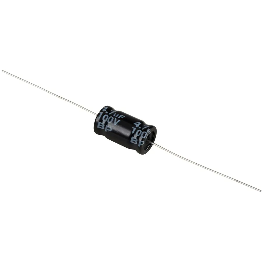
A 4.7 uF capacitor is a fundamental passive electronic component engineered to store electrical energy within an electric field, characterized by its capacitance of 4.7 microfarads (µF). This capacitance value dictates its ability to accumulate charge; the higher the capacitance, the more charge it can store at a given voltage. The unit 'uF' or 'µF' signifies microfarads, a millionth of a farad, the standard unit for capacitance.
- Key Characteristics:
Primarily, a capacitor's capacity to store electrical charge differentiates it. In the case of a 4.7µF capacitor, this value indicates the extent of charge storage. The structure of this capacitor typically comprises two conductive plates, often metallic, separated by an insulator referred to as a dielectric. Capacitors are indispensable within electronic circuits for a variety of functions, including filtering, energy storage, and signal coupling. Their design and properties must correspond precisely with the specific demands of the application.
Types of 4.7 uF Capacitors
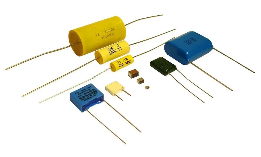
4.7 uF capacitors are essential components in electronic circuits, with their diverse types catering to specific application needs. Understanding the characteristics of each type is crucial for selecting the right capacitor for a given application. The primary types include Aluminum Electrolytic, Metallized Polyester Film, and Ceramic capacitors, each distinguished by their construction, polarization, and performance.
| Capacitor Type | Polarization | Pros | Cons | Typical Applications |
|---|---|---|---|---|
| Aluminum Electrolytic | Polarized | High capacitance per volume, relatively low cost | Limited lifespan, higher ESR (Equivalent Series Resistance), sensitive to temperature and polarity. | Power supply filtering, decoupling |
| Metallized Polyester Film | Non-Polarized | Good stability, low ESR, durable | Larger size compared to other types, higher cost | Audio signal coupling, timing circuits |
| Ceramic | Non-Polarized | Small size, low cost, good high-frequency performance | Capacitance changes with voltage and temperature, limited capacitance values | High-frequency filtering, decoupling in digital circuits |
- Aluminum Electrolytic Capacitors:
These are polarized capacitors, meaning they must be installed with the correct polarity. They are characterized by their high capacitance per unit volume, making them suitable for applications requiring significant energy storage. However, they tend to have higher ESR and limited lifespan compared to other types. - Metallized Polyester Film Capacitors:
These are non-polarized capacitors known for their good stability, low ESR, and durability. They are often used in applications that require precise performance and are more tolerant of environmental changes. However, they are typically larger in size compared to ceramic capacitors. - Ceramic Capacitors:
Ceramic capacitors are non-polarized and are valued for their small size, low cost, and good high-frequency performance. They are widely used in digital and high-frequency circuits. However, their capacitance can vary with voltage and temperature changes and they typically have lower capacitance values compared to aluminum electrolytic capacitors.
Common Applications of 4.7 uF Capacitors
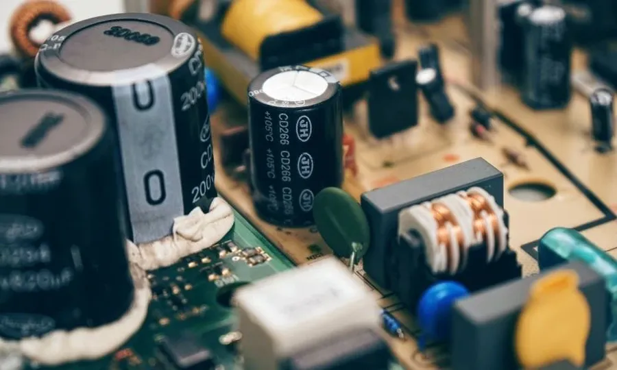
The 4.7 uF capacitor is a versatile component, essential in numerous electronic circuits due to its ability to store and release electrical energy. Its applications span from basic power supply stabilization to critical audio signal processing.
- Power Supply Smoothing
In power supply circuits, a 4.7 uF capacitor acts as a filter, smoothing out voltage ripples and fluctuations to ensure a stable and consistent power source for sensitive electronic components. This is critical for the proper operation of integrated circuits and microcontrollers. - Audio Signal Filtering
4.7 uF capacitors are employed as filters in audio circuits. They can block DC components while allowing AC audio signals to pass through, leading to clearer and cleaner sound output. The use of this capacitor can also remove unwanted low-frequency noise. - Bass Blocking in Audio Systems
In audio systems, particularly those using tweeters, a 4.7 uF capacitor functions as a high-pass filter, blocking low-frequency signals. This protects the tweeter from being damaged by strong low-frequency signals, while also sending higher frequencies, which are needed for clear audio reproduction. - Timing Circuits
4.7 uF capacitors are used in timing circuits. When paired with resistors, they create a time constant that affects the charging and discharging times and sets the timing for different operations within a system. These circuits are found in applications such as oscillators and pulse generators. - Signal Coupling
In multi-stage amplifiers or other analog circuits, 4.7 uF capacitors are used for signal coupling. These capacitors pass AC signals from one stage to another while blocking DC voltage. This is critical for preventing DC offset and allowing each stage to operate at its designed bias point. The proper selection of this capacitor also prevents loading effects in circuits.
4.7 uF Capacitor Voltage Ratings Explained
The voltage rating of a 4.7 uF capacitor is a critical parameter that indicates the maximum voltage the capacitor can safely withstand without risk of failure or damage. Understanding this rating is essential for selecting the appropriate capacitor for a given application. Operating a capacitor above its rated voltage can lead to dielectric breakdown, causing permanent damage and potentially compromising the entire circuit.
- Importance of Voltage Rating
The voltage rating is not the operating voltage but rather the maximum voltage the capacitor can handle. It is imperative to use capacitors with voltage ratings that meet or exceed the expected maximum voltage in a circuit to ensure reliable operation and safety. - Common Voltage Ratings
4.7 uF capacitors are available in various voltage ratings, including 50V, 100V, 250V, and higher. The selection should be based on the application's voltage requirements. Common low-voltage applications usually require at least 16V, while high-voltage applications can demand hundreds of volts. - Safety Margin
It is generally recommended to use a capacitor with a voltage rating that provides a safety margin above the expected maximum voltage in a circuit. For example, if a circuit operates at 24V, using a 50V capacitor is advisable. This safety margin provides a buffer for voltage fluctuations and transients. - Polarized vs Non-Polarized Capacitors
Electrolytic capacitors, a common type in 4.7uf, are polarized and they can only operate correctly if the voltage polarity applied to them is the same polarity indicated on the capacitor, otherwise they will fail and leak or even explode. Non-polarized capacitors, such as ceramic and film capacitors, on the other hand, can withstand voltage of both polarities.
| Voltage Rating | Typical Applications | Considerations |
|---|---|---|
| 16V - 50V | Low-voltage DC circuits, general electronic applications | Commonly found in power supplies, signal coupling and filtering |
| 100V | Medium-voltage power circuits, automotive electronics | Suitable for moderately demanding environments |
| 250V - 630V | High-voltage applications, power electronics, and industrial equipment | Must be used in environments with high electrical stress |
Decoding 4.7 uF Capacitor Codes
Capacitor markings, often appearing as seemingly cryptic codes, are essential for identifying the component's characteristics. These codes provide information beyond the nominal capacitance (4.7 uF), such as voltage rating, tolerance, temperature coefficient, and even the manufacturing date. Understanding these markings is crucial for proper component selection and replacement, ensuring circuit integrity and performance.
- Capacitance Code
The primary value, 4.7 uF, is often explicitly stated, but may also be represented through a numerical or alphanumeric code. For instance, a three-digit code might use the first two digits for the value and the third for the multiplier. A code like '475' might mean 47 x 10^5 pF = 4.7 uF. - Voltage Rating Code
The maximum voltage the capacitor can withstand is critical. It may be directly indicated (e.g., '100V'), or encoded (e.g., a letter code). For example, a code might indicate 100 volts or 250 volts. Refer to manufacturer's datasheets to decode these codes. - Tolerance Code
Capacitance values have tolerances specified. Codes, often letters, indicate the permissible deviation from the nominal value (e.g., 'K' might represent a ±10% tolerance). A tighter tolerance is critical for applications needing high accuracy. - Temperature Coefficient
Some capacitors display a code indicating how the capacitance changes with temperature. This is essential for applications where temperature stability is critical, such as precision timing circuits. - Manufacturer Codes
Some markings identify the manufacturer, allowing for traceability or specific component identification for replacement. - Date Code
Date codes indicate the production time, which is useful for identifying potential end-of-life issues in older capacitors.
It's important to note that capacitor coding can vary across manufacturers and component types (ceramic, electrolytic, film, etc.). Always refer to the manufacturer's datasheet for the specific capacitor to accurately decipher the codes.
Replacing a 4.7 uF Capacitor: A Practical Guide
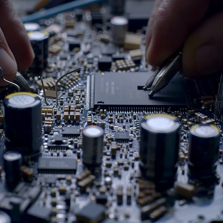
Replacing a 4.7 uF capacitor requires a systematic approach to ensure proper functionality and safety of the electronic device. This section details the essential steps and considerations for a successful capacitor replacement.
- Safety First
Always discharge the circuit completely before handling any components. This prevents electric shock and damage to the components. Use appropriate tools, such as an insulated screwdriver, and a multimeter to verify the absence of voltage. - Identify the Correct Replacement
Carefully check the existing capacitor for its capacitance (4.7 uF), voltage rating, tolerance, and size/lead type. The replacement must match the voltage rating or have a higher one, and must have the same capacitance. A higher voltage rating is acceptable but not lower, while minor variations in capacitance *may* be acceptable *in some cases*, but it's strongly recommended to stick to the original 4.7uF. - Desoldering the Old Capacitor
Use a soldering iron to carefully melt the solder joints on the old capacitor's leads. Employ a desoldering tool or solder wick to remove the solder completely from the connection points. Take care not to damage the circuit board traces or pads. It's good practice to document the polarity of polarized capacitors like electrolytic ones before removing them. - Preparing the New Capacitor
If the new capacitor has leads that are too long or too short, trim them to the appropriate length. If the lead style is different, you may need to adapt them for proper insertion. Be mindful of polarity in electrolytic and tantalum capacitors. Some may also be surface-mount and need other considerations for the soldering. - Soldering the New Capacitor
Position the new capacitor correctly and solder its leads to the circuit board. Apply sufficient solder to create a solid electrical and mechanical connection. Avoid overheating the capacitor or the board which can cause damage. For SMD components, hot-air or reflow soldering may be required. - Post-Replacement Checks
After soldering, visually inspect the joints for a clean, secure connection. Once the board has cooled down, test the circuit using a multimeter to check for shorts or open circuits and correct voltage and current behavior. It's always recommended to test the device after the replacement before finally closing the enclosure.
Can I Use a Different Value Capacitor Instead of 4.7 uF?
The selection of a capacitor with an appropriate capacitance is crucial for optimal circuit operation. While minor deviations from the specified 4.7 uF value might be acceptable in some situations, significant differences can lead to performance degradation or malfunction of the electronic device. The impact of using a different value primarily revolves around the change in capacitance, which directly affects the circuit's behavior.
- Impact of Higher Capacitance Values
Substituting a 4.7 uF capacitor with one of slightly higher capacitance may be tolerable in some applications. However, this approach can result in altered circuit time constants, which may affect timing, filter characteristics, and power supply smoothing. While a small increase may be acceptable, large increases in capacitance are strongly discouraged, as they can cause instability or even damage to other components. - Impact of Lower Capacitance Values
A lower capacitance value than 4.7 uF significantly reduces the available charge storage capacity of the component. This decrease will negatively affect the functionality of circuits dependent on specific capacitance values, particularly those in timing, filtering, or coupling applications. For instance, in an audio circuit, using a lower value than 4.7uF will cause more of the bass frequencies to go to the tweeter which can damage the tweeter or reduce the sound quality. Using a capacitor with lower capacitance than the original is highly discouraged and can lead to improper functionality. - Importance of Original Value
To maintain the intended circuit performance, using a capacitor that matches the original 4.7 uF value is generally recommended, unless a different value is explicitly specified in the manufacturer's specifications. This ensures all components operate as designed, maintaining performance, stability, and functionality. If you are unsure about the impact of using a different capacitor value, consult a professional or an authorized service center for expert recommendations.
In summary, while slight variations may seem insignificant, they can cause a significant alteration of the performance of the circuit. It is always best to use the specified 4.7 uF component unless there is clear documentation that a different value will work as a replacement. Always consider the consequences before introducing changes to the circuit, especially with critical components like capacitors.
4.7 uF Capacitor in Audio Systems
In audio systems, the 4.7 uF capacitor serves crucial roles, primarily as a coupling capacitor and a bass blocker, effectively acting as a high-pass filter. This capacitor is strategically placed to selectively allow higher frequencies to pass through while attenuating lower frequencies. This is particularly useful in directing audio signals to tweeters or amplifiers, ensuring that only the necessary frequency components reach the specific components and contribute to the overall sound quality.
- Coupling Capacitor Function
As a coupling capacitor, the 4.7 uF component prevents DC signals from passing between different stages of an audio circuit. This is essential to avoid unwanted DC offsets that can negatively impact sound reproduction. - Bass Blocking and High-Pass Filtering
In its capacity as a bass blocker, the capacitor filters out low frequencies which is essential when driving tweeters, as they are not designed to reproduce low frequency signals. This prevents damage to the tweeter and ensures clear and distinct high-frequency output. - Impact of Capacitor Type on Sound Quality
The type of 4.7 uF capacitor used can have a significant influence on the sound quality. Film capacitors such as metallized polyester film are often preferred for their low distortion and stability, while electrolytic capacitors may introduce more distortion but are suitable in less critical applications where cost and size are primary concerns. - Typical Placement in Audio Circuits
You will usually find 4.7uF capacitors between stages of an audio amplifier, between the amplifier output and a tweeter, or within active or passive filters to shape the frequency content of the signal.
| Capacitor Type | Advantages | Disadvantages | Typical Applications in Audio |
|---|---|---|---|
| Metallized Polyester Film | Low distortion, Stable with temperature, Non-polarized | Larger size than ceramic, May be more expensive | High-fidelity audio coupling, Filter networks |
| Ceramic | Small size, Low cost, Non-Polarized | Can be sensitive to voltage and temperature, May exhibit microphonics | General purpose signal filtering, Coupling in less critical areas |
| Aluminum Electrolytic | High capacitance, Low cost | Polarized, higher distortion, higher tolerances, Shorter lifespan than film capacitors | Power supply filtering in audio, Output coupling where polarity is not a factor |
Troubleshooting Issues with 4.7 uF Capacitors
Effective troubleshooting of 4.7 uF capacitors involves identifying common failure modes such as physical damage, electrical parameter shifts, or complete circuit failure. Early detection and proper testing are crucial for maintaining the performance and reliability of electronic devices. This section will guide you through the methods of identifying these issues and how to use tools like a multimeter to assess the capacitor's condition, emphasizing the significance of verifying specifications before any replacement.
- Physical Inspection
Visually examine the capacitor for signs of physical damage, such as bulging, cracking, or leaking electrolyte. Bulging, in particular, indicates overpressure due to heat or overvoltage, which is a critical failure sign. - Capacitance Testing
Use a multimeter with a capacitance measurement function to test the capacitor's capacitance. A reading that deviates significantly from the 4.7 uF value, especially a much lower value or zero, indicates a problem. This test confirms that the capacitor is holding the charge as it should. - ESR Testing
Equivalent Series Resistance (ESR) can also be an important indicator of a capacitor’s health. A significant increase in ESR can indicate degradation or aging of the capacitor even if its capacitance is still within tolerance. - Continuity Testing
When a capacitor presents as an open circuit, then there will be no continuity between the two leads. A short circuit can also be detected if very low resistance between the leads is detected, which also means the capacitor has failed. - Voltage Rating
Ensure that any replacement capacitors have the same or higher voltage rating than the original. Exceeding the voltage rating can lead to failure, which may be catastrophic and potentially dangerous. - Polarity
When replacing polarized capacitors, such as electrolytic types, be sure to maintain correct polarity. Incorrect polarity can cause damage and result in incorrect device behavior. Some capacitors such as ceramic capacitors are not polarized so they can be inserted in any orientation. - Specification Verification
Before replacing, always verify the original capacitor’s specifications (capacitance, voltage rating, temperature range, size, type) against the datasheet to ensure the replacement is suitable.
The 4.7 uF capacitor, seemingly small and simple, plays a crucial role in a vast array of electronic circuits. From smoothing power supplies to fine-tuning audio signals, its impact is undeniable. A solid understanding of its types, applications, and replacement guidelines not only empowers electronics enthusiasts but also highlights the intricate relationship between fundamental components and the technology that surrounds us. The 4.7 uf capacitor, a seemingly small component, powers a wide array of electronic devices. By mastering the concepts we discussed today, we equip ourselves with the technical expertise to build, repair, and innovate better electronics.