BC557 Transistor: Pinout, Datasheet, Equivalents & Applications
In the ever-evolving world of electronics, the BC557 transistor stands as a fundamental component, much like the foundation of a skyscraper. This PNP bipolar junction transistor, commonly found in various electronic circuits, plays a critical role in amplification and switching, akin to how a simple switch controls a room's light. Whether you're a seasoned engineer or a curious hobbyist, understanding the BC557 opens doors to innovative circuit designs and deeper insights into the fascinating world of electronics.
Understanding the BC557 Transistor
The BC557 is a widely utilized PNP bipolar junction transistor (BJT), characterized by its ability to amplify or switch electronic signals. It's fundamental to many circuit designs, acting as a current-controlled device, where a small current at the base controls a larger current between the collector and emitter.
BC557 Pin Configuration and Functionality
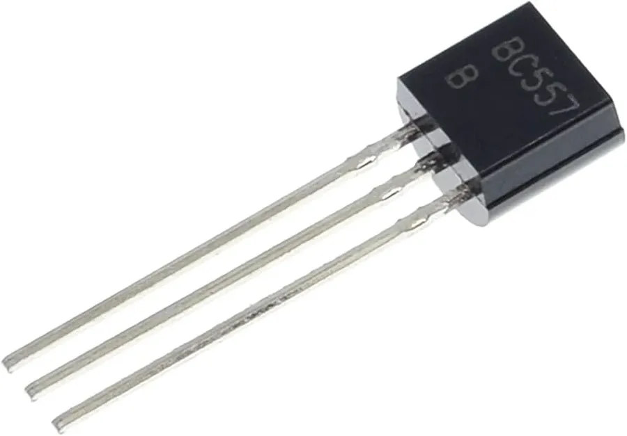
The BC557 is a PNP bipolar junction transistor characterized by three terminals: the emitter, the base, and the collector. Each of these pins plays a unique role in the transistor's operation and interaction within a circuit. Understanding these roles is crucial for effective circuit design using the BC557.
| Pin | Description | Functionality |
|---|---|---|
| Emitter (E) | The terminal that emits or injects charge carriers (holes in the case of a PNP transistor). | Typically connected to the power supply (positive terminal in most applications with PNP transistors) or output depending on the circuit configuration. It serves as the source of current flow within the device. |
| Base (B) | The control terminal that regulates the flow of current between the emitter and the collector. | A small current applied to the base controls the larger current flow between the collector and emitter. For the BC557, current flows *out* of the base to turn on the transistor. |
| Collector (C) | The terminal that collects charge carriers (holes) emitted by the emitter. | Usually connected to the load or another component in the circuit. The collector current is controlled by the base current, with the transistor amplifying the effect. |
Key Specifications from the BC557 Datasheet
Understanding the key specifications outlined in the BC557 datasheet is paramount for effective circuit design and application. These parameters dictate the transistor's behavior and limitations, ensuring optimal performance and preventing potential damage. The following details the critical specifications to consider.
| Parameter | Symbol | Typical Value | Unit | Importance for Circuit Design |
|---|---|---|---|---|
| Collector-Emitter Voltage | VCEO | -45 | V | Maximum voltage the transistor can withstand between collector and emitter. Exceeding this limit can lead to breakdown. |
| Collector Current | IC | -100 | mA | Maximum current allowed to flow through the collector. This is critical for determining the load the transistor can handle. |
| Collector Power Dissipation | PC | 625 | mW | Maximum power the transistor can dissipate without overheating. Important for thermal management in the design. |
| Current Gain (hFE) | hFE | 110-800 | - | The ratio of collector current to base current, influencing the transistor's amplification capabilities. hFE varies between individual transistors, and is therefore a critical range to consider. |
| Transition Frequency | fT | 100 | MHz | The frequency at which the current gain of the transistor drops to unity. Important in high-frequency applications. |
The stated values are typically specified at 25 degrees Celsius and can vary based on operating conditions. Always consult the specific datasheet provided by the manufacturer for accurate and up-to-date information. Temperature fluctuations can significantly impact parameters like current gain, and this is a factor in real-world circuit performance
BC557 as an Amplifier

The BC557, a PNP bipolar junction transistor, is frequently utilized in small-signal amplification circuits due to its inherent characteristics. Its ability to amplify current makes it a valuable component in a variety of electronic applications, particularly where a negative-voltage driven amplification is required. This section explores common amplifier configurations, essential biasing techniques, and the inherent advantages of using a PNP transistor like the BC557 for signal amplification.
When designing an amplifier using the BC557, several configurations are commonly employed. The most basic configurations include Common Emitter, Common Collector, and Common Base. Each offers a different set of characteristics and tradeoffs such as input/output impedance, gain, and phase. The selection of the configuration depends on specific design requirements.
- Common Emitter Configuration
The common emitter configuration provides high voltage and current gain, with the output signal 180 degrees out of phase with the input. It is the most common configuration and is used in a wide variety of amplification stages. - Common Collector Configuration
Also known as an emitter follower, this configuration provides high input impedance and low output impedance, making it suitable for impedance matching applications. It has a voltage gain of approximately 1, and output signal is in phase with the input. - Common Base Configuration
The common base configuration is used for high-frequency applications due to its low input impedance and high output impedance. It offers a voltage gain but no current gain and output signal is in phase with the input.
Biasing is an essential aspect of designing an amplifier using the BC557. The primary goal of biasing is to set up the transistor's operating point (Q-point) such that the output signal does not saturate or cutoff the transistor. An incorrectly biased transistor can lead to distortion and low signal fidelity. Proper biasing ensures the amplifier operates in its linear region, allowing it to faithfully amplify the input signal. Typical biasing methods include: Fixed Bias, Collector Feedback Bias and Voltage Divider Bias, each offering different stability characteristics with variation in temperature and transistor characteristics. For better stability and temperature independency, voltage divider biasing is usually preferred.
The use of a PNP transistor like the BC557 offers distinct advantages in certain amplifier applications. PNP transistors are particularly useful when an amplification stage requires an inverted output in response to a change in the input signal (in reference to a positive supply). This can simplify circuit design in scenarios where logic signals are active-low or when a negative supply voltage is available in the circuit.
| Feature | NPN Transistor | PNP Transistor (BC557) |
|---|---|---|
| Bias Current Direction | Current flows into the collector | Current flows out of the collector |
| Active Region Input | Positive voltage at the base relative to the emitter | Negative voltage at the base relative to the emitter |
| Application | Common for low-side switching | Often used for high-side switching and inverting amplifier stages |
BC557 as a Switch
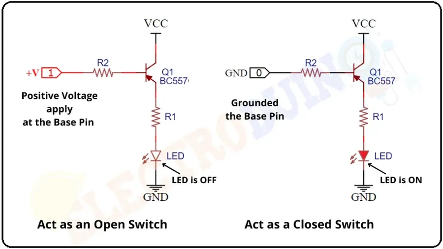
The BC557 transistor, when configured appropriately, can act as an efficient electronic switch. In this mode, the transistor either allows current to flow freely (ON state) or blocks current flow (OFF state). This functionality is crucial in various digital and analog circuits, where the control of current flow is essential.
The BC557, being a PNP transistor, requires a low or zero voltage on its base to activate the switch. Conversely, a higher voltage on the base will cut off current through the collector-emitter path, effectively stopping the flow. This behavior makes the BC557 ideal for applications where a negative going control signal is required to switch on a load.
The effectiveness of the BC557 as a switch is characterized by two key parameters: switching speed and saturation characteristics. Switching speed refers to how quickly the transistor can transition between the ON and OFF states. The saturation region refers to the state where the transistor is fully ON, with minimal voltage drop across the collector-emitter terminals, enabling it to act like a closed switch.
| Parameter | Description | Relevance to Switching |
|---|---|---|
| Switching Speed | Time taken to transition between ON and OFF states | Determines maximum switching frequency |
| Saturation Voltage (VCE(sat)) | Collector-emitter voltage when fully on | Indicates power loss and performance |
| Base Current (IB) | Current required at base to achieve saturation | Affects switching and current control |
BC557 Equivalent Transistors
The BC557, a widely used PNP bipolar junction transistor, can often be substituted with other transistors when specific circuit requirements or component availability necessitates a change. Understanding the characteristics and limitations of these equivalent transistors is critical for reliable circuit design and troubleshooting. This section details common alternatives and their suitability as replacements for the BC557.
| Parameter | BC557 | BC556 | BC558 | 2N3906 |
|---|---|---|---|---|
| Polarity | PNP | PNP | PNP | PNP |
| Collector-Emitter Voltage (VCEO) | -45V | -45V | -30V | -40V |
| Collector Current (IC) | -100mA | -100mA | -100mA | -200mA |
| Power Dissipation (Pd) | 500mW | 500mW | 500mW | 350mW |
| Transition Frequency (fT) | 100MHz | 100MHz | 100MHz | 250MHz |
| Current Gain (hFE) | 110-800 | 110-800 | 120-800 | 100-300 |
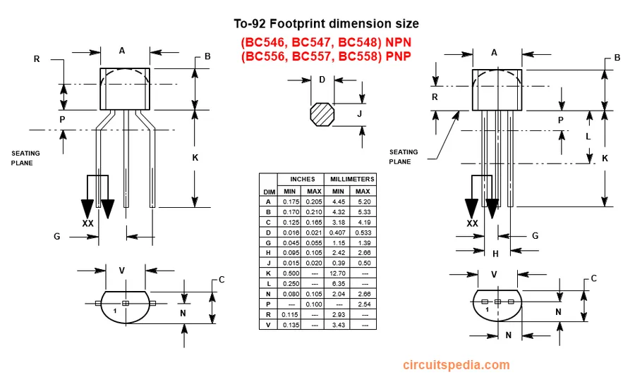
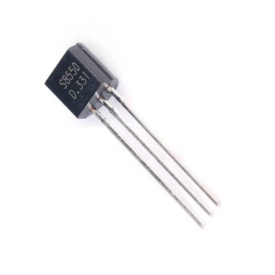
| Package | TO-92 | TO-92 | TO-92 | TO-92 |
While the BC556 and BC558 are often directly substitutable in many applications given similar key characteristics, it is imperative to verify parameter compatibility such as VCEO, IC, and hFE. The 2N3906 is a viable alternative for the BC557 with slight variations in specifications. The slightly lower power dissipation requires careful consideration in power-sensitive circuits, while the higher transition frequency of 2N3906 may be advantageous in high-frequency applications.
When selecting an equivalent, engineers must review the datasheet of the selected equivalent to ensure it will meet the application-specific requirements, such as voltage, current, gain, and frequency response. Additionally, temperature dependency should be taken into account where appropriate to ensure the circuit reliability under various operating conditions.
Frequently Asked Questions About the BC557 Transistor
This section addresses common inquiries regarding the BC557 transistor, clarifying its characteristics, applications, and distinctions from similar components. We aim to provide clear, concise answers to help you understand and effectively use the BC557 in your electronic projects.
- What is the primary function of a BC557 transistor?
The BC557 is primarily used as a PNP bipolar junction transistor. It functions as an electronic switch or amplifier by controlling current flow between the collector and emitter based on the current applied to the base. Its PNP nature means it conducts when the base is pulled low relative to the emitter. - How does the BC557 differ from the BC547?
The BC557 and BC547 are complementary transistors. The BC557 is a PNP transistor, meaning it is activated by a low voltage at the base, while the BC547 is an NPN transistor, activated by a high voltage at the base. This difference dictates how they are used in circuits and their polarity requirements. They can be used together in push-pull configurations or as complementary parts of a circuit. - What does 'PNP' mean in the context of the BC557 transistor?
'PNP' refers to the internal structure of the transistor, consisting of a layer of N-type semiconductor material sandwiched between two layers of P-type material. This structure means that the BC557 conducts when the base is pulled to a lower voltage than the emitter, using a negative base-emitter voltage to turn the transistor on. - Is the BC556 a PNP or NPN transistor?
The BC556 is a PNP transistor, similar to the BC557. It shares the same operating principle, structure, and activation requirements. The primary difference lies in their specific electrical parameters like voltage and current ratings, but fundamentally both are PNP devices. - In what types of circuits is the BC557 commonly used?
The BC557 is often used in small-signal amplification, switching applications, and as a driver for other transistors. Its application areas span from audio amplifiers to simple electronic switches in low to medium power devices. Its role in a circuit is defined by its ability to amplify current and switch based on the input signal at its base. - Can the BC557 be used as a switch?
Yes, the BC557 can be used as an electronic switch. When the base is pulled to a lower voltage compared to the emitter, it allows current to flow from the emitter to the collector. This on/off functionality makes it suitable for switching circuits, especially where low current or voltage levels are involved. - What are some key parameters to consider when selecting a BC557 transistor for a project?
Key parameters include current gain (hFE), collector-emitter voltage, collector current, and power dissipation. Understanding these parameters will ensure the BC557 operates within its safe limits and performs as expected in the specific application and circuit requirements.
Practical Applications and Circuit Examples
The BC557 PNP transistor's versatility allows it to be used in a wide range of applications, from basic switching to more complex amplification circuits. Its ability to control current flow makes it a valuable component in many electronic designs. Below, we explore some common uses with example circuits.
Audio Amplifier Circuit: In audio applications, the BC557 can be configured as a preamplifier to amplify weak audio signals. A common emitter configuration is often used, where the input signal is applied to the base, and the amplified output is taken from the collector. This configuration provides a high voltage gain. The proper biasing is important to set the operation point in the linear region.
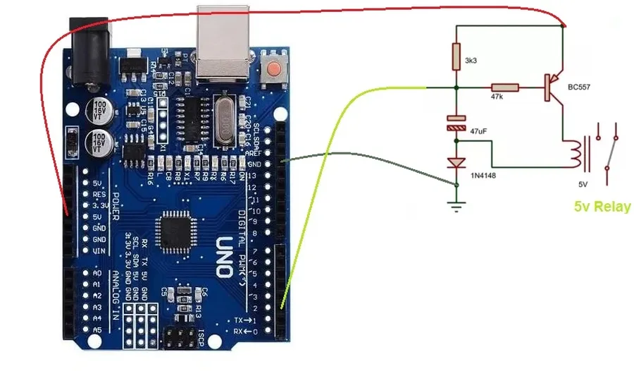
Switching Circuit: The BC557 can act as a switch, controlling power to a load. In this scenario, the transistor is operated in either cutoff or saturation. Applying a base voltage sufficient to drive the transistor into saturation will turn on the load. Conversely, removing or insufficient base voltage will cut off the transistor and turn off the load. A common example is using the transistor to switch a relay or a small DC motor.
Simple Light Activated Switch: A BC557 can be used to create a simple light-activated switch. A photoresistor is used to control base current. In dark conditions the resistance of the photoresistor is high, resulting in low base current, and the transistor turns off. In bright conditions, the resistance drops and sufficient base current flows to turn the transistor on, activating the load.
| Application | Circuit Type | Key Characteristics |
|---|---|---|
| Audio Preamplifier | Common Emitter | High voltage gain, linear amplification |
| Electronic Switch | Saturated/Cutoff | Controls current flow to a load, quick switching |
| Light Activated Switch | Photoresistor Controlled | Automatic switching based on ambient light levels |
It's important to select suitable bias resistors and other components based on specific circuit parameters to ensure correct functionality. Always refer to the BC557 datasheet for maximum voltage and current ratings to avoid damage to the transistor. These examples are a starting point for understanding the practical use of the BC557; the same principle may be adapted for diverse applications by tuning the specific circuit parameters
Troubleshooting Common BC557 Circuit Issues
Diagnosing issues in BC557 transistor circuits requires a systematic approach, considering common failure points and typical application scenarios. This section will guide you through identifying and resolving problems related to biasing, transistor malfunction, and performance deviations.
- Incorrect Biasing
A common cause of circuit malfunction is improper biasing of the BC557. This can lead to the transistor operating in the wrong region, such as saturation or cut-off, instead of the desired active region for amplification. Verify the resistor values in the biasing network against your design requirements and datasheet specifications. Use a multimeter to confirm that the base, collector, and emitter voltages are within the expected operating range. - Transistor Failure
Transistors, especially when subjected to excessive voltage or current, can fail. A failed BC557 can exhibit symptoms such as a short circuit (low resistance between any two pins), an open circuit (no current flow between pins), or a significant change in its electrical characteristics. To test, use a multimeter in diode mode to check the junctions (base-emitter and base-collector). Readings significantly different from expected junction voltages (typically around 0.7V for silicon junctions) indicate a faulty transistor. A replacement will be needed. - Performance Issues
If the BC557 circuit operates, but not to the desired performance, you might be facing problems such as insufficient gain or unwanted oscillations. Verify that components are correctly connected and use an oscilloscope to check signal integrity and confirm that oscillations are absent. Consider the impact of stray capacitance or inductance in your circuit that can affect the signal. - Thermal Considerations
Excessive heat can significantly affect transistor operation and can even lead to permanent damage. Ensure that the BC557 is operating within its maximum power dissipation rating. Consider heatsinking for high power applications and verify heat dissipation in your design. Insufficient heat sinking may cause the transistor to operate erratically or fail due to thermal runaway. - Component Variation
Variations in the electrical characteristics of circuit components, such as resistors, capacitors, and even the transistor itself, can lead to performance discrepancies. Always check component values with a multimeter to confirm that they match the desired values. Check capacitor values are within the tolerance stated on them, and confirm the hFE of the transistor if required for your design.
The BC557 transistor, a small but powerful component, is a cornerstone of modern electronics. From simple switching circuits to complex amplifiers, its versatility makes it an essential part of any electronics enthusiast's toolkit. Understanding its datasheet, equivalents, and practical applications, especially compared to its NPN counterpart, the BC547, empowers you to create more robust and innovative designs. As technology advances, the principles behind the BC557 and its counterparts like BC556 and BC558, will remain vital for future advancements in electronics.