Digital Potentiometers: Revolutionizing Analog Control
In an era where digital control permeates nearly every aspect of our lives, the humble potentiometer, a cornerstone of analog electronics, has undergone a digital transformation. Enter the digital potentiometer (digipot), a device that mimics the functionality of its analog counterpart but with digital precision and control. This article dives deep into the workings of digipots, exploring their applications, advantages over traditional potentiometers, and how they are shaping modern electronics. From adjusting audio levels in your smartphone to controlling the speed of industrial motors, the digital potentiometer has rapidly become indispensable.
What is a Digital Potentiometer?
A digital potentiometer, often called a digipot, is an electronic component that digitally emulates the function of a traditional analog potentiometer. Unlike its mechanical counterpart, a digipot utilizes digital control signals to adjust its resistance, enabling precise and repeatable adjustments through electronic means. This allows for dynamic, software-driven control of resistance in circuits, offering a significant advantage over manual adjustments.
How Digital Potentiometers Work: Internal Structure and Control Mechanisms
Digital potentiometers, or digipots, achieve their variable resistance functionality through an intricate internal structure and digital control mechanisms. Unlike their mechanical counterparts, digipots employ an electronic architecture that precisely emulates potentiometer behavior using digital signals, enabling highly accurate and repeatable resistance settings.
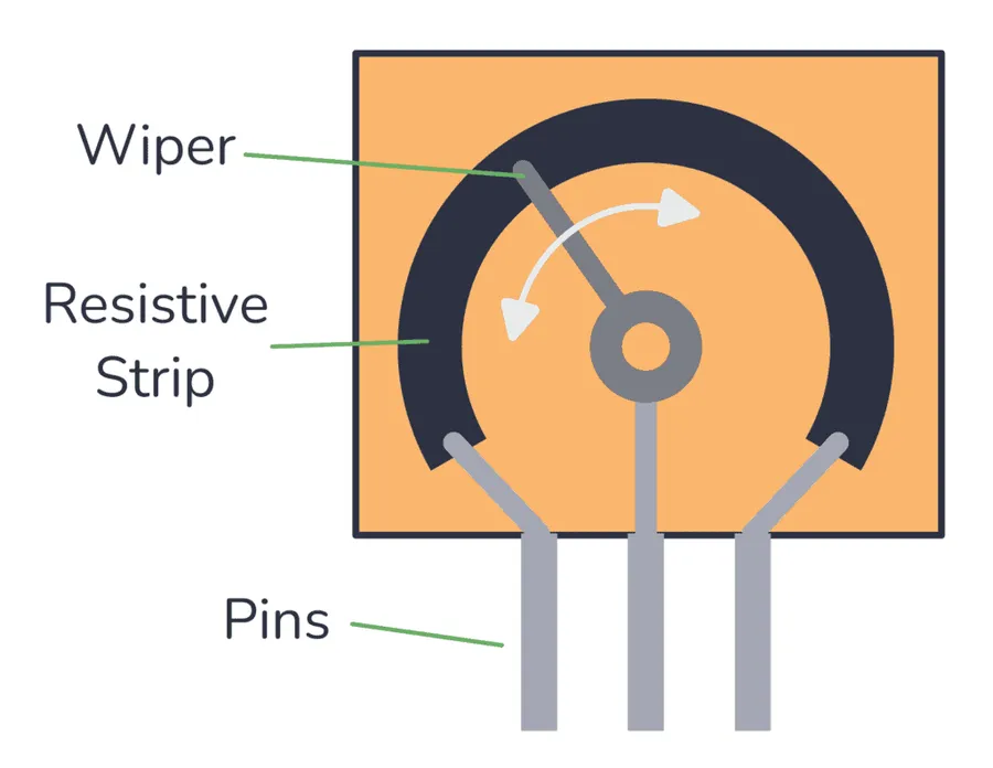
At the core of a digital potentiometer lies a resistor ladder or string. This ladder comprises multiple fixed resistors connected in series, with electronic switches or CMOS transmission gates placed between each resistor and at the tap points of the ladder. These switches, controlled by digital signals from an interface, select the specific connection point along the resistor ladder, determining the effective resistance between the digipot's terminals. The architecture allows for a discrete number of resistance levels, dictated by the number of steps or taps in the resistor ladder.
Digital control is achieved through various communication protocols, with I²C and SPI being the most prevalent. These serial interfaces allow a microcontroller or other digital device to send commands to the digipot, dictating which switches to close, and thus, the resulting resistance. Control logic within the digipot decodes these commands, updating the switches to the desired position. Non-volatile digipots incorporate memory elements to store the position of the wiper arm, preserving its setting even after power is removed.
| Feature | Description |
|---|---|
| Resistor Ladder | Series of fixed resistors forming the resistance path. Allows for discrete resistance settings. |
| Electronic Switches | CMOS transmission gates or similar devices that connect or disconnect sections of the resistor ladder, controlled by digital signals. |
| Digital Interface | Typically I²C or SPI, used for communication with a microcontroller to set the resistance. |
| Control Logic | Decodes digital commands to control switch positions within the resistor ladder. |
| Memory Element (Non-Volatile) | Stores the wiper position for digipots designed to retain settings across power cycles. |
The resolution of a digipot is determined by the number of steps or taps, typically expressed in bits (e.g. 8-bit, 10-bit), and this dictates the granularity of the adjustable resistance. Higher resolution allows for finer adjustments and more precise control of the circuit. The speed of the interface and the settling time of the digipot influence how quickly changes in resistance can be made.
Advantages of Digital Potentiometers Over Analog Potentiometers
Digital potentiometers (digipots) offer significant advantages over their analog counterparts, primarily stemming from their digital control, which enables superior precision, repeatability, and adaptability in modern electronic systems. This leads to enhanced performance, reduced wear, and increased automation capabilities.
| Feature | Analog Potentiometer | Digital Potentiometer |
|---|---|---|
| Control Method | Mechanical (manual) | Digital (electronic) |
| Precision | Limited by mechanical tolerances | High, defined by resolution (e.g., 8-bit, 10-bit) |
| Repeatability | Subject to mechanical wear and variation | Excellent, consistent resistance settings |
| Interface | Directly wired into analog circuits | Digital interfaces (I2C, SPI, etc.) |
| Adjustability | Manual adjustment only | Automated adjustments via digital commands |
| Mechanical Wear | Prone to wear over time | No mechanical wear, extremely durable |
| Integration | Standalone component | Easily integrated with microcontrollers and digital systems |
| Resistance Values | Limited to available component values | Wide range of digitally adjustable values |
Common Applications of Digital Potentiometers
Digital potentiometers are highly versatile components finding extensive use across diverse applications due to their precision and programmability. They provide an electronically controllable resistance, crucial in numerous systems. This section explores some of the key areas where digital potentiometers are implemented, showcasing their practical significance.
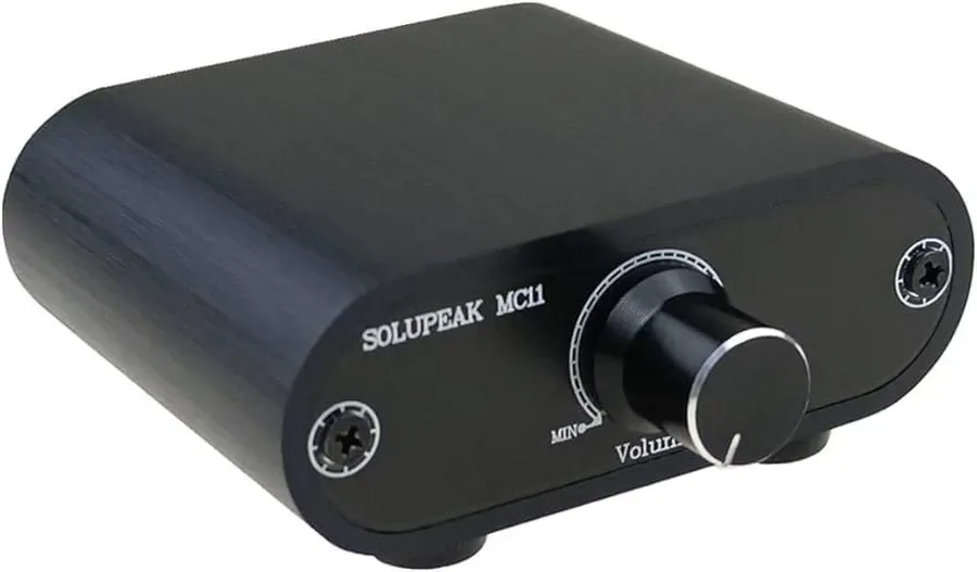
- Audio Equipment: Volume Control and Signal Attenuation
In audio systems, digital potentiometers provide precise volume control and signal attenuation. Unlike traditional mechanical potentiometers which can wear and introduce noise, digital potentiometers offer a clean, digital interface for setting volume levels with high accuracy and repeatability. For example, in digital audio mixers and amplifiers, digipots are used to digitally control the audio signal gain avoiding the mechanical wear and tear associated with analog solutions. - Lighting Control: Dimming and Color Mixing
Digital potentiometers are utilized in lighting systems to achieve precise dimming and color mixing. They allow for software-controlled brightness levels in LEDs, providing smooth transitions and consistent output. For example, in stage lighting or architectural lighting applications, digital potentiometers facilitate dynamic lighting adjustments without manual intervention. This includes advanced color mixing control in RGB and addressable LED systems. - Power Supply Regulation: Voltage and Current Adjustment
In power supply circuits, digital potentiometers enable real-time adjustment of voltage and current outputs. This fine control is crucial in laboratory equipment, battery chargers, and other power-sensitive applications. For example, a digipot can be used to dynamically adjust the feedback network in a switching regulator to alter its output voltage, making it easily configurable or even automated in test environments. - Industrial Automation: Process Control and Calibration
Digital potentiometers are essential in industrial automation for process control and calibration tasks. They enable remote adjustment of parameters, ensuring precise control over manufacturing processes and equipment. For instance, digipots are used for calibrating sensors, adjusting motor speeds, and controlling the position of robotic arms, thereby optimizing manufacturing efficiency and precision. - Sensor Calibration: Offset and Gain Adjustment
Many sensors require calibration for accurate readings, and digital potentiometers facilitate this by allowing for precise offset and gain adjustments. This can be done remotely through a digital interface, which is particularly beneficial for sensors deployed in inaccessible locations. In applications from environmental monitoring to medical devices, these adjustments ensure consistent, high-precision performance.
Digital Potentiometer Types and Key Specifications
Digital potentiometers, or digipots, offer a versatile alternative to their mechanical counterparts, but understanding their various types and specifications is crucial for effective implementation. These electronic components are available in several configurations, each with unique attributes that determine their suitability for specific applications.
| Feature | Volatile Digital Potentiometers | Non-Volatile Digital Potentiometers |
|---|---|---|
| Data Retention | Resistance setting lost when power is removed. | Resistance setting retained when power is removed. |
| Memory Type | Typically utilizes SRAM or a similar temporary storage. | Employs EEPROM, Flash, or similar non-volatile memory. |
| Use Cases | Applications where settings are frequently adjusted or where the loss of setting isn't critical (e.g., audio volume). | Applications requiring settings to be preserved after power cycles (e.g., calibration, bias settings). |
| Cost | Generally less expensive due to simpler memory. | Generally more expensive due to more complex memory. |
Beyond volatility, key specifications of digital potentiometers include resistance range, tap points, and resolution. Common resistance ranges include 10 kΩ, 50 kΩ, and 100 kΩ, allowing flexibility in circuit design. Tap points, or the number of discrete resistance steps available, directly impact the adjustment granularity. Resolution, often expressed in bits, defines the precision of resistance adjustment with higher bit resolution allowing for finer control. For example an 8-bit device will have 256 discrete steps between its lowest and highest resistance values. Other critical performance metrics include the end-to-end resistance tolerance, temperature coefficient, and bandwidth.
Selecting the appropriate digital potentiometer hinges on carefully considering these specifications against the requirements of the specific application. Higher resolution is imperative for fine tuning, while non-volatile memory is crucial for applications that require retention of set values during power loss. A good practice is to look for digital potentiometer with a tolerance rating less than 1%, since these are more accurate and precise.
Integrating a Digital Potentiometer into your Project
Integrating a digital potentiometer into an electronic project, while seemingly complex, is straightforward when approached systematically. The key lies in understanding the digipot's communication protocol and ensuring the correct interfacing with a microcontroller.
Primarily, digipots communicate via serial interfaces such as SPI or I²C. Selecting the correct interface for the application is crucial. SPI is generally faster while I²C requires fewer pins. A thorough review of the datasheet for the specific digital potentiometer in use will define these characteristics.
Here’s a step-by-step guide to help with integration:
- Select a Compatible Digipot
Choose a digital potentiometer with a resistance range and interface (SPI or I2C) that suits your application requirements. Consider parameters like resolution (number of taps) and voltage tolerance. Example digipots are manufactured by Analog Devices, Microchip, and Maxim Integrated. - Review the Datasheet
Carefully read the manufacturer's datasheet. It specifies the pinout, voltage requirements, control commands and communication protocols. It is the most important reference document. - Circuit Connections
Connect the digital potentiometer to your circuit according to the datasheet. This includes power supply, ground, and communication lines (SCL/SDA for I²C, or SCK/MOSI/MISO/CS for SPI). Ensure correct signal levels and polarity. - Microcontroller Interface
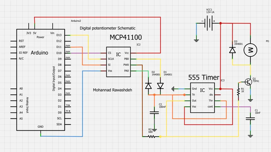
Connect the digipot's communication lines to the appropriate pins of your microcontroller (e.g., Arduino, ESP32, Raspberry Pi). Ensure any necessary pull-up resistors are implemented for I²C as per the datasheet recommendations. - Software Implementation
Use the libraries and example code provided in the digipot datasheet or other reputable sources. For Arduino, libraries for SPI and I2C are readily available, simplifying interaction with the digital potentiometer. The control code typically requires initialization, resistance setting, and reading current resistance values. It is important to understand the bit-level control commands, specifically, the correct addressing and command sequences to send the digital pot to specific levels. - Testing and Calibration
After implementation, use a multimeter to verify the functionality by comparing the programmed resistance value to the measured value. If required, perform calibration to account for any device variation or component tolerance. Always check to ensure the digipot has achieved the expected and intended resistance value.
By carefully adhering to these guidelines, you should be able to integrate a digital potentiometer effectively into your electronic project. Remember to refer to manufacturer datasheets for specific details for the selected device.
Frequently Asked Questions about Digital Potentiometers
This section addresses common queries regarding digital potentiometers, providing clear and concise answers to enhance understanding and application of these versatile electronic components. It covers the fundamental differences between digipots and digital rheostats, usage guidelines, and insights into popular models.
- What exactly is a digital potentiometer?
A digital potentiometer, often called a digipot, is an electronic component that mimics the function of a mechanical potentiometer, but its resistance is controlled digitally rather than manually. It uses digital signals to adjust the resistance between two terminals, allowing for precise and repeatable adjustments through a microcontroller or other digital interfaces. - How does a digital potentiometer differ from a digital rheostat?
The primary difference lies in how they're used within a circuit. A digital potentiometer provides a variable voltage divider, with three terminals acting as two fixed terminals and a wiper. A digital rheostat, on the other hand, typically only uses two terminals, and is used to vary the resistance within a single path of the circuit, often in series with another component. - What are some common ways to control a digital potentiometer?
Digital potentiometers are primarily controlled via digital interfaces such as SPI (Serial Peripheral Interface) and I2C (Inter-Integrated Circuit). These interfaces allow microcontrollers and other digital devices to send specific commands that adjust the digipot's resistance setting. Some potentiometers also use simpler up/down control signals. - What are some common resistance values of digital potentiometers?
Common resistance values for digital potentiometers include 1kΩ, 10kΩ, 50kΩ, and 100kΩ. The selection of the resistance value will depend on the intended application, the voltage and current requirements of the circuit, and the required range of adjustment. - What are the key advantages of using digital potentiometers compared to mechanical potentiometers?
Digital potentiometers offer several benefits over their mechanical counterparts. These include higher precision and repeatability of resistance settings, lack of mechanical wear and tear, the ability to be controlled remotely through digital interfaces, easy automation of adjustments, and smaller physical size. - What are some popular applications for digital potentiometers?
Digital potentiometers find widespread use in applications like audio volume control, lighting dimming, LCD contrast adjustment, programmable power supplies, sensor calibration, and industrial process control where precision and automated adjustment are crucial. - What should one consider when selecting a digital potentiometer for a project?
Key considerations include the required resistance range, the resolution (number of steps), the type of interface (SPI, I2C, or up/down signals), the operating voltage, the power consumption, the tolerance of the resistance value, and whether non-volatile memory for retaining resistance settings is needed. The temperature coefficient of resistance should also be considered for demanding applications.
Future Trends in Digital Potentiometer Technology

The evolution of digital potentiometer technology is driven by the increasing demands for smaller, more efficient, and highly precise electronic components. Future trends point towards significant advancements in several key areas, pushing the boundaries of what's currently achievable.
These trends are not isolated but interconnected. For instance, advancements in materials science will enable smaller form factors and lower power consumption, while progress in signal processing will improve accuracy and enable new functionalities. These advancements will expand the scope of applications for digital potentiometers, further solidifying their role in modern electronics.
- Miniaturization
Future digipots will continue to shrink in size, driven by the demand for compact devices and the advancements in microfabrication techniques. Expect to see increasingly smaller packages, allowing integration into space-constrained applications and contributing to reduced device footprints. - Lower Power Consumption
As energy efficiency becomes more critical, future digipots will be engineered for significantly lower power consumption, making them suitable for portable and battery-powered devices. This includes reduced quiescent current and lower operating voltages. - Enhanced Accuracy and Resolution
Expect to see digital potentiometers with higher resolution, allowing for more precise control over resistance. Additionally, advancements in manufacturing and control techniques will improve linearity and reduce errors, leading to enhanced accuracy and more stable performance. - Advanced Materials
The development and application of new materials will enable improved performance metrics, including higher temperature tolerances, reduced resistance drift, and better reliability. These new materials may also enable new fabrication techniques for smaller devices. - Integration with Communication Protocols
Future digital potentiometers will see better integration with standard communication protocols, such as I3C, allowing for more efficient data transmission and device control in complex systems. - Emerging Applications
The innovations in digipot technology will lead to new and expanding applications. These include adaptive and intelligent circuits, sensor calibration, wearable technology, medical implants, and advanced robotics, all leveraging the advantages of precise and dynamically adjustable resistance.
The digital potentiometer represents a significant leap forward from its analog predecessor, offering superior precision, control, and integration capabilities. From simple audio volume control to complex industrial automation systems, digipots are transforming how we interact with electronics. As technology continues to advance, the versatility and impact of digital potentiometers are set to expand, making them an indispensable component in the future of electronic control. Understanding how to leverage their capabilities will be key for any forward-thinking engineer or maker seeking to build the next generation of digital products.