Mastering Resistors, Capacitors, and Inductors: A Practical Guide
In the realm of electronics, much like the diverse roles in a symphony orchestra, resistors, capacitors, and inductors each play a distinct yet crucial part. Resistors control current flow, much like the volume control of the music; capacitors store energy, similar to the pause in a song; and inductors oppose changes in current, like the tempo of a melody. Understanding these fundamental components is key to mastering electronics, allowing us to build everything from basic circuits to complex electronic systems. This article will delve into each component, explore their properties, and illustrate how they work together in harmony.
Resistors: Controlling the Flow of Electricity
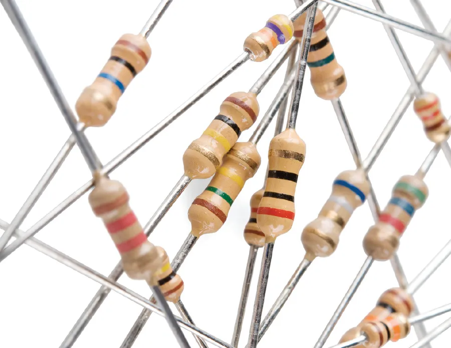
Resistors are fundamental passive electronic components designed to impede the flow of electrical current within a circuit. They achieve this by converting electrical energy into heat, effectively limiting the current and enabling precise control over voltage levels. The core function of a resistor is defined by its resistance value, measured in ohms (Ω), which dictates the magnitude of current flow restriction. This capability makes resistors indispensable in a vast array of electronic applications.
Resistors come in various types, each tailored for specific applications and performance requirements. Fixed resistors offer a set resistance, while variable resistors, also known as potentiometers, allow for manual adjustment of the resistance. Factors influencing the resistance value include the resistor’s material, length, cross-sectional area, and temperature. Precise resistance values can be identified through the resistor color code, a standardized system of colored bands that correspond to specific resistance values and tolerances.
- Fixed Resistors
These resistors have a single, unchangeable resistance value. They are the most common type of resistor. - Variable Resistors (Potentiometers)
Also known as potentiometers, these allow for manual adjustment of the resistance value through a wiper or slider, used for volume control, calibration, and other applications. - Factors Influencing Resistance Value
The resistance of a resistor is determined by the material, length, and cross-sectional area of the resistive element, in addition to the temperature of operation, described by the relationship R = ρL/A, where R is the resistance, ρ is the resistivity of the material, L is the length of the conductor, and A is the cross sectional area. - Resistor Color Coding
The color code consists of colored bands that indicate the resistance value, tolerance, and temperature coefficient of the resistor. This is a standardized way to quickly identify the electrical properties of the resistor, especially when the component size makes direct marking unfeasible.
| Resistor Type | Description | Application Examples |
|---|---|---|
| Fixed Resistor | Offers a constant resistance value. | Current limiting in LEDs, voltage dividers |
| Variable Resistor | Allows manual adjustment of the resistance value. | Volume controls, calibration circuits |
Capacitors: Storing Electrical Energy
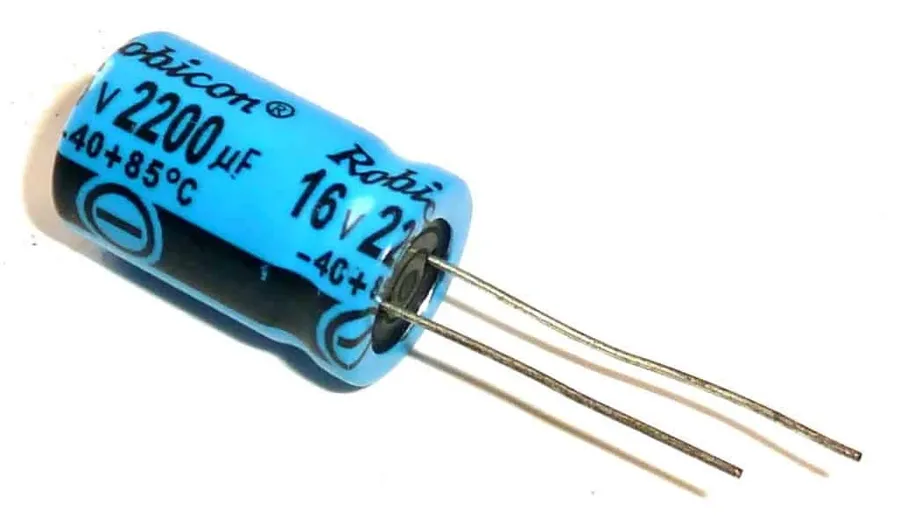
Capacitors are fundamental electronic components that store energy electrostatically in an electric field, making them crucial for various circuit functions. Unlike resistors, which impede current flow, capacitors temporarily hold charge, enabling filtering, decoupling, timing, and energy storage applications. The ability of a capacitor to store charge is quantified by its capacitance, measured in farads (F).
Capacitors come in various types, each with specific characteristics that determine their suitability for different applications. Key types include:
- Ceramic Capacitors
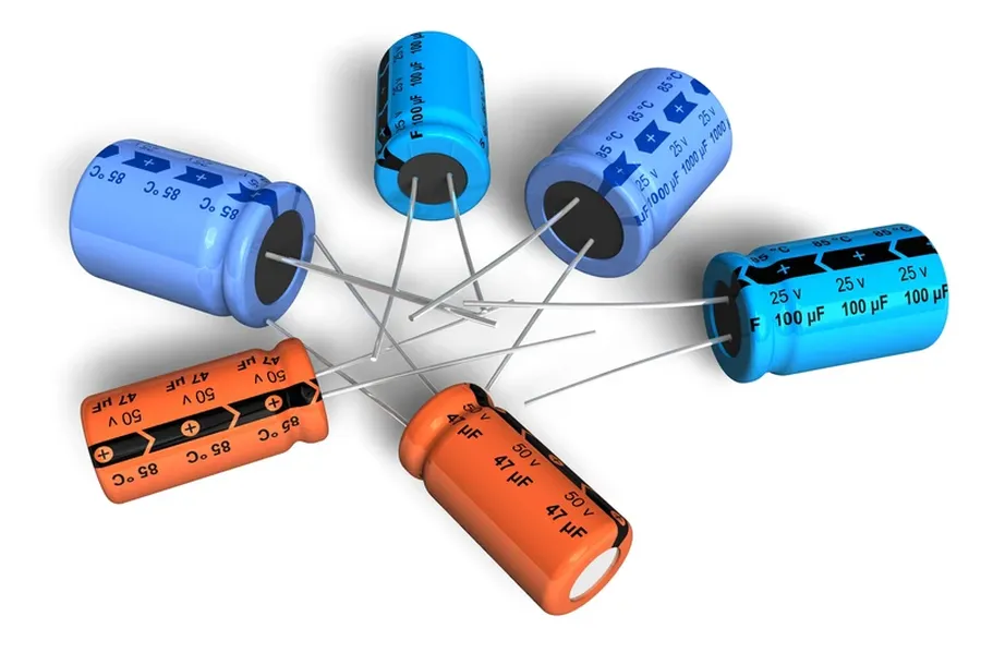
These are non-polarized, compact, and inexpensive, suitable for general-purpose applications like bypass and coupling. They are available in a wide range of values and sizes. - Electrolytic Capacitors
These capacitors offer high capacitance values in small packages, making them ideal for power supply filtering and decoupling. They are polarized, requiring proper orientation in a circuit. - Tantalum Capacitors
These are known for their high stability and reliability, often used in high-performance applications. Like electrolytic capacitors, they are polarized. - Film Capacitors
These capacitors are known for their stability and low loss, suitable for audio and high-frequency applications. They are non-polarized, offering versatility in circuit design.
Capacitor behavior differs significantly between direct current (DC) and alternating current (AC) circuits:
- DC Circuits
In a DC circuit, a capacitor initially acts as a short circuit, allowing current to flow as it charges. Once fully charged, the capacitor acts as an open circuit, blocking DC current. - AC Circuits
In an AC circuit, a capacitor's impedance (opposition to current flow) decreases as the frequency increases. This property is leveraged in filtering and signal processing applications, where capacitors allow AC signals to pass while blocking DC.
Capacitance is determined by several factors, including:
- Plate Area
Larger plate areas result in higher capacitance. - Distance between Plates
Smaller distances between plates increase capacitance. - Dielectric Material
The type of dielectric material between the plates influences capacitance; materials with higher permittivity increase capacitance.
Capacitance (C) is calculated using the formula: C = ε * (A / d), where ε is the permittivity of the dielectric material, A is the plate area, and d is the distance between the plates. Understanding this formula is crucial for selecting the appropriate capacitor for a specific application and determining how different parameters affect its behavior.
Inductors: Opposing Changes in Current
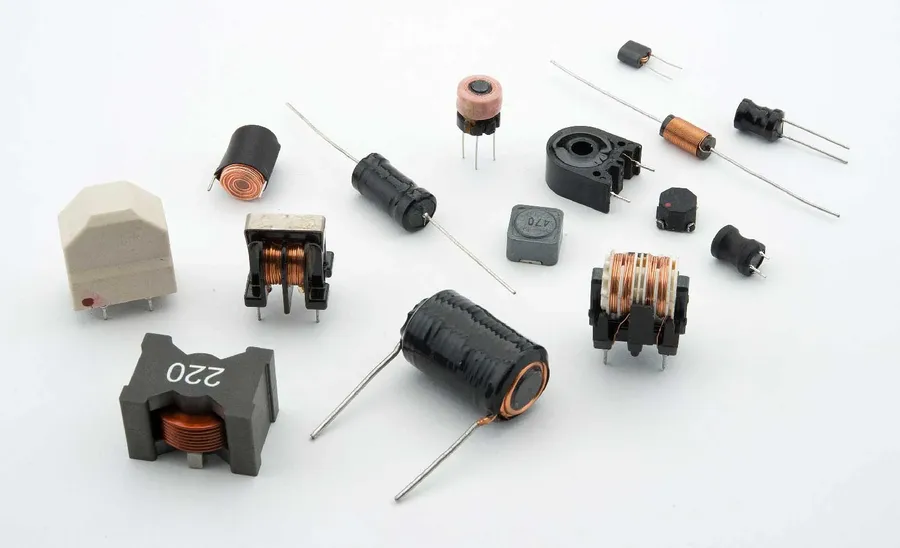
Inductors are fundamental passive electronic components that store energy in a magnetic field when an electric current flows through them. Unlike resistors which impede current flow, inductors oppose *changes* in current. This property, known as inductance, is measured in henries (H) and is central to their varied applications in electronic circuits.
Inductors find applications in diverse fields due to their ability to store and release energy. This makes them crucial for tasks such as filtering, where they can block or allow certain frequencies, in tuning circuits, where they are used to select a frequency and in energy conversion. The following sections will provide more detail on inductor types, behavior in AC and DC circuits and inductance calculation.
| Characteristic | Description |
|---|---|
| Energy Storage | Stores energy in a magnetic field created by current flow. |
| Opposition to Current | Opposes *changes* in current flow, not current flow itself. |
| Inductance (L) | Measured in Henries (H). Determines the extent to which an inductor opposes changes in current. |
| Behavior in DC Circuits | Acts as a short circuit after the initial transient period; only the internal resistance of the coil limits the current once the circuit has stabilized. |
| Behavior in AC Circuits | Impedance increases with frequency, effectively blocking higher frequencies. Reactance is the term used to describe this opposition in AC. |
Inductors come in a variety of types, each tailored for specific applications. The main differentiation is the core material used and the coil construction. The choice of core material influences the inductance value and the overall inductor performance. Some of the common types include:
- Air-Core Inductors
These inductors have no ferromagnetic core material. They are typically used in high-frequency applications where core losses need to be minimized. They offer good linearity but have relatively low inductance values for their size. - Ferrite-Core Inductors
Ferrite cores offer high permeability, enabling higher inductance values compared to air-core inductors for the same physical dimensions. They are commonly used in lower-frequency applications and power electronics. - Iron-Core Inductors
Iron-core inductors are generally used in low-frequency applications, such as power supply filtering. They are typically laminated to reduce eddy current losses and are designed to handle relatively high currents. - Toroidal Inductors
Toroidal inductors feature a core in the shape of a toroid (donut), allowing for a concentrated magnetic field and minimizing external magnetic field interference. They are often used in sensitive circuits and filters.
The inductance (L) of a coil can be calculated using the following simplified formula:
L = \frac{N^2 \mu A}{l}
Where: - L is the inductance in Henries (H). - N is the number of turns of wire. - μ is the permeability of the core material. - A is the cross-sectional area of the core. - l is the length of the coil. It is important to note that this is a simplified formula and is based on an ideal inductor. In reality, the physical characteristics and the non-ideal properties of materials will affect the value of the calculated inductance.
The Interplay Between Resistors, Capacitors, and Inductors
Resistors, capacitors, and inductors, while distinct in their individual functions, exhibit a complex and crucial interplay when combined in electrical circuits. Their interactions form the bedrock of numerous electronic applications, enabling functions from simple filtering to complex signal processing. Understanding their combined behavior is paramount for effective circuit design.
In series circuits, the total impedance is the sum of the individual impedances of each component, while in parallel circuits, the total impedance is the reciprocal of the sum of the reciprocals of each component's impedance. This results in varying current and voltage distributions across different combinations, giving rise to diverse circuit behaviors and functionalities.
| Circuit Configuration | Resistor Behavior | Capacitor Behavior | Inductor Behavior | Overall Effect |
|---|---|---|---|---|
| Series | Limits current, voltage drops proportionally to resistance | Blocks DC, impedance decreases with frequency, voltage is divided inversely to impedance | Opposes changes in current, impedance increases with frequency, voltage is divided inversely to impedance | Impedance increases, overall current decreases |
| Parallel | Limits current, current is divided inversely to resistance | Passes AC, impedance decreases with frequency, current is divided proportionally to impedance | Passes DC, current is divided proportionally to impedance, impedance decreases with frequency | Impedance decreases, overall current increases |
The interplay of resistors, capacitors, and inductors is not limited to simple series or parallel connections. Complex circuits may combine these components in various configurations to achieve specific frequency response characteristics, filtering capabilities, and timing control. For instance, an RLC circuit combines resistors, capacitors, and inductors to create resonant circuits used in radio tuners, filters, and oscillators.
In signal processing, combinations of resistors and capacitors or inductors are used in filters for frequency selection to remove unwanted components of a signal. Furthermore, in timing circuits, the controlled charging or discharging of a capacitor through a resistor provides a predictable timing function, which is a cornerstone of countless digital electronics. The combined usage is the foundation for sophisticated circuits that perform filtering, timing, and signal processing.
Practical Applications of Resistors, Capacitors, and Inductors
Resistors, capacitors, and inductors, while fundamental, manifest in diverse applications spanning across numerous electronic systems. Their interplay is crucial in shaping how electronic devices operate, providing the basis for critical functionalities like power delivery, signal processing, and energy storage. This section explores the practical implications of these components in real-world scenarios.
- Power Supply Smoothing
Capacitors, in conjunction with resistors, are essential for smoothing the output of power supplies. A fluctuating DC input is filtered by a capacitor acting as a buffer that stores energy and releases it when the voltage drops, while resistors help limit the current. This reduces ripple and noise to provide a stable DC voltage for sensitive circuits. - Signal Filtering
In audio equipment, capacitors and inductors are used to construct filters that separate high-frequency and low-frequency components of an audio signal. For example, capacitors block DC and low-frequency signals, allowing high-frequency signals to pass, a function crucial in audio amplifiers. Inductors achieve the opposite effect, blocking high frequencies. This allows for the isolation of desired frequencies or the reduction of unwanted noise. - Energy Storage in Power Inverters
Inductors and capacitors play a pivotal role in power inverters, which convert DC power to AC power, for applications such as renewable energy systems or uninterruptible power supplies. Inductors store magnetic energy and capacitors store electrical energy, used as temporary storage while the inverter switches. Inverters require accurate timing and minimal energy loss, enabled by the specific characteristics of inductors and capacitors. - Timing Circuits
Resistors and capacitors work together to form RC circuits which are the basis of timing circuits. The charge and discharge time of a capacitor in series with a resistor is predictable, making them ideal for applications that require a precise time delay, such as oscillators and timers in electronic control systems. - Tuning Circuits
Inductors and capacitors form LC circuits which are used in resonant circuits used to filter specific frequencies. These circuits are central to wireless communication and radio circuits, which use tunable LC tank circuits to filter specific radio frequencies.
| Application | Component(s) Used | Function |
|---|---|---|
| Power Supply Smoothing | Capacitors, Resistors | Reduces voltage ripple; provides stable DC output |
| Audio Signal Filtering | Capacitors, Inductors | Separates high and low frequencies; removes unwanted noise |
| Power Inverters | Inductors, Capacitors | Energy storage and filtering for DC to AC conversion |
| Timing Circuits | Resistors, Capacitors | Provides predictable time delay in circuits |
| Tuning Circuits | Inductors, Capacitors | Filters a narrow band of frequencies for selective reception |
Frequently Asked Questions About Resistors, Capacitors, and Inductors
This section addresses common inquiries regarding resistors, capacitors, and inductors, clarifying their distinctions, behavior, applications, and energy storage mechanisms, thus providing a comprehensive understanding of these fundamental electronic components.
- What are the fundamental differences between resistors, capacitors, and inductors?
Resistors impede current flow by converting electrical energy into heat, capacitors store energy in an electric field and block DC current, and inductors store energy in a magnetic field and resist changes in current. These fundamental differences define their distinct roles in electronic circuits. - How do resistors, capacitors, and inductors behave in DC circuits?
In DC circuits, resistors exhibit constant resistance, limiting current flow proportionally to voltage. Capacitors act as open circuits after being fully charged, blocking DC current. Inductors act as short circuits allowing DC current to flow unimpeded, after the initial surge, because there are no changes in current. - How do resistors, capacitors, and inductors behave in AC circuits?
In AC circuits, resistors exhibit the same resistance as in DC circuits. Capacitors impede AC current flow with a reactance that is inversely proportional to frequency, blocking low frequency AC signals. Inductors impede AC current flow with a reactance that is directly proportional to frequency, blocking high frequency AC signals. - What are some typical applications for resistors, capacitors, and inductors?
Resistors are used for current limiting, voltage division, and biasing. Capacitors are employed in filtering, smoothing, decoupling, and timing circuits. Inductors are found in filtering, tuning, energy storage, and electromagnetic compatibility (EMC) applications. - How do these components store and release energy?
Capacitors store energy by accumulating charge on their plates, which creates an electric field between them. This energy is released when the capacitor discharges. Inductors store energy in a magnetic field created by the current flowing through them. This energy is released when the magnetic field collapses due to a change in current. Resistors do not store energy but dissipate it as heat. - What is the relationship between resistance, capacitance, inductance and frequency?
Resistance remains constant with changes in frequency. Capacitive reactance is inversely proportional to frequency, implying that at higher frequencies, a capacitor's opposition to AC current decreases. Inductive reactance is directly proportional to frequency, indicating that at higher frequencies, an inductor's opposition to AC current increases. - Why are these three components considered fundamental in electronics?
Resistors, capacitors, and inductors are fundamental due to their unique and complementary behaviors. They form the basis of most electronic circuits and systems by allowing the control and manipulation of electrical signals and energy. Their interplay enables functions like signal processing, power conversion, and many others.
Selecting the Right Resistors, Capacitors, and Inductors: A Practical Guide
Selecting appropriate resistors, capacitors, and inductors is crucial for optimal circuit performance. This section provides practical guidance on choosing the correct component values, considering factors such as tolerances, voltage ratings, standard sizes, and how to interpret component markings and datasheets.
When selecting components, it’s important to have a clear understanding of the application requirements. This includes aspects like operating voltage, current, frequency and the environment it will operate in. This is a fundamental step before diving into selecting specific components.
The selection process involves evaluating component specifications and ensuring the device is suitable for your design requirements. We will delve into some specific details for each component type.
| Component | Key Selection Criteria | Considerations |
|---|---|---|
| Resistor | Resistance Value, Power Rating, Tolerance | Temperature Coefficient, Size, Type (Fixed, Variable, SMD) |
| Capacitor | Capacitance Value, Voltage Rating, Tolerance | Dielectric Material (Ceramic, Electrolytic, Tantalum), ESR, Temperature Stability, Size, Polarization |
| Inductor | Inductance Value, Current Rating, DC Resistance | Core Material (Air-Core, Ferrite), Saturation Current, Quality Factor (Q), Size, Shielding |
Understanding component datasheets is a critical skill for any engineer. These datasheets contain comprehensive specifications, operating characteristics and test data, which will assist in proper component selection. Here is a basic explanation:
- Component Type:
Identifies whether it is a resistor, capacitor, or inductor, including its subtype. - Electrical Characteristics:
Includes the primary electrical parameters such as resistance (Ω), capacitance (F), or inductance (H) along with tolerances. - Voltage and Current Ratings:
Specifies the maximum voltage and current that the component can handle safely. - Temperature Specifications:
Details the operating temperature range and temperature coefficient, which indicates how the component's characteristics change with temperature. - Physical Dimensions and Size:
Provides details about the component's dimensions and package size, which is critical for proper PCB layout. - Material and Construction:
Describes the materials used in component fabrication and how it's constructed, which influences performance and reliability. - Environmental Compliance:
Lists compliance information and certifications regarding material content, such as RoHS.
Additionally, it's important to understand industry-standard sizes and markings. For example, SMD (Surface Mount Device) resistors and capacitors often come in standardized package sizes like 0603, 0805, and 1206. Resistors utilize color codes or numerical markings to denote resistance, and sometimes voltage. Similarly, capacitors have markings that indicate their capacitance, voltage rating and sometimes temperature tolerance. Datasheets will explain this in detail if you are unfamiliar with a specific device or brand.
Troubleshooting Circuits with Resistors, Capacitors, and Inductors
Effective troubleshooting of circuits containing resistors, capacitors, and inductors requires a systematic approach, combining component testing with circuit analysis. This section provides practical methods for diagnosing common faults, including open and shorted components, and outlines strategies for fault isolation and repair, ensuring circuit functionality and reliability.
- Testing Resistors
To verify a resistor's integrity, use a digital multimeter (DMM) in resistance mode. Measure the resistance across the resistor terminals. The measured value should match the resistor's nominal value within its tolerance. An open resistor will display infinite resistance, while a shorted resistor will read close to zero ohms. When testing in-circuit, consider the parallel resistance from other components, which can influence the reading. Best practice is to measure resistors out of circuit. - Testing Capacitors
Capacitor testing involves using a DMM with a capacitance measurement function. For a preliminary test, check for shorts by observing the resistance reading; a healthy capacitor should show a high resistance reading initially that slowly increases towards an open circuit reading. Measure the capacitance across the capacitor terminals. A significantly lower reading than the nominal capacitance indicates degradation. A reading of zero or very low resistance indicates a shorted capacitor. Electrolytic capacitors can also be tested for excessive equivalent series resistance (ESR) with a specialized ESR meter, a high ESR indicates degradation. Testing capacitors in-circuit can give incorrect values, therefore, it is often necessary to disconnect one leg of the capacitor from the circuit to measure correctly. - Testing Inductors
To evaluate an inductor, start by using a DMM to measure its DC resistance which should be low, a high resistance or infinite resistance indicates a open inductor. An inductor meter or LCR meter is ideal for measuring inductance and can be used for more accurate evaluation. Shorted inductors will show a very low DC resistance. Inductance values can be affected by in-circuit components, so whenever possible it's best to remove the component from the circuit when testing.
- Common Failure Modes
Resistors typically fail by going open due to overheating or physical damage. Capacitors can fail by shorting due to dielectric breakdown, loss of capacitance due to aging or drying out and an increase in ESR. Inductors mainly fail by opening due to wire breakage or shorting due to insulation failure and consequent inter-winding shorts. - Fault Isolation Techniques
Begin by visual inspection for damaged components or signs of overheating, a blown up capacitor for instance. Use a DMM to measure voltages at key points in the circuit. By systematically measuring voltages and comparing them with the expected values, one can narrow down the faulty section. Component substitution is a powerful technique, replacing a suspect component with a known good component to confirm a diagnosis. Understanding how the circuit functions and the expected behaviour is essential for efficient troubleshooting.
Just as different instruments harmonize in an orchestra, resistors, capacitors, and inductors work together in electronic circuits to achieve a vast range of functionalities. Understanding the individual characteristics and interactions of resistors, which control current, capacitors, which store energy in an electric field, and inductors, which store energy in a magnetic field, is essential for anyone venturing into electronics. With this knowledge, you can now start designing, building, and troubleshooting circuits with confidence, opening the door to exciting possibilities in the world of electronics and beyond.