Mastering Resistors in Parallel: A Comprehensive Guide

In the intricate world of electronics, resistors are fundamental components that control the flow of current. While a single resistor can manage current in a simple circuit, combining multiple resistors in parallel offers unique advantages, enabling us to achieve specific resistance values and distribute current across different paths. This article will navigate you through the fascinating aspects of parallel resistors, exploring their definition, calculation, practical uses, and common troubleshooting tips, providing a deep dive into both the theoretical concepts and real-world applications of resistors in parallel, in a language that's easy to understand.
Understanding Parallel Resistor Circuits
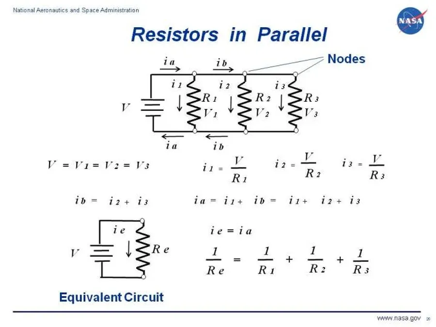
A parallel resistor circuit is characterized by components connected across the same two electrical nodes, creating multiple paths for current flow. This arrangement contrasts with series circuits, where components are connected end-to-end, forming a single path. In parallel circuits, the voltage across each resistor is identical, whereas the current divides between the different paths.
Key characteristics of parallel circuits:
- Shared Nodes
Resistors are connected at both ends to the same two points in the circuit. - Equal Voltage
The voltage drop is the same across all resistors in parallel. - Current Division
The total current entering the parallel connection is distributed across the branches.
The Formula for Calculating Equivalent Resistance
The equivalent resistance of resistors in a parallel circuit is not calculated by a simple sum; rather, it requires a reciprocal calculation. This method accounts for the fact that adding more parallel paths actually *decreases* the overall resistance of the circuit, allowing more current to flow. The standard formula provides a precise means to determine the aggregate effect of these multiple conductive pathways.
The general formula for calculating the total equivalent resistance (R_eq) of resistors connected in parallel is given by:
1/R_{eq} = 1/R_1 + 1/R_2 + 1/R_3 + ... + 1/R_n
Where:
- R_eq
is the equivalent resistance of the entire parallel network. - R_1, R_2, R_3,...R_n
are the individual resistances of each resistor in the parallel circuit. 'n' is the total number of parallel resistors.
This formula requires taking the reciprocal of each individual resistance, summing these reciprocals, and then taking the reciprocal of that sum to find the equivalent resistance.
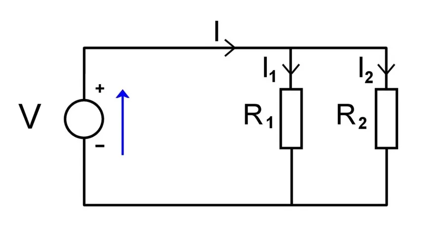
Applying this to a circuit with two resistors, R1 and R2, the formula becomes:
1/R_{eq} = 1/R_1 + 1/R_2
To find R_eq, you must calculate:
R_{eq} = 1 / (1/R_1 + 1/R_2)
Or, a more simplified formula (product over sum) will be covered in the next section, applicable only to two resistors in parallel.
A key observation is that the equivalent resistance (R_eq) will always be *smaller* than the smallest individual resistance in the parallel network. This is because each additional parallel path provides another route for current to flow, which effectively lowers the overall impedance to current.
Simplified Formula for Two Resistors in Parallel
While the general reciprocal formula effectively calculates the equivalent resistance of any number of parallel resistors, a simplified "product-over-sum" formula offers a more direct approach when dealing specifically with two resistors in parallel. This formula is derived directly from the general formula, streamlining calculations and making it more convenient for quick analysis and practical applications.
The simplified formula is expressed as:
R_{eq} = \frac{R_1 \times R_2}{R_1 + R_2}
Where:
- R_eq
is the equivalent resistance of the two parallel resistors. - R1
is the resistance of the first resistor. - R2
is the resistance of the second resistor.
This formula is derived from the general reciprocal formula for parallel resistors: 1/Req = 1/R1 + 1/R2. By finding a common denominator and inverting the result, we obtain the product-over-sum formula. For example, if R1 = 10 ohms and R2 = 20 ohms, Req = (10*20)/(10+20) = 200/30 = 6.67 ohms.
| Feature | General Formula (for n resistors) | Simplified Formula (for 2 resistors) |
|---|---|---|
| Formula | 1/Req = 1/R1 + 1/R2 + ... + 1/Rn | Req = (R1 * R2) / (R1 + R2) |
| Applicability | Applies to any number of parallel resistors | Specifically for two parallel resistors |
| Calculation Steps | Requires multiple reciprocal operations and a final inversion | Directly calculates equivalent resistance using product and sum |
| Complexity | More complex, especially for more than two resistors | Simpler, fewer steps to calculate |
| Use Cases | General case, used when calculating with three or more parallel resistors | Ideal for quick calculations when working with two parallel resistors |
The product-over-sum formula is particularly useful in situations where you are quickly trying to determine the equivalent resistance of two resistors, such as during circuit design or troubleshooting. It offers a quicker, more convenient method than the general reciprocal formula, especially if you're doing manual calculations.
Current and Voltage Distribution in Parallel Circuits
In a parallel circuit, the voltage across each resistor is identical, while the total current from the source is divided among the different branches. This division is inversely proportional to the resistance of each branch, meaning lower resistance branches carry more current. Understanding this behavior is crucial for analyzing and designing parallel resistor circuits.
Key characteristics of current and voltage distribution in parallel circuits:
- Voltage
The voltage across each parallel resistor is the same and equal to the source voltage. This is a fundamental principle of parallel circuits. Mathematically, if V is the source voltage, then V_R1 = V_R2 = V_R3 = ... = V. - Current Division
The total current (I_total) entering a parallel junction splits across different branches. The current through each branch (I_Rx) is inversely proportional to the resistance of that branch, expressed as I_Rx = V / R_x. This means that branches with lower resistance will carry more current. - Kirchhoff's Current Law (KCL)
The sum of the currents entering a node (junction) equals the sum of the currents leaving that node. In a parallel circuit, the total current equals the sum of the branch currents: I_total = I_R1 + I_R2 + I_R3 + ... + I_Rn
Ohm's Law plays a key role in quantifying the current through each resistor. Ohm's Law states that V=IR, where V is the voltage, I is the current, and R is the resistance. Using this law, we can determine the current through a particular branch with the formula I_Rx = V/R_x, knowing the voltage across the branch and the branch resistance. The voltage used in this calculation is the source voltage, which is the same for every branch.
| Parameter | Description |
|---|---|
| Voltage (V) | Constant across all parallel branches, equal to the source voltage. |
| Current (I) | Divides among parallel branches, inversely proportional to resistance of the branch. |
| Relationship | I_Rx = V / R_x for each branch. Total current = sum of branch currents. |
Practical Applications of Parallel Resistors
Parallel resistor configurations are fundamental in electrical engineering, facilitating current sharing, power distribution, and the precise control of resistance. These arrangements are not merely theoretical constructs but are implemented across various real-world scenarios, enhancing circuit functionality and reliability.
- Current Sharing
In circuits where a single component cannot handle the total current, parallel resistors provide multiple paths, distributing the current load and preventing component failure. This is often seen in high-power electronic devices. - Power Distribution
Parallel resistors are used in power distribution networks to divide current across different branches, ensuring that no single part is overloaded. This helps maintain efficient and safe power delivery. - Setting Bias Points in Amplifiers
In amplifier circuits, parallel resistors are used to establish specific operating points, or bias points, for transistors and other active devices, crucial for achieving optimal amplification characteristics. - Creating Custom Resistance Values
Parallel resistors can be combined to achieve non-standard or very low resistance values, enabling precise control of circuit parameters when standard resistors are not available. For example, creating a 1.5 ohm resistor from a 3 ohm resistor in parallel with another 3 ohm resistor. - Ensuring Multiple Current Paths
Parallel paths provide redundancy in circuits. If one path fails (e.g., due to an open circuit), current can still flow through the other paths. This makes the system more robust and tolerant to failures, important in critical systems.
Consider a specific example: LED arrays. When multiple LEDs are connected in parallel, they share the current load, and if one LED fails, the others can continue to operate, maintaining illumination and preventing a complete system failure. Another example would be a parallel bank of high-wattage resistors used in a dummy load for a high-power amplifier; the resistors dissipate a significant amount of power without overheating because of the parallel structure.
Parallel Resistors in Circuit Design: Best Practices
Employing parallel resistors in circuit design offers several advantages, but careful consideration must be given to resistor selection, power dissipation, and tolerance to ensure optimal circuit performance. This section details the best practices for leveraging parallel resistor configurations effectively.
Key considerations include:
- Achieving Specific Equivalent Resistance
When a desired resistance value is not available as a standard component, parallel combinations of readily available resistors can be used to synthesize the required value. The reciprocal formula (1/Req = 1/R1 + 1/R2 + ... + 1/Rn) is used to calculate the necessary resistor values for the parallel circuit. For practical application, start with the target resistance and try different combination of standard resistor values using the formula. Choose standard value that are easy to source, and ensure that the equivalent resistance is near the target resistance based on the tolerance of your component. - When to Use Parallel Resistors Instead of a Single Resistor
Parallel resistor configurations are preferred when needing to handle higher power dissipation than a single standard resistor can handle. By splitting current across parallel branches, each resistor dissipates a fraction of the total power, which can help in avoid component overheating and circuit failure. They are also employed when a desired, non-standard resistance value is needed or when it is necessary to have multiple current paths to increase reliability. The individual resistor power dissipation is calculated as P=I^2*R, I being the current through the individual resistor and R being the resistance. - Power Dissipation Considerations
Ensure that each resistor in the parallel configuration is rated to handle the power it will dissipate. Calculate the current through each resistor branch using Ohm's Law and then the power using P=I^2*R or P=V^2/R. The total power dissipated in the parallel circuit is the sum of the power dissipated by each individual resistor. It's crucial to select resistors with power ratings that exceed the expected dissipation to ensure component longevity and prevent failures due to overheating. For example, if the total power is expected to be 0.8W, it is better to choose resistor with 0.25W power rating that are at least four of them in parallel. - Tolerance Considerations
Resistors come with a tolerance, which represents the percentage by which their actual value can deviate from their nominal value. When selecting resistors for parallel configurations, consider how these tolerances will affect the overall equivalent resistance. The equivalent resistance value will have a tolerance based on the tolerance of each individual resistors, and this has to be taken into account during calculation. In some application with high precision requirement, using parallel combination of high precision resistors can still achieve higher precision while reducing cost compare to a single high precision resistor that does not have a readily available standard value.
Parallel Resistor Calculation Examples
To solidify understanding of parallel resistor calculations, let's walk through a couple of practical examples. These examples will demonstrate step-by-step procedures for determining the equivalent resistance of circuits with two or more resistors in parallel.
Example 1: Two Resistors in Parallel
Consider a circuit with two resistors: R1 = 100 Ω and R2 = 200 Ω, connected in parallel. To calculate the equivalent resistance (Req), we can use the simplified formula for two resistors:
Req = (R1 * R2) / (R1 + R2)
Plugging in the values, we get:
Req = (100 Ω * 200 Ω) / (100 Ω + 200 Ω)
Req = 20000 Ω² / 300 Ω
Req ≈ 66.67 Ω
Thus, the equivalent resistance of the two resistors in parallel is approximately 66.67 Ω.
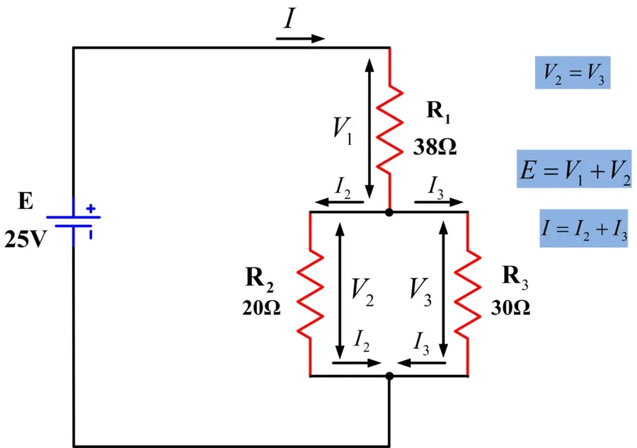
Example 2: Three Resistors in Parallel
Let's extend this to a three-resistor scenario. Consider resistors R1 = 10 Ω, R2 = 20 Ω, and R3 = 30 Ω connected in parallel. Here, we apply the reciprocal formula:
1/Req = 1/R1 + 1/R2 + 1/R3
Substituting the values:
1/Req = 1/10 Ω + 1/20 Ω + 1/30 Ω
1/Req = 6/60 + 3/60 + 2/60
1/Req = 11/60
Req = 60/11
Req ≈ 5.45 Ω
Therefore, the equivalent resistance for these three resistors in parallel is approximately 5.45 Ω. Notice how adding a third resistor further reduces the total equivalent resistance.
Troubleshooting Common Issues with Parallel Resistors
Diagnosing and rectifying problems in parallel resistor circuits requires a systematic approach, often involving the use of a multimeter to measure voltage, current, and resistance. Common issues such as open circuits or incorrect resistor values can significantly alter circuit behavior and must be identified and corrected.
Here are common issues with parallel resistors:
- Open Circuit in a Branch
An open circuit in one branch of a parallel resistor network will prevent current flow through that specific branch. While the overall circuit may still function, the total resistance increases, and the current distribution is altered. It is imperative to verify continuity across each resistor using a multimeter in resistance mode to identify the open circuit. If a resistor is physically broken or there is a disconnection, the voltage measured across that path will be the full source voltage, and the current will be zero. - Incorrect Resistor Value
Using a resistor with an incorrect value will directly affect the equivalent resistance of the circuit and impact the current distribution. A multimeter can be used to measure the actual resistance value of each resistor and verify against its color code or marked value. If the value deviates significantly from the expected range, the resistor should be replaced to achieve the intended circuit characteristics. Check the resistor before installation in the circuit to confirm its value, as you may have the wrong part. - Short Circuit in a Branch
A short circuit in a branch will result in significantly low resistance on that branch, with the majority of the current flowing through it rather than the other branches. This can cause overheating of the shorted element and the power source and could potentially lead to component damage. An inspection for unintended shorts and a resistance check across each branch is necessary to diagnose short circuits.
Using a Multimeter for Troubleshooting: A multimeter is indispensable for diagnosing issues in parallel resistor circuits. Follow these steps:
- Resistance Measurement
With the power off, use the multimeter in resistance mode to check each resistor’s value directly. Compare the measured value with the marked or color-coded value. This can reveal incorrect resistor values or open circuits. - Voltage Measurement
With the circuit powered, measure the voltage drop across each resistor. In a parallel circuit, the voltage drop across all branches should be equal to the supply voltage. Discrepancies may indicate a problem within the circuit. - Current Measurement
Measure the current through each branch using the multimeter in ammeter mode. This requires breaking the circuit to insert the meter in series. The current distribution can be verified against calculated values to diagnose issues.
Frequently Asked Questions About Resistors in Parallel
Understanding parallel resistor circuits often brings up several key questions. This section addresses those common queries, providing concise and clear explanations to solidify your understanding of parallel resistor behavior.
- What is the fundamental rule for resistors in parallel?
The fundamental rule for resistors in parallel is that the voltage across each resistor is the same. This is because all resistors share the same two connection nodes. The current, however, divides among the parallel branches, with the amount of current in each branch inversely proportional to the resistance of that branch. - How do I calculate the total resistance of resistors in parallel?
The total (or equivalent) resistance of resistors in parallel is calculated using the reciprocal of the sum of the reciprocals formula: 1/R_total = 1/R1 + 1/R2 + 1/R3 + ... + 1/Rn where R1, R2, R3... Rn are the values of individual resistors. The total resistance is always less than the smallest individual resistor in the parallel network. To find the total resistance you must take the inverse of the result. - What is the simplified formula for calculating the equivalent resistance of two resistors in parallel?
When only two resistors are in parallel, a simplified formula can be used: R_total = (R1 * R2) / (R1 + R2). This product-over-sum formula avoids the need for calculating reciprocals and is computationally efficient in this specific scenario. - How is the current distributed in a parallel circuit and how do I find the current through each resistor?
In a parallel circuit, the total current from the source divides among the different branches according to each branch's resistance. The current through each resistor (I_n) can be calculated by applying Ohm's Law: I_n = V / R_n, where V is the common voltage across the parallel combination, and R_n is the resistance of that particular resistor. The sum of individual branch currents will equal the total current from the source. - What happens to the overall resistance when adding more resistors in parallel?
Adding more resistors in parallel *decreases* the overall equivalent resistance of the circuit. This is because each additional resistor provides another path for current to flow, effectively reducing the total opposition to current flow. - How does the behavior of resistors in parallel differ from resistors in series?
Resistors in series have the same current flowing through them, with the total resistance increasing by simply adding the individual values. In contrast, resistors in parallel share the same voltage, and the total resistance decreases as more resistors are added. The total current flow behavior is also the opposite; in series the current is the same, in parallel the current divides. - Why would I use parallel resistors instead of a single resistor?
Parallel resistors are often used to achieve specific or non-standard resistance values not readily available as single resistors. Additionally, parallel configurations are used in circuits to distribute power and provide multiple paths for current, making the circuit more reliable as the failure of one resistor doesn't cause the entire circuit to fail.
In conclusion, understanding resistors in parallel is crucial for any aspiring or experienced electronics enthusiast. From using the reciprocal formula to calculate equivalent resistance to comprehending the division of current among parallel branches, the concepts discussed here provide a solid foundation for analyzing and designing complex circuits. By knowing how parallel resistors work, you can effectively manage current and voltage, achieve specific resistance values, and design more robust and efficient electronic systems. Remember, the key is to practice calculations, apply the principles in real-world projects, and continue to explore the fascinating world of electronics with resistors in parallel.