Mastering Resistors: Series vs. Parallel Circuits Explained
Imagine a city's traffic system; sometimes cars line up one after the other (like resistors in series), and sometimes they diverge into multiple paths (like resistors in parallel). Understanding how resistors behave in series and parallel configurations is fundamental to electronics design and circuit analysis. This article will demystify these concepts and show you how to calculate equivalent resistances, empowering you to build and understand various circuits.
What are Series and Parallel Circuits?
Series and parallel circuits represent the two fundamental ways in which electrical components, particularly resistors, can be connected within a circuit, each configuration exhibiting distinct behaviors regarding current and voltage flow. Understanding these differences is crucial for effective circuit design and analysis.
In a **series circuit**, components are connected end-to-end, forming a single path for current to flow. Consequently, the current remains the same throughout the entire circuit, while the total voltage is divided among the resistors. Visually, imagine a chain where each link is a resistor, the current is analogous to the chain moving as one.
Contrastingly, in a **parallel circuit**, components are connected across each other, creating multiple paths for current flow. Here, the voltage is the same across all parallel branches, while the current divides among the resistors. A parallel circuit can be visualized as multiple lanes on a highway, the total current divides up into each lane.
Resistors in Series: The Straight Path
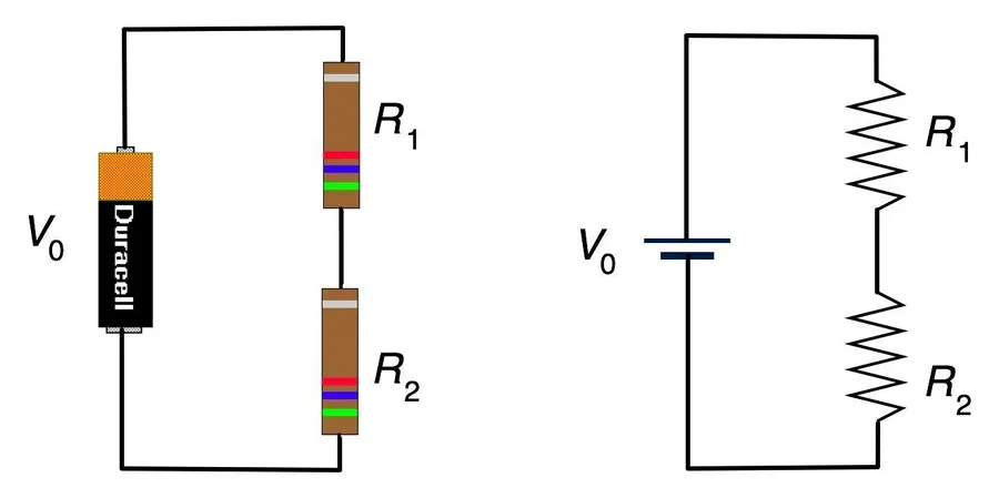
In a series circuit, resistors are connected end-to-end, forming a single path for current to flow. This configuration results in the same current passing through each resistor, while the total voltage is divided across all resistors in the series. Understanding this fundamental principle is critical for analyzing and designing electronic circuits.
Key Characteristics of Series Resistor Circuits:
- Current is Constant
The same amount of current flows through every component in the series circuit. This is because there is only one path for the electrons to move. - Voltage is Divided
The total voltage of the source is split among the resistors. Each resistor experiences a voltage drop proportional to its resistance according to Ohm's Law (V=IR). - Total Resistance
The total resistance (Rt) of resistors in series is the sum of individual resistances: Rt = R1 + R2 + R3 + ... This means that adding more resistors increases the overall resistance of the circuit.
Real-World Example: Simple String Lights
A classic example of a series circuit is a simple string of holiday lights. Each light bulb acts as a resistor. If one bulb burns out (creating an open circuit), the current path is broken, and all the other lights go out because they share the same current path. This illustrates the interdependence of components within a series circuit.
Mathematical Representation:
R_t = R_1 + R_2 + R_3 + \cdots + R_n
Where R_t is the total series resistance and R_1, R_2, R_3 to R_n are the individual resistances of the resistors in the circuit.
Resistors in Parallel: Multiple Paths
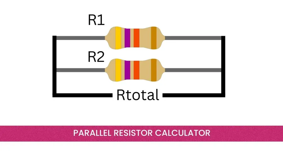
In a parallel circuit, resistors are connected side by side, providing multiple paths for current to flow. This configuration contrasts with series circuits, where there is only a single path for current. A key characteristic of parallel circuits is that the voltage is the same across each resistor, while the total current is divided amongst the branches.
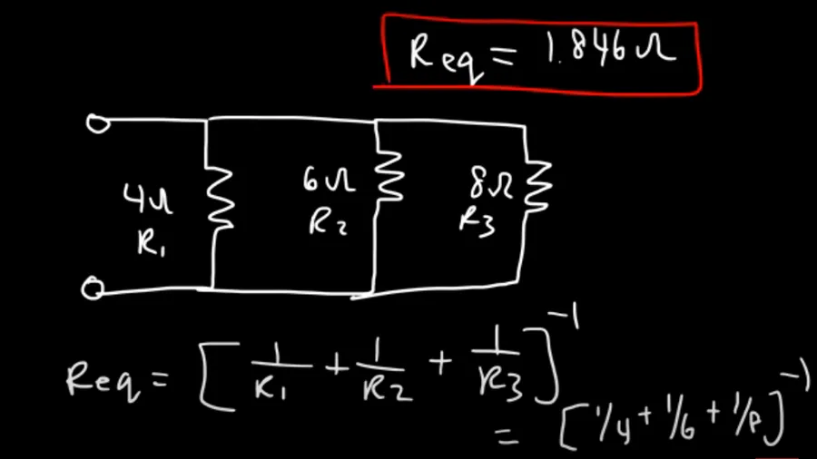
The total resistance of a parallel circuit is always less than the smallest individual resistance, a counterintuitive but crucial property. This is because adding more parallel paths effectively increases the overall ability of the circuit to conduct current. Calculating the total or equivalent resistance requires a reciprocal relationship, with special handling for only two resistors.
The general formula for calculating the total resistance (Rt) of resistors in parallel is given by: 1/Rt = 1/R1 + 1/R2 + 1/R3 + ... , where R1, R2, R3,... are individual resistor values. A simplified equation to calculate the total resistance of two parallel resistors, R1 and R2 is: Rt=R1R2/(R1+R2)
Consider a common application, a multi-bulb lighting fixture. In this case, each bulb acts as a resistor, wired in parallel, if one bulb burns out the remaining bulbs continue to function normally. This is because the voltage remains constant across each bulb, allowing current to flow through other branches, independent of the failed path. The total current is shared between each bulb path, so that current is supplied and the individual bulbs can function normally.
| Characteristic | Description |
|---|---|
| Connection | Resistors connected side by side, providing multiple paths for current. |
| Voltage | Remains constant across each resistor. |
| Current | Total current is divided among the resistors. |
| Total Resistance | Total resistance is always less than the smallest individual resistance. Calculated by 1/Rt = 1/R1 + 1/R2 + 1/R3 + ... or Rt=R1R2/(R1+R2) for two resistors. |
Calculating Equivalent Resistance: Simplifying Circuits
Calculating equivalent resistance is a fundamental technique in circuit analysis, allowing complex networks of resistors to be simplified into a single effective resistance. This simplification is crucial for understanding the overall behavior of a circuit, such as total current flow and voltage distribution, making circuit analysis and design more tractable.
By replacing series or parallel resistor combinations with their equivalent resistance, complex circuits can be reduced to simpler forms. This not only aids in analysis but also provides a practical approach to predict how a circuit will behave under different operating conditions. The equivalent resistance represents the total opposition to current flow that the network of resistors presents to the voltage source.
The process of simplifying complex circuits involves systematically identifying series and parallel resistor configurations. Once identified, the appropriate formulas (Rt = R1 + R2 + ... for series and 1/Rt = 1/R1 + 1/R2 + ... for parallel, or Rt = (R1*R2)/(R1+R2) for two parallel resistors) are applied to derive a single equivalent resistance for each identified network. This process is repeated until the entire network is reduced to a single effective resistor, simplifying subsequent calculations.
Series vs. Parallel: Key Differences Summarized
Understanding the fundamental differences between series and parallel circuits is crucial for circuit analysis and design. These configurations dictate how current, voltage, and resistance behave within a circuit, impacting overall functionality. The table below provides a concise comparison of these key characteristics.
| Characteristic | Series Circuit | Parallel Circuit |
|---|---|---|
| Current | Constant throughout the circuit | Divided among branches |
| Voltage | Divided across each resistor | Constant across each branch |
| Total Resistance | Rt = R1 + R2 + R3 + ... | 1/Rt = 1/R1 + 1/R2 + 1/R3 + ... or Rt=R1R2/(R1+R2) for two resistors |
| Failure Mode | Open circuit if one component fails | Other branches remain functional if one component fails |
Practical Applications of Series and Parallel Resistors
Resistors, when configured in series or parallel arrangements, serve as fundamental building blocks in a wide array of electronic circuits. Their distinct behaviors in each configuration enable engineers to manipulate current and voltage to achieve desired functionalities across various applications.
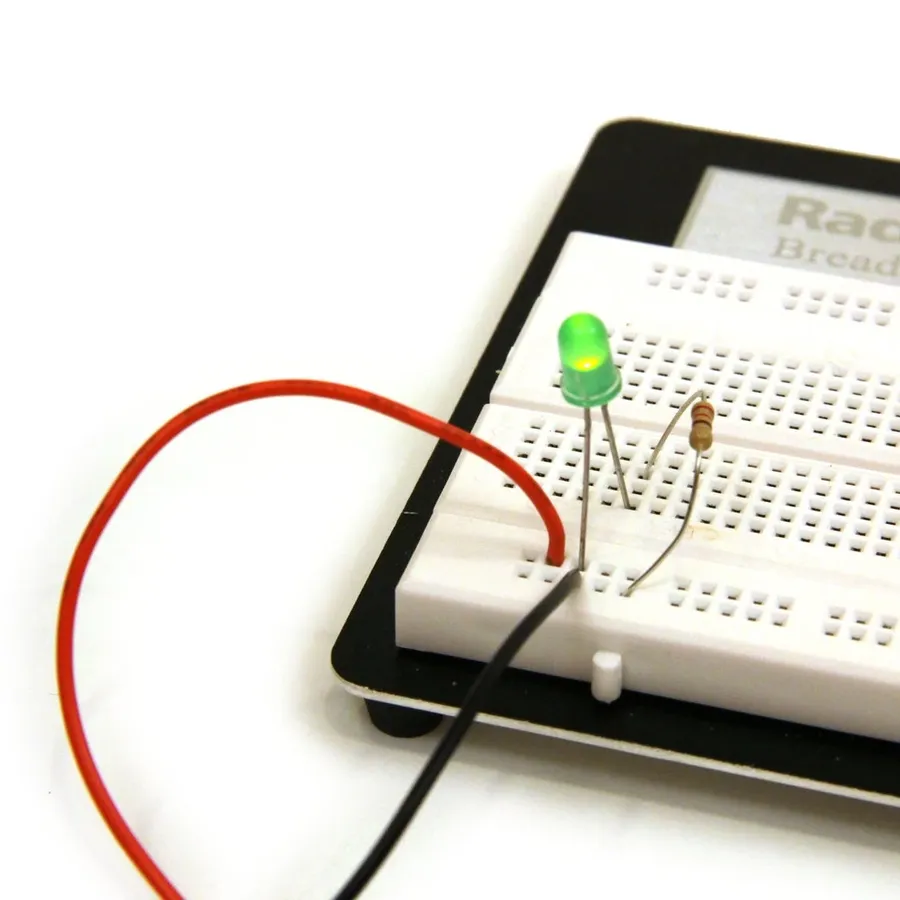
- LED Lighting:
In LED lighting, a resistor is often placed in series with the LED. This resistor limits the current flowing through the LED, preventing it from burning out due to excessive current. This is a simple application of Ohm's Law, where the resistor's value is chosen to drop a certain voltage based on the LED's specifications. - Voltage Dividers:
Series resistors are critical for creating voltage dividers. These circuits reduce a voltage to a specific level, allowing microcontrollers or other electronic components to be used safely. The ratio of the resistor values determines the resulting output voltage. This is foundational in many circuits needing different voltage levels. - Sensor Circuits:
Many sensors output a small change in resistance as a response to physical stimuli. Resistors in parallel or series are utilized to convert this change in resistance to a measurable voltage signal or current. Wheatstone bridges are good examples using combination of series and parallel resistors in sensitive measurements. - Current Limiting:
Resistors are crucial for limiting current in circuits to protect sensitive components. By carefully selecting a resistor value, one can limit current in a given branch. Series resistors are employed to achieve this, which is crucial in many electronic devices to ensure they function safely and reliably. - Pull-Up and Pull-Down Resistors:
These resistors are used to set a default state for an input pin when it's not actively driven by another component. Pull-up resistors connect a pin to the power supply, while pull-down resistors connect a pin to ground. This ensures that a microcontroller or circuit has a stable logic state.
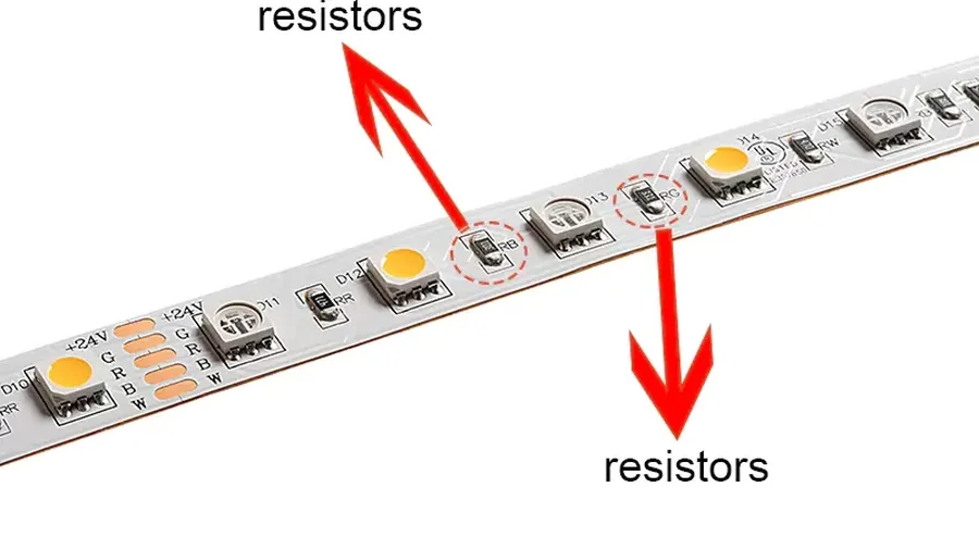
The combination of series and parallel configurations can be strategically used within the same circuits to achieve more complex objectives. For example, a parallel array of LEDs can be used to increase light output and a series resistor can be added to limit the current.
Frequently Asked Questions About Resistors in Series and Parallel Circuits
Understanding the behavior of resistors in series and parallel circuits is fundamental in electronics. This section addresses common questions to solidify your grasp of these concepts, providing clear, concise answers.
- What are the formulas for calculating total resistance in series and parallel circuits?
In a series circuit, the total resistance (Rt) is the sum of all individual resistances: Rt = R1 + R2 + R3 + .... In a parallel circuit, the reciprocal of the total resistance is the sum of the reciprocals of the individual resistances: 1/Rt = 1/R1 + 1/R2 + 1/R3 + .... For two resistors in parallel, a simplified formula is often used: Rt = (R1 * R2) / (R1 + R2). - What are the rules regarding current and voltage in series and parallel resistor configurations?
In a series circuit, the current is the same through all resistors, while the voltage is divided across each resistor. The sum of the voltage drops across each resistor equals the total voltage applied to the series circuit. In a parallel circuit, the voltage is the same across all resistors, while the current is divided among the parallel branches. The sum of the currents in each branch equals the total current entering the parallel circuit. - What is the key difference between resistors connected in series and in parallel?
The fundamental difference lies in how the resistors are connected within the circuit. In a series circuit, resistors are connected end-to-end, forming a single path for current. In a parallel circuit, resistors are connected side-by-side, creating multiple paths for current to flow. This difference impacts how current and voltage are distributed. - How can I identify if resistors are connected in series or parallel?
Visually, series resistors are connected one after the other along a single path. Parallel resistors, on the other hand, provide multiple paths for current flow, appearing as branches from a common point. If a single break in the circuit would stop current flow through all the resistors, they are in series; if the current flow is not disrupted to each other, they are in parallel. In a circuit diagram, you can trace the current flow to determine if there is one path or multiple paths. - How does adding more resistors affect the total resistance in a series circuit?
Adding more resistors in series always increases the total resistance of the circuit. This is because each additional resistor adds to the overall opposition to current flow, impeding current. - How does adding more resistors affect the total resistance in a parallel circuit?
Adding more resistors in parallel decreases the total resistance of the circuit. Each additional path provides an alternative route for current to flow, which, by Ohm's law, means total resistance decreases. - In a parallel circuit, if one resistor fails (becomes an open circuit), what happens to other resistors?
If a single resistor in a parallel circuit fails, meaning it opens and prevents current flow, current will cease flowing through that specific branch. However, the other parallel branches, and their associated resistors, will continue to function as normal, as the remaining circuit paths still provide complete circuits from the voltage source.
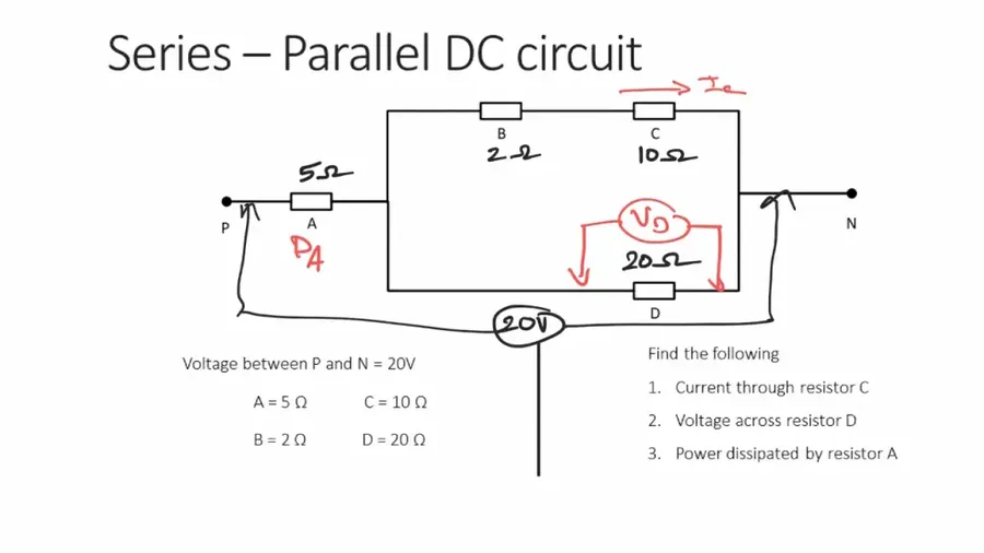
Advanced Concepts: Combining Series and Parallel Resistors
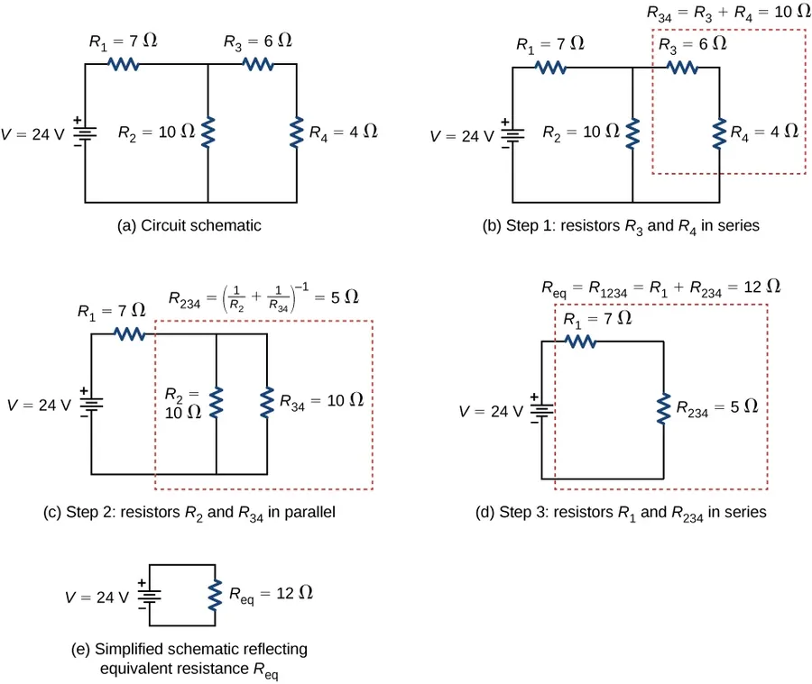
Real-world circuits often feature a combination of both series and parallel resistor configurations, requiring a systematic approach to analyze and simplify them. This section explores how to dissect complex circuits into manageable parts, using equivalent resistance calculations to determine the overall behavior of the network.
The key principle in analyzing these mixed circuits is to work progressively, identifying and simplifying either series or parallel segments before combining the results. This step-by-step process significantly reduces the complexity, allowing for straightforward calculation of the circuit's total resistance and, subsequently, current and voltage distribution.
- Identify Series and Parallel Sections
Begin by visually inspecting the circuit diagram to locate areas where resistors are connected purely in series or parallel. These sections can be treated as individual units for initial simplification. - Calculate Equivalent Resistance for Each Section
Apply the appropriate series or parallel resistance formulas to find the equivalent resistance for each identified section. This effectively replaces a group of resistors with a single resistor that has the same impact on the circuit's overall behavior. - Redraw Simplified Circuit
After calculating an equivalent resistor, redraw the circuit diagram using this simplified components. This step simplifies the circuit visually, aiding in identifying the next stage of simplification. Repeat this process by identifying next series or parallel configuration. - Repeat the simplification process
Continue identifying and simplifying series and parallel sections until the entire network is reduced to a single equivalent resistance. Once reduced to a single equivalent resistance, the overall properties of the complex combination of series and parallel resistors are simplified. - Calculate Circuit Variables
Once the total equivalent resistance (Rt) is found, use Ohm's Law (V=IR) to determine the total current, voltage drops, and current distribution at different segments of the circuit. This provides complete understanding of the entire network.
Consider a circuit where a series combination of a 10-ohm resistor and a 20-ohm resistor is placed in parallel with a 30-ohm resistor. First, the 10-ohm and 20-ohm resistors in series are combined to create a 30-ohm equivalent resistance. Next, this 30-ohm equivalent resistor is in parallel with the 30-ohm parallel resistor. Finally, calculate the equivalent resistance of two 30-ohm resistors in parallel as 15-ohms.
Troubleshooting: Identifying Resistors in Series and Parallel
Identifying whether resistors are connected in series or parallel is a crucial skill for circuit analysis and troubleshooting. This section provides practical methods, encompassing both visual inspection and measurement techniques, to accurately determine resistor configurations within a circuit.
- Visual Inspection Techniques:
Visually tracing the connections in a circuit diagram or on a physical circuit board is often the first step. Series resistors will appear connected end-to-end, forming a single path, while parallel resistors will have their terminals connected to the same two nodes, creating multiple paths. Pay close attention to the layout and confirm if the current flow would be divided or unified when tracing connections. - Using a Multimeter for Resistance Measurement:
With power off, measure the resistance between two points in a circuit. If the resistance between two points is equal to the sum of individual resistors between them, they are likely in series. If the inverse of the total resistance is equal to the sum of the inverses of individual resistors, they are in parallel. - Using a Multimeter for Voltage Measurement:
When the circuit is powered, if the voltage across two or more resistors is identical, they are in parallel. If the voltage drops across two or more resistors add up to the total voltage source applied between them, then they are in series. - Understanding Circuit Diagrams:
Circuit diagrams typically represent resistors in series as a linear sequence and parallel resistors as branches off a central node. Confirm this representation aligns with physical connectivity of components. - Physical Component Arrangement on Circuit Boards:
On a circuit board, series resistors are likely to be in a direct line, while parallel resistors will share the same connection points. Trace the conductive paths on the board itself for clarity.
Understanding the behavior of resistors in series and parallel is vital for anyone working with electrical circuits. Like carefully managing a network of roads to ensure efficient traffic flow, these concepts allow us to design, control, and troubleshoot electronic devices. By mastering how to calculate total resistances and the differences in current and voltage distributions, you are equipped to tackle a wide range of circuit analysis challenges. Whether it's a simple string of Christmas lights (series) or the complex network of your home's wiring (parallel and combinations thereof), the fundamental principles remain the same. Continuously applying this knowledge is the key to designing innovative and practical electronic solutions.