Mastering the Trim Potentiometer: Precision Control in Your Circuits
In our increasingly tech-driven world, the ability to fine-tune electronic circuits is crucial. Enter the trim potentiometer, or trimpot, a small but mighty component that allows for precise adjustments of resistance. Think of it as the subtle hand that fine-tunes the instruments of our technological orchestra, ensuring each note is just right. This article will demystify the trim potentiometer, exploring its various types, applications, and how you can leverage it for your electronic endeavors.
Understanding the Trim Potentiometer: What is a Trimpot?
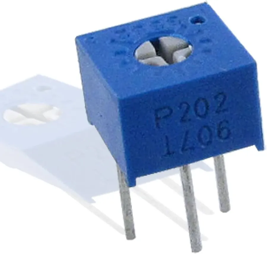
A trim potentiometer, commonly known as a trimpot, is a compact, adjustable resistor primarily used for fine-tuning and calibration within electronic circuits. Unlike standard potentiometers designed for frequent user interaction, trimpots are intended for infrequent adjustments, often during initial setup or maintenance, to achieve precise resistance values.
These small components allow engineers and technicians to accurately set a specific resistance within a circuit, optimizing its performance. Their diminutive size and typically less robust construction make them suitable for internal adjustments where space and durability requirements differ from those of user-facing controls. The primary focus of a trimpot is on achieving precise and stable circuit parameters, not on providing variable control by the end-user.
Key Differences: Trim Potentiometer vs. Standard Potentiometer
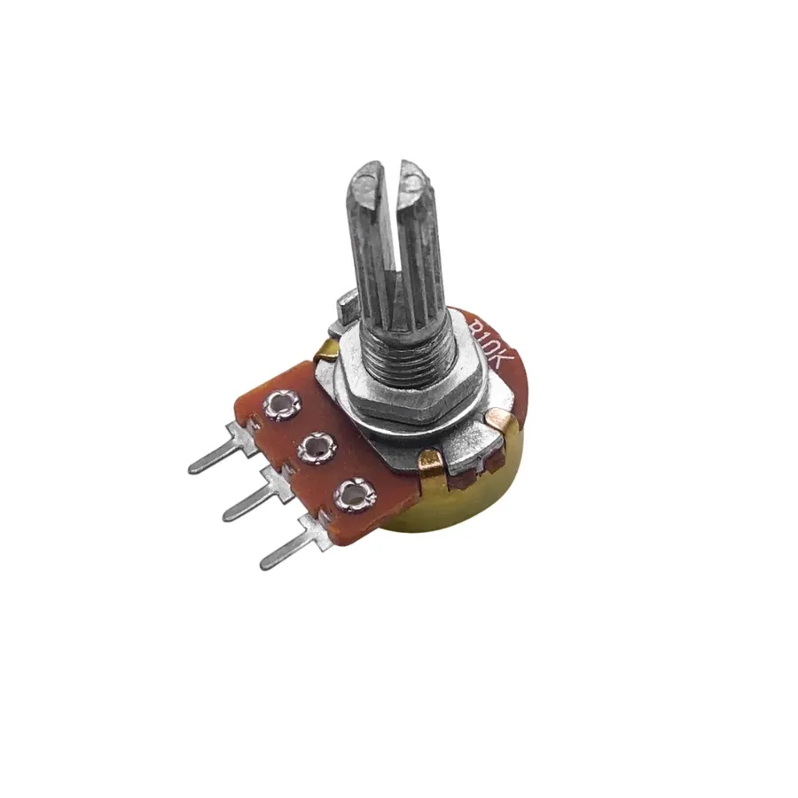
While both trim potentiometers (trimpots) and standard potentiometers are variable resistors that allow for the adjustment of electrical resistance, they serve distinct purposes and are engineered with notable differences in size, adjustment mechanisms, and intended frequency of use. Trimpots are designed for infrequent, precision adjustments, whereas standard potentiometers are built for more regular user interaction.
| Feature | Trim Potentiometer | Standard Potentiometer |
|---|---|---|
| Size | Miniature, compact design | Larger, more substantial |
| Adjustment Mechanism | Small screw or slot requiring a tool | Rotary knob or slider for manual adjustment |
| Accessibility | Typically mounted on a PCB, less accessible | Intended for user-accessible panel mounting |
| Intended Use | Infrequent, precision calibration | Frequent, user-controlled adjustments |
| Durability | Designed for stability and longevity of the setpoint | Designed for repeated adjustment cycles |
| Cost | Lower cost per unit. | Higher cost per unit. |
Types of Trim Potentiometers: Construction and Materials
Trim potentiometers, or trimpots, are constructed using a variety of materials, each offering unique performance characteristics. The choice of material significantly impacts a trimpot's stability, temperature sensitivity, and overall reliability. Understanding these differences is crucial for selecting the appropriate trimpot for a given application.
| Material | Construction | Advantages | Disadvantages | Typical Applications |
|---|---|---|---|---|
| Cermet | A combination of ceramic and metal particles bonded to a substrate. | High stability, low temperature coefficient, good resistance to wear, wide resistance range. | More expensive than carbon, can be more brittle than other materials. | High-precision circuits, industrial equipment, medical devices, applications requiring stable resistance values over temperature. |
| Carbon | Carbon film deposited on a substrate. | Low cost, commonly available. | Less stable, higher temperature coefficient, prone to wear, can exhibit noise due to material degradation. | General-purpose applications, audio equipment, applications with less stringent precision requirements. |
| Wirewound | Fine resistance wire wound around an insulating core. | High power handling, excellent stability, low temperature coefficient. | Higher cost, limited resistance range, can have higher inductance, not suitable for high-frequency applications. | High current and voltage circuits, power supplies, applications requiring accurate, stable resistance values at high power. |
The resistive element's construction and material determine how precisely and reliably the trimpot can adjust and maintain the intended resistance. Selecting a trimpot requires careful consideration of environmental factors and performance requirements, like the need for high precision or high power, to make the right decision.
Mounting Styles: Through-Hole, Surface Mount, and Panel Mount Trimmers

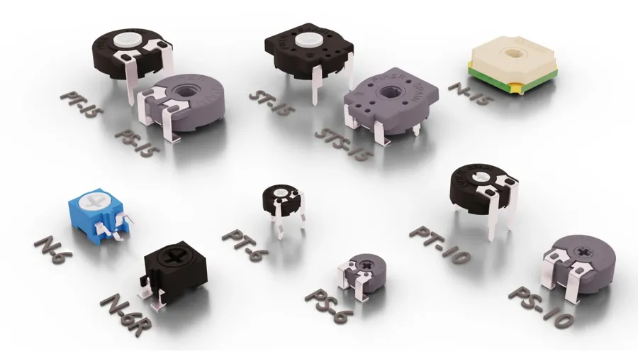
Trim potentiometers are available in various mounting styles, each designed to suit specific application needs and manufacturing processes. The mounting style significantly impacts how the trimpot integrates into a circuit and how it can be accessed for adjustments. The three primary mounting styles are through-hole, surface mount, and panel mount.
| Mounting Style | Description | Advantages | Disadvantages | Typical Applications |
|---|---|---|---|---|
| Through-Hole (TH) | Components are mounted by inserting leads through holes on the PCB and soldered on the opposite side. | Robust mechanical connection, easy for prototyping and manual assembly, good for high-power applications. | Requires more PCB space, not suitable for high-density designs, limited to one side of the board. | Prototyping, low-volume production, manual assembly, higher-power applications |
| Surface Mount (SMT) | Components are soldered directly onto the surface of the PCB without leads passing through holes. | Compact size, suitable for high-density designs, automated assembly, lower manufacturing cost. | More difficult for manual assembly and prototyping, requires specialized equipment, can be less robust for mechanical stress. | High-volume production, compact designs, automated assembly processes |
| Panel Mount | Components are mounted to a panel or chassis, with the adjustment mechanism accessible from the front. | Easy to access and adjust after installation, robust mechanical connection, suitable for frequent adjustments (although trimpots are not designed for such). | Requires extra panel space and mechanical mounting hardware, not space-efficient for PCB. | Equipment where front-panel adjustments are required, calibration of devices |
Trim Potentiometer Applications: Where are They Used?
Trim potentiometers, or trimpots, are indispensable components in electronic circuits requiring precise, infrequent adjustments. Their small size and capacity for fine-tuning make them ideal for a range of applications, from calibration to control, across various sectors.
- Sensor Calibration Circuits
Trimpots are critical for calibrating sensors, including those for temperature, pressure, and light. They allow engineers to compensate for manufacturing tolerances and environmental variations, ensuring accurate and reliable sensor readings. For instance, in a temperature sensor circuit, a trimpot can be adjusted to fine-tune the output voltage to match a known temperature standard. - Audio Equipment Fine Tuning
In audio circuits, trimpots are used for precise adjustments of gain, bias, and offset levels. They allow for subtle corrections during the manufacturing process, optimizing sound quality in amplifiers, mixers, and equalizers. These adjustments ensure that all channels operate uniformly and reduce unwanted distortion. - Motor Speed Control
Trimpots play a key role in motor control circuits, enabling precise speed adjustments. By modifying the voltage or current supplied to a motor, a trimpot can optimize its performance and synchronize it with other system components. This application is particularly beneficial in systems that require precise control over movement. - Power Supply Voltage Regulation
Trimpots are essential in voltage regulators, facilitating the fine-tuning of output voltages to specified tolerances. This allows power supplies to deliver precise and stable voltages that are critical for sensitive electronic equipment. These adjustments ensure that components receive the exact voltage required for optimal performance and longevity. - Robotics and Automation
In robotics and automation, trimpots are used for precise adjustments of servo motors, position sensors, and other feedback control systems. They allow for fine-tuning of robotic arms, ensuring accurate and repeatable movements. These adjustments are critical for the consistent and reliable operation of these complex systems. - Test and Measurement Equipment
Trimpots are extensively used in test and measurement equipment for calibration and compensation. They enable accurate adjustment of reference voltages, current levels, and other parameters, which is essential for precise measurement readings. This application ensures that the equipment provides reliable and accurate results when testing and validating other circuits.
Selecting the Right Trim Potentiometer: Key Specifications
Selecting the appropriate trim potentiometer hinges on understanding its key specifications, ensuring it meets the precise demands of your application. These parameters dictate performance, stability, and the overall effectiveness of the component within a circuit.
| Specification | Description | Importance |
|---|---|---|
| Resistance Value | The total resistance between the two end terminals of the potentiometer, often expressed in ohms (Ω). | Critical for setting the operating range of the circuit; must match design requirements. |
| Tolerance | The permissible variation in the actual resistance value from the stated nominal resistance, given as a percentage. | Impacts the precision of the adjustment and must be considered for sensitive applications. |
| Power Rating | The maximum power the potentiometer can dissipate without damage, measured in watts (W). | Essential to prevent overheating and component failure; must exceed expected power dissipation. |
| Temperature Coefficient | The change in resistance per degree Celsius (°C), influencing stability at different operating temperatures. | Important for circuits operating in variable temperature environments to ensure consistent performance. |
| Adjustability | The mechanical mechanism for adjusting the resistance, including single-turn, multi-turn, and through-hole/SMT. | Determines the precision and ease of adjustment and the physical installation method. |
| End Resistance | The resistance between the wiper and the terminal at either end of the adjustment, measured in ohms (Ω). | Important for extremely low resistance adjustments; should be minimized for the best precision. |
| Wiper Travel | The distance the wiper travels between the two ends of the resistive element, measured in degrees or revolutions. | Influences the precision of the resistance adjustment. Multi-turn trimpots usually offer finer adjustments. |
Frequently Asked Questions About Trim Potentiometers
This section addresses common queries regarding trim potentiometers, offering clarity on their usage, adjustment, and identification. It aims to resolve user uncertainties and provide accurate information based on first principles.
- What exactly is a trimming potentiometer, or trimpot?
A trimming potentiometer, often called a trimpot, is a miniature adjustable resistor designed for infrequent, fine-tuning adjustments within a circuit. Unlike standard potentiometers, which are frequently adjusted by users, trimpots are typically set during the manufacturing or calibration process and then left untouched. They are crucial for precisely calibrating circuit parameters. - What is the primary difference between a trim potentiometer and a standard potentiometer?
The key differences lie in their size, accessibility, and typical use. Trim potentiometers are smaller, less accessible (often requiring a tool for adjustment), and intended for infrequent adjustments, mainly during calibration. Standard potentiometers are larger, designed for frequent user adjustments, and typically have a knob or slider for easy access. Both control resistance, but their application contexts differ greatly. - Are trimpots and potentiometers the same?
While both trimpots and potentiometers are variable resistors, they serve different purposes. A potentiometer is generally used as a user-adjustable control, such as a volume knob, whereas a trimpot is intended for precision calibration and is not designed for frequent adjustments. Thus, while they share the function of resistance adjustment, their practical applications are distinct. - How do I interpret the markings on a trimmer potentiometer?
Markings on a trimmer potentiometer typically indicate its resistance value (e.g., 103 for 10k ohms), a manufacturer code, and sometimes a date code. The resistance value is typically encoded as a three- or four-digit number, where the first two or three digits represent the significant figures, and the last digit represents the multiplier (10^x). For example, 103 signifies 10 * 10^3 = 10,000 ohms or 10kΩ. Refer to the datasheet of the specific part for full details and decoding. - How should I turn or adjust a trimmer potentiometer?
Trimmer potentiometers are typically adjusted using a small screwdriver or a specialized adjustment tool to precisely rotate their adjustment screw or slider. It is critical to make very small, incremental adjustments. Avoid over-torqueing or forcing the adjustment mechanism, as this can damage the trimpot. Use a multimeter to monitor the change in resistance or voltage while adjusting. - What tools are recommended to adjust a trim potentiometer?
The most suitable tool is a small, insulated screwdriver or a specialized trim potentiometer adjustment tool, often made of plastic or ceramic to prevent short circuits. The tip of the tool should fit the adjustment mechanism of the specific trimpot, whether that is a screw, a slot, or a slider. Using the wrong tool can damage the trimpot and cause instability or failure. - When should a trim potentiometer be replaced?
A trim potentiometer should be replaced if it is exhibiting signs of damage, such as a cracked body, a broken adjustment mechanism, or inconsistent readings in resistance. Also, if a trimpot has reached the end of its lifespan (determined by the manufacturer's specifications), or is no longer providing the required stability or tolerance, it must be replaced. It is advisable to keep a record of the devices calibration dates to pre-empt issues in aging.
Practical Guide: Adjusting a Trim Potentiometer Safely and Effectively
Adjusting a trim potentiometer requires precision and care to avoid damaging the component or the circuit. Unlike standard potentiometers designed for frequent adjustments, trimpots are intended for infrequent calibration. This section outlines the proper techniques, tools, and safety precautions for effective and safe adjustment.
- Essential Tools for Trimpot Adjustment
Use the right tools. A small flat-head screwdriver, preferably a precision screwdriver set, is crucial. Avoid using excessively large tools that can damage the trimpot or surrounding components. Ceramic or plastic adjustment tools are recommended for delicate adjustments in high-sensitivity circuits to avoid accidental short circuits. - Step-by-Step Adjustment Procedure
Begin by identifying the trimpot's adjustment mechanism. Typically, this is a slot or a small screw. Before adjustment, note the starting position as a reference. Make small, incremental turns, and observe the circuit’s behavior. Avoid forceful adjustments, as they can cause permanent damage. If the desired resistance is not reached, check the circuit and the potentiometer's specifications before further adjustment. Recheck circuit parameters following trimpot adjustment to ensure the device is operating within its intended range. - Safety Precautions During Adjustment
Always power down the circuit before making any adjustments, unless the adjustment is specifically designed to be done under power and this is noted in the components specifications. Ensure the power supply is stable, and that the circuit is not subjected to voltage or current extremes during adjustments. Wear appropriate personal protective equipment (PPE) such as ESD-safe gloves to prevent electrical hazards and static damage.
| Adjustment Consideration | Description |
|---|---|
| Tool Selection | Choose a small, flat-head screwdriver or dedicated adjustment tool. |
| Incremental Turns | Make small adjustments, observe the results, and proceed cautiously. |
| Power Consideration | Adjust after the circuit is powered down, unless otherwise specified. Ensure a stable and correct power supply. |
| Component Protection | Avoid applying excessive force and causing damage, especially to sensitive circuit boards and other components. |
| Static Protection | Use ESD-safe tools and wear grounding to protect from ESD damage |
Troubleshooting: Common Problems and Solutions with Trim Potentiometers
Trim potentiometers, while robust, can exhibit problems that affect circuit performance. These issues generally manifest as erratic resistance readings, intermittent connections, or complete failure. Understanding common failure modes and employing systematic troubleshooting techniques are key to maintaining circuit integrity. This section addresses these common issues, offering practical solutions and preventive measures.
- Noisy or Erratic Resistance Readings
This is often caused by a worn or dirty wiper contact. Dust, oxidation, or mechanical wear can disrupt the smooth movement of the wiper across the resistive track. A temporary fix might involve gently rotating the trimmer through its full range to scrape off surface contaminants. However, the only lasting solution is usually replacement. - Intermittent Connections
Intermittent connections often result from poor solder joints, cracked PCB traces near the trimmer, or loose internal connections within the trimmer itself. Careful visual inspection and reflowing solder connections can rectify these issues. If the internal connections are the problem, then the unit should be replaced, repair will often not produce a lasting repair. - Damaged or Broken Trimpot
Physical damage to the trimmer, such as a broken adjustment screw or cracked housing, makes it unreliable and unusable. Improper adjustment techniques such as using excessive force, or the wrong adjustment tool may cause these issues. Replacement is the only remedy in these cases. - Out-of-Tolerance Resistance
Over time or due to excessive temperature exposure, the resistance of a trimmer can drift outside of its specified tolerance range. A simple check against the expected resistance is the first step, when the trimpot is found to be outside of tolerance, then replacement is the only solution. - Incorrect Adjustment
Incorrect or over adjustment, can result in an unstable or unreliable trimpot. Careful and proper adjustment of the trimpot will be needed to ensure that the circuit will function correctly. If the trimpot is over adjusted, replacement may be needed.
| Symptom | Possible Cause | Solution |
|---|---|---|
| Noisy Resistance | Worn wiper/contamination | Replacement, Clean with caution |
| Intermittent Connections | Poor solder joints/internal issue | Reflow solder/Replacement |
| Physically Broken | Excessive force or mishandling | Replacement |
| Out of Tolerance | Aging/overheating | Replacement |
| Incorrect Adjustment | Improper adjustment or over adjustment | Careful adjustment/Replacement |
Preventive measures include selecting trimpots with adequate power ratings and temperature coefficients for their application, protecting components from excessive mechanical stress, and utilizing proper adjustment techniques. When replacing a trimpot, it's essential to choose a component with equivalent specifications to ensure proper circuit function. If a through-hole version is replaced with a surface-mount version, or vice versa, adapters may need to be used to ensure that the replacement component is compatible. Always ensure that the unit has been removed from the circuit before working on it to avoid causing further damage to the trimpot, or the circuit.
Advanced Trim Potentiometer Usage: Calibration Techniques & Best Practices
Achieving optimal performance from a trim potentiometer often requires more than just a simple adjustment. Advanced calibration techniques and best practices are crucial for maximizing accuracy and ensuring long-term stability in circuits using trimpots. This section delves into specific strategies for precise circuit adjustments.
- Iterative Adjustment with Measurement Feedback
For high-precision calibration, implement an iterative approach. Start with a coarse adjustment, measure the output using appropriate instrumentation, and then fine-tune the trimpot based on the measurement results. Repeat this process until the desired parameter is achieved. This approach compensates for any non-linearity in the adjustment mechanism. - Use of Specialized Calibration Tools
Employ specialized tools, such as digital multimeters with high accuracy and precision, oscilloscope for dynamic signal calibration, and dedicated trimmer adjustment tools, to ensure precise and repeatable adjustments. The use of a non-conductive trimming tool (such as a plastic screwdriver) can prevent accidental short circuits and damage to the trimmer. - Temperature Considerations
Be mindful of the effects of temperature on the trim pot's resistance and the surrounding circuitry. Perform calibration at the expected operating temperature of the system. If the operating environment experiences significant temperature fluctuations, consider implementing temperature compensation circuits or using trimpots with low temperature coefficients. - Minimizing Mechanical Stress
Avoid over-torquing the trimmer adjustment screw. The force should be applied gradually to avoid damage to the trimmer mechanism. Consider the mounting of the trim pot to ensure it is not subjected to mechanical stress that could affect its long-term performance. This reduces mechanical backlash and drift. - Circuit Stabilization
Allow sufficient time for the circuit to stabilize after each adjustment. This time will depend on the circuit and components used but is usually between a few seconds up to a few minutes, particularly for circuits with capacitors or thermal time constants. This ensures that your measurement is accurate. - Document Settings and Calibration Procedures
Always record the final trimmer settings (e.g., resistance or measurement values) and calibration procedures. This is essential for traceability in a production setting, for future adjustments or re-calibration, and for troubleshooting. It also allows for standardization across multiple devices or circuit boards - Preventive Measures
Consider applying a sealant or locking compound to the trimpot after final adjustment to prevent accidental changes due to vibration or tampering, particularly in applications where mechanical shock may be present. This will also protect the trimmer from environmental contamination.
The trim potentiometer, though small, is a critical component in ensuring the accuracy and reliability of electronic circuits. From fine-tuning audio equipment to calibrating precision instruments, its ability to make precise resistance adjustments is invaluable. By understanding the different types, applications, and adjustment techniques, you can harness the power of the trimpot to achieve optimal performance in your projects, pushing the boundaries of what’s possible in electronics. As technology evolves, the need for accurate and reliable circuit adjustments will only increase, making the trim potentiometer a crucial tool for engineers and enthusiasts alike.