SS34 Schottky Diode: A Comprehensive Guide to Performance and Applications
In the world of electronics, the SS34 diode plays a critical role in power conversion, offering efficiency and reliability in various applications. This tiny workhorse, a type of Schottky diode, is designed to minimize power loss and maximize performance in circuits ranging from everyday gadgets to sophisticated industrial equipment. Let's dive into the world of the SS34 diode, exploring its core characteristics and why it's such a valuable component.
Understanding the SS34 Schottky Diode
The SS34 is a Schottky diode, characterized by its metal-semiconductor junction which creates a low forward voltage drop and very fast switching speed, unlike traditional PN junction diodes. This makes it particularly well-suited for high-frequency applications where efficiency and speed are critical.
At its core, the SS34 uses a Schottky barrier formed by the contact of a metal with a semiconductor. This differs from the P-N junction found in standard diodes. The barrier allows for a low forward voltage drop (typically around 0.5V) and the ability to switch at very high frequencies, enhancing its efficiency in power conversion. The fundamental difference lies in the mechanism of current flow which, in a Schottky diode, is primarily due to majority carriers, leading to faster switching capabilities and lower forward voltage drop.
Key Specifications of the SS34 Diode
The SS34 Schottky diode is characterized by several key specifications that dictate its performance in electronic circuits. These parameters include forward voltage drop, reverse current, maximum current rating, maximum reverse voltage, and temperature ratings. Understanding these specifications is crucial for selecting the appropriate diode for a given application.
| Parameter | Typical Value | Unit | Description |
|---|---|---|---|
| Forward Voltage Drop (Vf) | 0.5 | V | Voltage drop across the diode when conducting in the forward direction. Varies with current and temperature. Refer to datasheet for precise figures at different conditions. |
| Reverse Current (Ir) | 500 | µA | Current flowing through the diode in the reverse direction when reverse voltage is applied. Usually very small but increases with temperature. Refer to datasheet for precise figures at different conditions. |
| Maximum Forward Current (If) | 3 | A | The maximum continuous current the diode can safely handle in the forward direction without damage. It is important not to exceed this limit to prevent permanent device failure. |
| Maximum Reverse Voltage (Vr) | 40 | V | The maximum voltage that can be applied in the reverse direction before the diode breaks down. Exceeding this voltage can cause irreversible damage to the device. |
| Operating Temperature Range | -55 to +125 | °C | The range of ambient temperatures within which the diode is designed to operate reliably. Exceeding these limits can affect performance and may damage the device. |
Temperature ratings are particularly critical as they affect many other parameters. For instance, forward voltage drop (Vf) typically decreases with increasing temperature, while reverse leakage current (Ir) increases. These temperature-dependent variations must be taken into account when designing circuits for stable and reliable operation, especially in challenging thermal environments.
SS34 Diode Pinout and Package Information
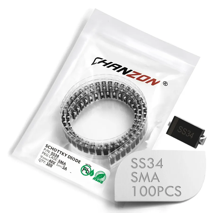
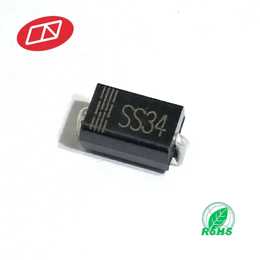
The SS34 Schottky diode is typically housed in a DO-214AC (SMA) surface-mount package. Understanding its pinout and package characteristics is crucial for correct circuit implementation and thermal management.
| Pin | Description |
|---|---|
| Pin 1 | Cathode (typically indicated by a band or marking on the package) |
| Pin 2 | Anode |
The surface mount design of the DO-214AC package presents both advantages and challenges. Its compact size allows for high-density board layouts, but this also means that heat dissipation becomes a critical factor in ensuring reliable operation. Proper thermal management strategies, such as using thermal vias and heat sinks, are often necessary.
Common Applications of the SS34 Schottky Diode
The SS34 Schottky diode is integral to a variety of power electronics applications, primarily due to its low forward voltage drop and rapid switching capabilities. Its efficient operation makes it suitable for applications where energy conservation and high-frequency performance are crucial.
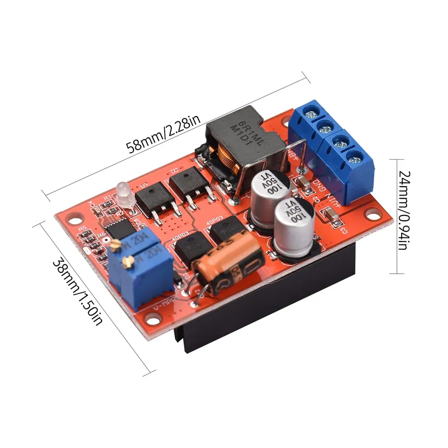
- DC-DC Converters
In DC-DC converters, the SS34 acts as a rectifier, efficiently converting one DC voltage level to another. Its low forward voltage drop minimizes power loss, improving overall converter efficiency and reducing heat generation. This is particularly important in portable devices where battery life is critical. - Freewheeling Diode
The SS34 serves as a freewheeling diode in inductive circuits, such as motor drivers and switching power supplies. When the switching element turns off, the SS34 provides a path for the current to flow, preventing voltage spikes and protecting other components. Its rapid switching capability makes it ideal for high-speed switching applications. - Polarity Protection
In polarity protection circuits, the SS34 diode ensures that the circuit only operates when the correct polarity is applied. It effectively blocks reverse current flow when the power supply is connected incorrectly. The SS34 is particularly suitable due to its low forward voltage drop, which minimizes the voltage loss across the diode when the polarity is correct. - Solar Power Systems
Due to its low forward voltage drop and efficient performance, the SS34 is used in solar power systems. It helps minimize power losses in the system which lead to higher energy conversion efficiency, which is vital for solar applications.
SS34 Diode Equivalents and Replacements
When the SS34 Schottky diode is unavailable or unsuitable for a particular application, identifying appropriate equivalents or replacements is crucial. This section details suitable alternatives, emphasizing the importance of matching key electrical characteristics for seamless integration and optimal circuit performance.
The primary consideration when selecting an SS34 replacement is to match or exceed the following critical parameters:
- Forward Voltage Drop (Vf)
The forward voltage drop should be similar to the SS34, typically around 0.5V at the rated current. Significant deviations may affect circuit performance. - Reverse Current (Ir)
The reverse leakage current should ideally be as low as or lower than the SS34, usually in the microampere range. Higher leakage can increase power consumption. - Maximum Current Rating (If)
The replacement diode must match or exceed the SS34's rated current, which is typically 3A. Ensure the diode’s thermal capacity meets the demands of your application. - Maximum Reverse Voltage (Vr)
The maximum reverse voltage rating should be equal to or greater than the SS34's (typically 40V). Select a diode that provides sufficient margin for the given application to prevent failure under reverse bias conditions. - Operating Temperature Range
Ensure the replacement diode can operate within the application's operating temperature range. This is critical for reliability.
Common alternatives to the SS34 include other Schottky diodes with similar specifications, often differentiated by their specific package styles or manufacturer. Some potential replacement options, include:
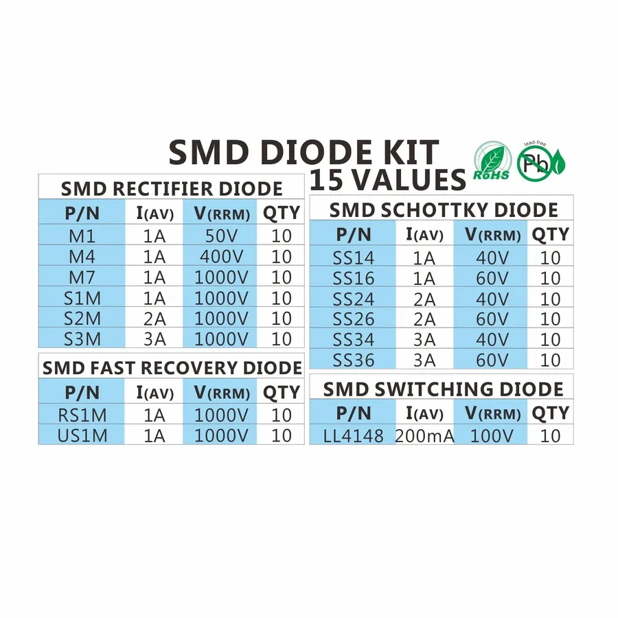
- SS36
A close alternative, often with a higher current rating, and thus might be used where a higher current handling capacity is needed and the package footprint is compatible. - MBR340
Another Schottky diode that may be suitable, it should be reviewed closely based on the manufacturer specifications and performance criteria, such as reverse leakage current, and temperature specifications. - Various Series from Different Manufacturers
Manufacturers like Vishay, ON Semiconductor, and Diodes Incorporated offer Schottky diodes in the same package and with comparable specifications. Always consult the datasheet for verification of suitability.
When selecting a replacement, it is imperative to review the manufacturer's datasheet. This helps to verify specifications such as, but not limited to:
- Forward Voltage Curve
The forward voltage drop of a diode varies with temperature and current. Examine the forward voltage curve to ascertain the performance under different operating conditions. - Reverse Leakage Current vs Temperature
Understand the leakage current behavior with respect to changes in temperature. High temperature environments increase leakage current and may effect circuit design and functionality. - Thermal Resistance
Thermal resistance ratings such as junction-to-ambient and junction-to-case resistance needs to be reviewed and factored into the PCB design, to meet the heat dissipation requirements of the target application.
Testing and Troubleshooting the SS34 Diode
Ensuring the SS34 Schottky diode functions correctly is crucial for reliable circuit operation. This section provides guidelines on using a multimeter for testing, identifying common failure modes, and interpreting test results to ensure optimal performance of the diode.
- Multimeter Testing for Functionality
To test an SS34 diode, set your multimeter to diode test mode. Connect the red lead to the anode and the black lead to the cathode of the diode. A forward voltage drop of approximately 0.2 to 0.5 volts should be observed in the forward direction. Reversing the leads should ideally show an open circuit, indicating high resistance. - Identifying a Short Circuit
If the multimeter shows near zero voltage drop in both forward and reverse directions, the SS34 diode is likely short-circuited and needs replacement. This indicates a direct path between the anode and cathode, preventing the diode from rectifying properly. - Identifying an Open Circuit
Conversely, an 'OL' or very high resistance reading in both directions indicates that the diode is open and not conducting. This could be due to a broken junction or physical damage to the component. Replacement is necessary in this situation. - Interpreting Forward Voltage Drop Deviations
A significantly lower than expected forward voltage drop may indicate degradation or partial damage to the diode. A higher drop can point to internal resistance issues. Compare readings against datasheet specifications. If a reading deviates more than 10-15% from the typical value, consider it suspect. - Leakage Current Indication
While not directly measurable with a standard multimeter in diode test mode, excessive reverse current, which may be present as a small voltage reading in the reverse direction in some multimeters, can signal a degraded diode. Usually it is needed a specialized equipment to properly measure reverse leakage, but extreme cases may be detected by higher voltage in the reverse direction, which is abnormal, and would warrant further investigation.
SS34 vs. Other Diode Types: Comparative Analysis
The SS34 Schottky diode distinguishes itself from standard rectifier diodes and Zener diodes through key performance parameters. Notably, the SS34 exhibits a lower forward voltage drop and faster switching speeds compared to typical rectifier diodes, making it suitable for high-frequency applications. Unlike Zener diodes, which are designed for voltage regulation, the SS34 is primarily used for rectification and freewheeling, emphasizing its role in efficient current management. This section will compare these characteristics in detail to clarify appropriate usage scenarios.
| Characteristic | SS34 Schottky Diode | Standard Rectifier Diode | Zener Diode |
|---|---|---|---|
| Forward Voltage Drop (Vf) | 0.2 - 0.5V | 0.7 - 1.0V | 0.7 - 1.0V (similar to standard diodes, but designed for reverse breakdown) |
| Switching Speed | Very Fast | Slow to Moderate | Moderate |
| Primary Application | High-frequency rectification, freewheeling, polarity protection | General-purpose rectification | Voltage regulation, voltage clamping |
| Reverse Recovery Time (Trr) | Negligible | High | Moderate to High |
| Reverse Leakage Current (typical) | Low | Moderate | Low to moderate |
| Maximum Forward Current | Typically 3A | Varies widely (1A to 100s of A) | Low to moderate, depending on power rating |
| Temperature Sensitivity | Moderate | Moderate | Moderate |
Frequently Asked Questions About the SS34 Diode
This section addresses common questions regarding the SS34 Schottky diode, clarifying its operation, advantages, and practical considerations.
- What is a Schottky diode?
A Schottky diode, also known as a hot-carrier diode, is a semiconductor diode formed by a metal-semiconductor junction. Unlike traditional PN junction diodes, Schottky diodes have a very low forward voltage drop and very fast switching speeds, making them ideal for high-frequency and low-voltage applications. The key difference is that the metal-semiconductor junction results in a lower barrier potential, which leads to a lower voltage drop. - What are the key advantages of a Schottky diode like the SS34 over regular PN junction diodes?
The primary advantages of Schottky diodes, such as the SS34, over standard PN junction diodes include a lower forward voltage drop (typically around 0.3-0.4V compared to 0.7V for silicon diodes) and faster switching speeds. This translates to lower power dissipation and higher efficiency, particularly in switching applications like DC-DC converters, and reduced reverse recovery time, which is a key factor in high frequency applications. - What is the typical forward voltage drop of an SS34 diode?
The typical forward voltage drop of an SS34 Schottky diode is approximately 0.3 to 0.5 volts, however this value can change depending on the forward current and temperature. It is significantly lower than that of standard silicon PN junction diodes (around 0.7 volts), which reduces power loss and heat generation in circuits. Datasheets provide detailed voltage drop characteristics under various conditions. - What is the SMD (Surface Mount Device) equivalent of the SS34 diode?
The SS34 diode itself is an SMD component, typically housed in a DO-214AC (SMA) package. There isn't an SMD 'equivalent' in terms of a different package style for the SS34; instead, when considering replacements, you would look for another Schottky diode with similar electrical specifications (forward voltage, current rating, reverse voltage) and with the same SMD footprint. For direct replacement, other diodes in the SMA package should be considered if the footprint is essential for a specific application. - How does the SS34 handle reverse current or leakage current?
Schottky diodes, including the SS34, do exhibit a higher reverse leakage current compared to standard silicon diodes. This leakage current increases with temperature and can become significant at higher operating temperatures. The datasheet provides the specific reverse current characteristics, which is a critical consideration in circuit design and thermal management. Understanding these parameters ensures proper functionality, especially in high-temperature applications. - How do I test an SS34 diode?
An SS34 diode can be tested using a multimeter in diode mode. In the forward direction, you should observe a voltage drop of approximately 0.3-0.5V. In the reverse direction, the multimeter should display an open circuit. Deviations from these readings indicate a potentially faulty diode. Always consult the diode datasheet for specific test conditions, especially if you are testing it within a circuit. - What are some typical applications for the SS34 diode?
The SS34 Schottky diode is frequently used in several applications, such as: DC-DC converters (for rectification, clamping or freewheeling), solar power systems (blocking diode), polarity protection circuits (reverse polarity protection), and high-speed switching circuits (for low forward voltage drop). Its low voltage drop and fast switching speed make it suitable for high-efficiency power conversion applications. Specific use cases are often dictated by the system's current and voltage requirements.
Datasheet Insights and Interpretation for the SS34 Diode
A thorough understanding of the SS34 diode datasheet is crucial for effective circuit design and component selection. The datasheet provides essential performance parameters, operational limits, and physical characteristics necessary for optimal utilization of the SS34 diode in various applications. Proper interpretation of this information ensures that the component operates within specified ranges, preventing potential failures and guaranteeing reliability.
Key parameters in a typical SS34 datasheet include:
- Forward Voltage (Vf)
This is the voltage drop across the diode when it is conducting in the forward direction. It is typically specified at a given forward current (If). For the SS34, the forward voltage drop is around 0.45V to 0.6V at the rated forward current. This parameter is vital for determining power losses in circuits. - Reverse Leakage Current (Ir)
This is the small amount of current that flows through the diode when it is reverse biased. It's a critical parameter to consider for applications where low leakage is required. Typically, this is measured in microamperes (µA) and will increase with temperature. - Maximum Forward Current (If_max)
This parameter defines the maximum continuous current the diode can handle in the forward direction without damage. For the SS34, this is typically 3A and needs to be considered to prevent overheating and failure. - Peak Forward Surge Current (Ifsm)
This specifies the maximum non-repetitive peak current the diode can withstand for a short duration, often for a single pulse, and is crucial for protecting the device against surge conditions. It's typically much higher than the maximum forward current. - Maximum Reverse Voltage (Vr_max)
This parameter indicates the maximum reverse voltage the diode can withstand without breaking down or conducting in the reverse direction. For the SS34, it is typically 40V. - Operating Junction Temperature (Tj)
This indicates the maximum operating temperature of the diode’s internal junction. Exceeding this limit may cause performance degradation or device failure. The datasheet will provide de-rating curves indicating the performance degradation of the diode with respect to temperature. - Thermal Resistance (RθJA, RθJC)
This value represents the resistance to heat flow from the diode’s junction to its package and the surrounding environment, expressed in °C/W. The junction-to-ambient (RθJA) and junction-to-case (RθJC) thermal resistances are vital for thermal management and ensuring reliable performance. Lower values indicate better heat dissipation capability.
When designing with the SS34 diode, carefully examine these parameters to ensure the device operates within safe operating conditions, and to optimize the design and longevity of the device. Attention should be paid to the temperature rating, especially in high-power applications where thermal management is critical.
In summary, the SS34 Schottky diode is a crucial component in modern electronics due to its efficiency and reliability. Its low forward voltage drop and high current capability make it ideal for applications such as DC-DC converters and other power management circuits. By understanding its characteristics, applications, and how it fits into larger electronic systems, designers can create robust and efficient products, pushing the boundaries of what's possible in the field of electronics. The continued development and application of diodes like the SS34 will undoubtedly play a significant role in the future of technology.