The Essential Guide to Terminating Resistors: Why, How, and Where
In the realm of electronics, just like a well-placed comma in a sentence, terminating resistors play a crucial yet often overlooked role in ensuring smooth and reliable signal transmission. Think of them as the unsung heroes of circuit boards, preventing signal reflections and maintaining data integrity. From everyday devices to complex industrial systems, let's explore what they are, why they matter, and how to use them correctly.
What is a Terminating Resistor?
A terminating resistor is a passive electronic component strategically positioned at the end of a transmission line to precisely match its characteristic impedance. This critical impedance matching minimizes signal reflections, ensuring the integrity and reliability of data transmission. The concept can be likened to a well-defined endpoint in a communication channel, preventing signal echoes and maintaining clarity.
Why are Terminating Resistors Necessary?
Terminating resistors are essential components in transmission lines to prevent signal reflections, which can lead to signal distortion, data loss, and system instability. These resistors, when correctly matched to the impedance of the transmission line, ensure that signals are absorbed rather than reflected back, thereby maintaining signal integrity, especially at higher frequencies and in longer lines.
Imagine a sound wave traveling down a pipe. If the pipe ends abruptly, the sound wave will bounce back, creating an echo. Similarly, in electrical circuits, when a signal reaches the end of a transmission line without proper termination, it reflects back towards the source. This reflection creates interference with the original signal, leading to data corruption or loss of signal strength. A terminating resistor acts like a 'perfect end' to the pipe, absorbing the signal and preventing these reflections.
| Issue | Description | Cause | Consequence |
|---|---|---|---|
| Signal Reflections | Signals bounce back at the end of the line. | Impedance mismatch at the termination point. | Signal distortion, data corruption, potential loss of signal |
| Data Loss | Incomplete or corrupted data transfer. | Signal reflections interfere with the original signal, making data unreadable. | Failed communication, system errors |
| System Instability | Erratic system behavior. | Multiple reflections lead to unpredictable signal behavior | System crashes, inconsistent performance |
Common Applications of Terminating Resistors
Terminating resistors are indispensable components in a wide array of applications where signal integrity is paramount. Their primary function is to prevent signal reflections by matching the characteristic impedance of transmission lines, thus ensuring clear and reliable data transmission. These components are not limited to one industry; they are integral across many sectors that utilize electronic communication.
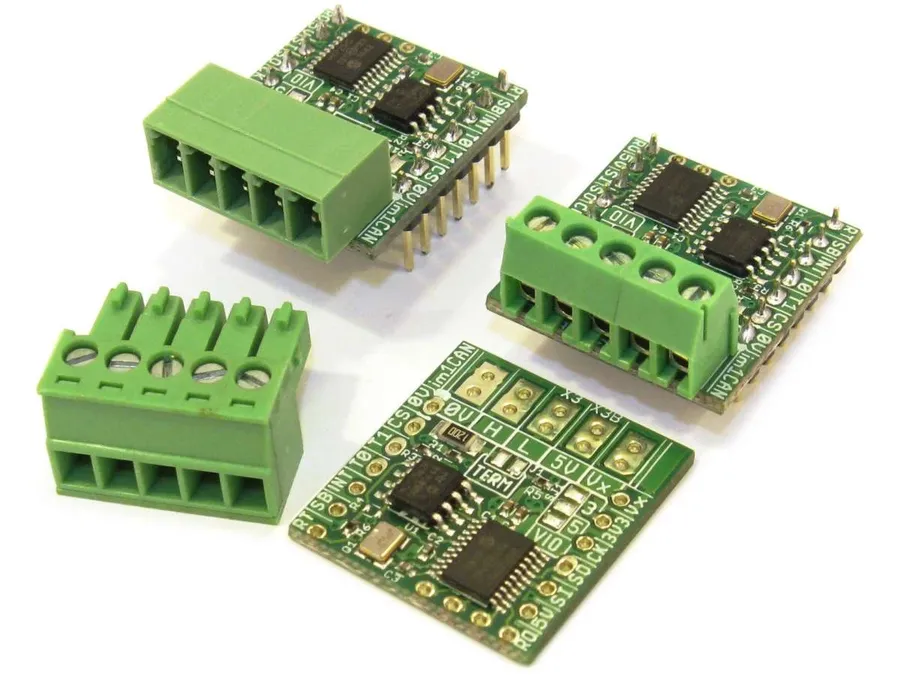
- CAN Bus Systems
Dominant in automotive electronics, industrial automation, and embedded systems, CAN bus networks rely on terminating resistors to maintain signal quality for in-vehicle communication and control. Typically, 120-ohm resistors are used at each end of the bus. - Ethernet Networks
While less explicit in common Ethernet cabling, terminating resistors are crucial in network interfaces and backplanes to ensure data transmission speeds and reliability, especially in gigabit and 10-gigabit Ethernet. - RS-485 Communication
This serial communication standard, widely used in industrial environments for its robustness, mandates terminating resistors at the ends of the bus to maintain signal integrity over longer distances. - High-Frequency Digital Circuits
In high-speed digital circuits, terminating resistors are essential to prevent signal reflections and maintain data integrity. These applications range from computer processors and memory to digital signal processing units. - Aerospace and Military Systems
Due to the stringent performance and reliability demands, terminating resistors are used to ensure reliable communication within and between components. - Telecommunications
In telecommunication systems, terminating resistors are used in signal processing and high-speed data communication circuits to minimize reflections and signal loss.
The Importance of Impedance Matching
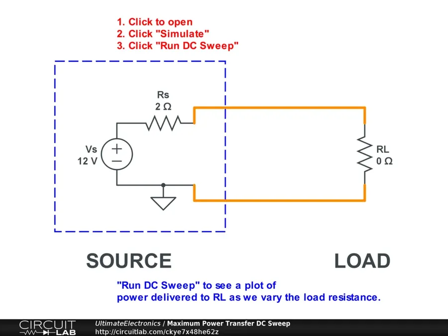
Impedance matching is paramount in transmission line systems, and the selection of a terminating resistor's value is directly tied to the characteristic impedance of that line. Typically, this impedance is either 50 ohms or 120 ohms, depending on the application. The fundamental principle behind impedance matching is to maximize power transfer and minimize signal reflections, thereby ensuring optimal signal integrity and system performance. Without proper matching, signal energy will reflect back along the transmission line, creating interference and signal loss.
| Characteristic | 50 Ohm Systems | 120 Ohm Systems |
|---|---|---|
| Typical Application | RF, Video, and High-Speed Digital Circuits | CAN bus, some digital data links |
| Signal Reflection | Low | Low |
| Impedance Matching | Requires 50 Ohm termination resistor | Requires 120 Ohm termination resistor |
| Power Transfer | Optimized for maximum power transfer | Optimized for balanced signal transfer |
| Signal Integrity | High | High |
| Common Connector Type | BNC, SMA | Screw Terminals |
The effectiveness of impedance matching can be visualized as follows: Imagine a wave traveling along a rope. If the end of the rope is fixed, the wave will reflect back. However, if the rope is connected to another rope with a different weight or if it’s left completely free the reflected wave will change dramatically. Similarly, in an electrical circuit, a terminating resistor with the correct impedance prevents the electrical signal from 'bouncing' back. The resistor absorbs the signal, preventing distortions, and maintains the signal's integrity. This absorption of signal energy rather than its reflection is key to preventing data corruption and maintaining system stability.
Terminating Resistors in CAN Bus Systems
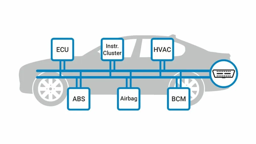
In Controller Area Network (CAN) bus systems, terminating resistors are essential components placed at each end of the bus to ensure reliable data transmission. Typically, a 120-ohm resistor is used for this purpose, acting to absorb signal energy and prevent reflections that could corrupt data or cause communication failures.
| Aspect | Description |
|---|---|
| Typical Resistor Value | 120 ohms |
| Placement | At each end of the CAN bus |
| Purpose | Prevent signal reflections and maintain signal integrity |
| Impact of Incorrect Termination | Data corruption, communication errors, and reduced system reliability |
Series vs. Parallel Termination: Understanding the Differences
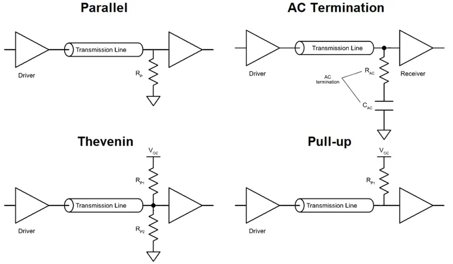
Terminating resistors are implemented in circuits using either series or parallel configurations, each serving a specific purpose in mitigating signal reflections. The choice between series and parallel termination depends heavily on the transmission line's characteristics and the desired effect on signal propagation.
| Characteristic | Series Termination | Parallel Termination |
|---|---|---|
| Primary Goal | Reduces reflections at the source (driver end) | Minimizes reflections at the load (receiving end) |
| Placement | Resistor is placed in series with the transmission line, close to the signal source. | Resistor is placed in parallel with the transmission line, close to the load. |
| Effect on Signal | Absorbs the energy of outgoing signal at the source, reducing the signal that can reflect back | Absorbs the energy of the signal reaching the load, preventing reflection from the load |
| Impedance Matching | Source impedance is matched to the characteristic impedance of the transmission line. | Load impedance is matched to the characteristic impedance of the transmission line. |
| Typical Applications | Suitable for high-speed digital signals where source reflection is a major concern, often used in single-ended signal lines. | Common in balanced transmission lines and situations where impedance matching at the load is critical for signal integrity. |
| Power Consumption | Generally, lower power consumption because the termination resistor only conducts when there's a signal being transmitted | Higher power consumption because the termination resistor is always connected to the signal line. |
Frequently Asked Questions About Terminating Resistors
This section addresses common inquiries regarding terminating resistors, their function, and best practices for their implementation in various systems.
- What exactly is a terminating resistor, and what does it do?
A terminating resistor is a resistor placed at the end of a transmission line, designed to match the characteristic impedance of the line. This impedance matching prevents signal reflections, which can distort data and cause communication errors. It effectively absorbs the signal energy, ensuring a clean and reliable signal transmission. - Why are terminating resistors so crucial in CAN (Controller Area Network) bus systems?
In CAN bus systems, signal integrity is paramount due to the real-time nature of communications. Terminating resistors, typically 120 ohms, are placed at each end of the CAN bus to prevent reflections. These reflections would lead to data corruption and communication failures. The resistors ensure that every node on the network can reliably send and receive messages. - Why is a 120-ohm resistor the standard for CAN bus termination?
The 120-ohm value is chosen because it closely matches the characteristic impedance of typical CAN bus cables. This impedance matching is critical for minimizing signal reflections and optimizing data transmission efficiency. Choosing a resistor that does not match the cable's characteristic impedance can lead to significant communication problems. - What happens if terminating resistors are not used in a CAN system?
Without terminating resistors, signals on the CAN bus will reflect back and forth, leading to signal distortion, data corruption, and ultimately, unreliable communication. This can cause devices on the network to misinterpret data or fail to communicate entirely, which can be catastrophic in critical applications such as automotive control systems. - Where should the terminating resistors be placed in a circuit?
Terminating resistors are placed at the physical ends of a transmission line or bus. In a CAN bus, this means placing one resistor at each extremity of the bus line. They should be located as close as possible to the end connectors of the bus to minimize the un-terminated line length and associated reflections. - Can a terminating resistor fail, and how would I know?
Yes, terminating resistors can fail, typically due to electrical overload, physical damage, or corrosion. A failed terminating resistor will often manifest as erratic or completely failed communication. Verification of resistor values through measurement and a check for continuity will identify such failures. - Are there different types of terminating resistors?
While the resistance value is critical, there are variations in physical construction (e.g., through-hole, surface mount) and power rating. The specific type used should depend on the operating conditions and physical constraints of the system, ensuring proper functionality and longevity. High-precision resistors may also be used when accuracy is critical.
Practical Tips for Selecting and Using Terminating Resistors

Selecting and using terminating resistors correctly is crucial for ensuring signal integrity and system reliability. This section provides actionable advice on choosing the appropriate resistor value, considering tolerance and power ratings, and proper placement on the circuit board.
- Choosing the Correct Resistor Value
The terminating resistor's value should match the characteristic impedance of the transmission line. Common impedances are 50 ohms for many RF applications and 120 ohms for CAN bus systems. Using an incorrect value will lead to signal reflections and can significantly degrade performance. - Understanding Resistor Tolerance
Resistor tolerance indicates how much the actual resistance can vary from its nominal value. Typically, 1% or 5% tolerance resistors are used, however, in high-precision circuits, 0.1% to 0.5% tolerance should be considered to achieve high accuracy. Select resistors with tolerance suitable for your application to prevent signal degradation. - Considering Power Rating
Ensure the resistor's power rating is sufficient to handle the expected power dissipation during operation. If the power rating is insufficient, the resistor can overheat and potentially fail, leading to system malfunctions. The power rating should be chosen so that the resistor will not exceed its specified temperature limit. Use the formula P=I^2*R to calculate power, where I is the current through the resistor and R is the resistance. - Strategic Placement of Terminating Resistors
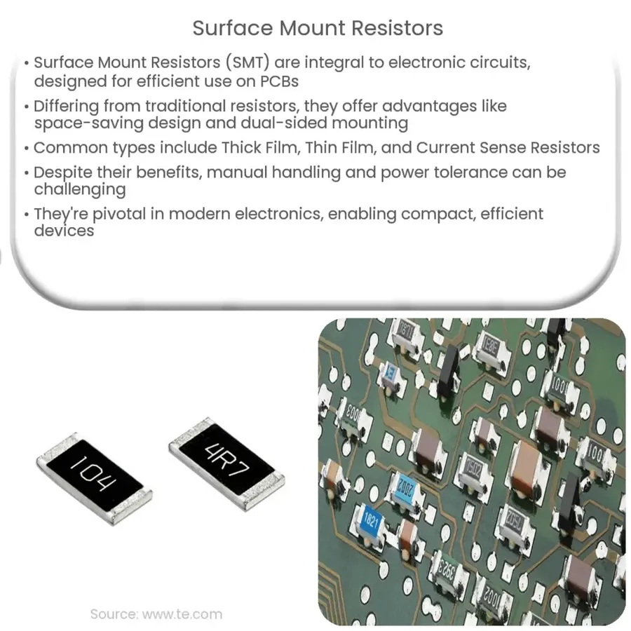
Place terminating resistors as close as possible to the end of the transmission line to minimize reflections. In systems with multiple nodes or devices, like in a CAN bus, placing a resistor at each end of the network is best practice. For parallel termination, ensure the termination resistor is at the far end from the source. For series termination the termination resistor is at the source end of the transmission line. - Using Surface Mount Technology (SMT) Resistors
SMT resistors offer smaller form factors and better performance characteristics for high-frequency applications. These are often preferred for modern circuit board designs due to their smaller footprint and better performance with lower parasitic effects - Verifying Resistance Value with a Multimeter
After placement, always verify the resistance using a multimeter to ensure the correct value is in place, and that there are no shorts or open connections. This step is crucial for preventing issues due to incorrectly selected or installed resistors.
Troubleshooting Common Issues Related to Termination Resistors
Improper termination of transmission lines can lead to a cascade of issues, primarily stemming from signal reflections. These reflections disrupt the intended signal path, causing data corruption, system instability, and overall degraded performance. Recognizing and rectifying these problems is crucial for reliable system operation.
- Signal Reflections
Signal reflections occur when the impedance of the transmission line is not properly matched by the terminating resistor. This leads to the transmitted signal bouncing back along the line instead of being absorbed. Reflected signals can interfere with incoming signals, resulting in distorted or corrupted data. - Data Corruption
Signal reflections and other impedance mismatches can cause data bits to be misinterpreted or lost entirely, leading to data corruption. This can manifest as errors in communication between devices or complete system failures, especially in data-sensitive applications. - System Instability
The cumulative effect of signal reflections, data corruption, and impedance mismatch leads to overall system instability. This may include inconsistent performance, intermittent faults, or complete system shutdown. Resolving the underlying termination issues is necessary for system integrity and reliability.
To effectively troubleshoot termination related issues, consider the following steps:
- Verify Resistor Value
Ensure that the installed terminating resistors match the characteristic impedance of the transmission line (e.g., 120 ohms for CAN bus). Using an incorrect value will result in impedance mismatch and signal reflection. Use a multimeter to accurately measure the resistance of the terminating resistors. - Check Resistor Placement
Confirm that terminating resistors are correctly placed at each end of the transmission line. Incorrect placement will render the resistors ineffective. In bus configurations like CAN, it's essential to have the resistors at the physical extremes of the bus. - Inspect Connections
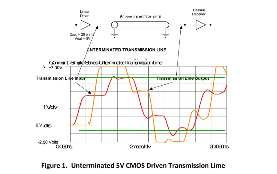
Check that the terminating resistors are properly connected to the transmission line, and look for any loose connections, solder problems, or broken traces in the circuit. Poor connections will increase impedance and lead to reflections. Use high-quality connection methods and verify the integrity of those connections. - Use an Oscilloscope for Signal Analysis
Use an oscilloscope to observe the transmitted signal. Look for reflections, ringing, or excessive overshoot or undershoot. These are clear indicators of improper termination. The signal should exhibit a clean, well-defined waveform without significant distortions. - Consider Environmental Factors
Environmental factors such as extreme temperature or humidity can affect the performance of resistors and transmission lines. Ensure that the components and systems are within their operating specifications. Replace the resistors if they show any sign of damage or degradation.
Terminating resistors might seem small and unassuming, but they are indispensable for ensuring reliable signal transmission. By understanding their function, choosing the correct type, and ensuring proper placement, we can safeguard the integrity of our electronic circuits. As technology advances, the importance of effective termination only grows, making these resistors crucial in our increasingly interconnected world. Whether it's a sophisticated industrial control system or the everyday gadgets we rely on, terminating resistors are the quiet guardians of seamless communication.