The Ultimate Guide to 1.5 uF Capacitors: Applications, Selection, and Replacement

In the realm of electrical components, the seemingly small 1.5 uF capacitor plays a critical role, often unseen but essential for the smooth operation of various devices. Like a tiny rechargeable battery, it stores energy for quick release, contributing to everything from motor start-ups to audio clarity and circuit stability. This guide provides a deep dive into the specifics of the 1.5 uF capacitor, its various applications, and how to navigate the selection process, bridging the gap between the technical and the practical for both tech enthusiasts and everyday users.
Understanding the Basics of 1.5 uF Capacitors
A 1.5 uF (microfarad) capacitor is a passive electronic component designed to store electrical energy temporarily in an electric field. The 'uF' unit represents microfarads, a measure of capacitance. Capacitors are fundamental in a wide array of circuits, and the 1.5 uF variant plays a crucial role in applications requiring specific energy storage or filtering capabilities.
Fundamentally, a capacitor consists of two conductive plates separated by a dielectric material. When a voltage is applied across these plates, an electric field develops, accumulating electrical charge. The capacitance value (measured in Farads) dictates the amount of charge the capacitor can hold for a given voltage. Therefore, a 1.5uF capacitor stores 1.5 x 10^-6 Coulombs of charge for every volt applied across its terminals.
Different Types of 1.5 uF Capacitors
The 1.5 uF capacitor rating is available across several capacitor technologies, each offering unique characteristics that make them suitable for different applications. This section explores common types such as Mylar, ceramic, film, and electrolytic capacitors, highlighting their advantages, limitations, and typical use cases.
| Capacitor Type | Material/Construction | Pros | Cons | Typical Applications |
|---|---|---|---|---|
| Mylar (Polyester Film) | Thin polyester film dielectric | Good stability, low cost, durable | Temperature sensitive, lower precision | General-purpose applications, coupling, and decoupling |
| Ceramic | Ceramic dielectric material | Small size, low cost, good high-frequency performance | Lower capacitance values, sensitive to voltage and temperature | High-frequency circuits, decoupling, and bypass capacitors |
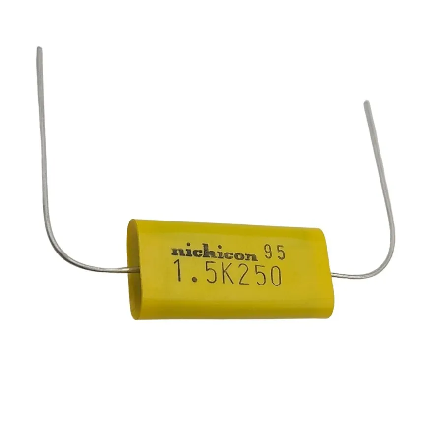
| Film (Polypropylene, Polyester) | Plastic film dielectric | High precision, good stability, low losses | Larger size compared to ceramic | Audio circuits, high-precision timing, power supplies |
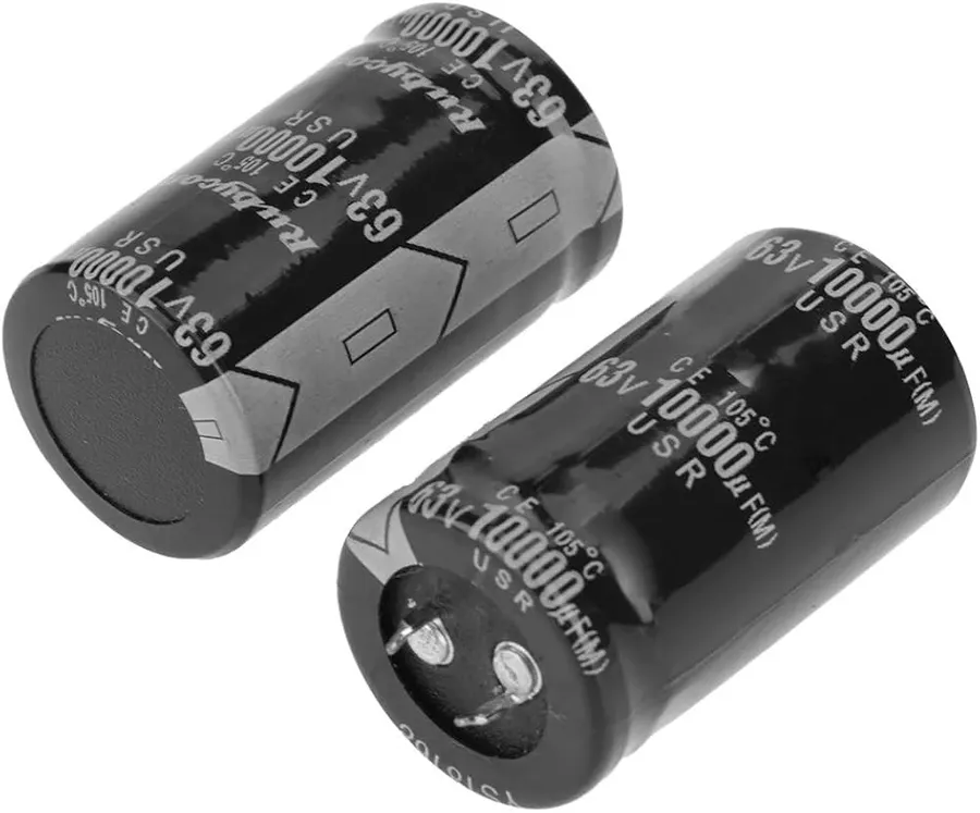
| Electrolytic | Electrolyte used as one electrode | High capacitance in small package | Polarized (AC applications requires specialized non-polar electrolytic capacitors), higher ESR | Power filtering, energy storage |
Key Specifications: Voltage, Tolerance, and Temperature Ratings for 1.5 uF Capacitors
Selecting the appropriate 1.5 uF capacitor requires a thorough understanding of its key specifications, including voltage rating, tolerance, and temperature ratings. These parameters directly impact the capacitor's performance, reliability, and longevity within its intended application. Failure to adhere to these ratings can lead to component failure or circuit malfunction.
| Specification | Description | Importance |
|---|---|---|
| Voltage Rating | The maximum voltage the capacitor can safely withstand without dielectric breakdown. | Ensures the capacitor operates within safe limits, preventing damage and potential hazards. Common ratings for 1.5uF capacitors include 250V, 450V, and 600V. The voltage rating must be equal to or greater than the maximum voltage in the application. |
| Tolerance | The permissible deviation in the actual capacitance value from its nominal (1.5 uF) value. | Impacts circuit performance and accuracy. Common tolerance ratings are ±5%, ±10%, or ±20%. A tighter tolerance is necessary for high-precision applications. A wider tolerance is acceptable in less critical applications like motor starting. |
| Temperature Rating | The temperature range within which the capacitor can operate reliably without degradation of performance. | Ensures stable operation across varying environmental conditions. Specified by minimum and maximum operating temperatures. A capacitor operating beyond its temperature rating can undergo performance degradation and premature failure. Consider the operating environment when making your selection. |
It is paramount that you not only choose a 1.5uF capacitor, but also take care to match or exceed the critical ratings such as voltage to ensure safe and reliable operation in the application the capacitor is intended to be used.
Applications of 1.5 uF Capacitors
1.5 uF capacitors are essential components in various electronic and electrical applications, primarily functioning as energy storage devices for smoothing, timing, and filtering. Their specific capacitance value makes them suitable for applications requiring precise control of electrical charge.
- Motor Starting
1.5 uF capacitors are frequently used as run capacitors or start capacitors in single-phase AC motors, commonly found in devices like mini-split air conditioners, small fans, and pumps. They provide the necessary phase shift for starting the motor and maintaining its running torque. - Audio Circuits
In audio applications, 1.5 uF capacitors are used for coupling, decoupling, and filtering. They help to block DC current while allowing AC audio signals to pass, ensuring that only the desired frequencies reach the amplifier or speaker. - Power Supplies
These capacitors play a role in power supply circuits, serving as bypass capacitors to reduce noise and ripple in the DC output. They contribute to a smoother and more stable power source for sensitive electronic components. - Lighting Systems
1.5 uF capacitors are utilized in some lighting circuits, such as fluorescent and LED drivers. They help to control the current flow and improve the power factor, leading to more energy-efficient lighting solutions. - Timing Circuits
In certain timing circuits, 1.5 uF capacitors can be combined with resistors to create time delays or oscillations. This is achieved by utilizing the charge and discharge characteristics of the capacitor.
| Application | Function | Capacitor Type (Typical) |
|---|---|---|
| Motor Starting | Phase shift for starting and running motors | Film capacitor (e.g., polypropylene) |
| Audio Coupling/Decoupling | Block DC, pass AC audio signals | Film or ceramic capacitor |
| Power Supply Filtering | Reduce noise and ripple | Electrolytic or ceramic capacitor |
| Lighting Control | Control current flow and improve power factor | Film capacitor |
| Timing Circuits | Create time delays or oscillations | Various, often ceramic or tantalum |
Selecting the Right 1.5 uF Capacitor: A Practical Guide
Selecting the correct 1.5 uF capacitor is crucial for ensuring the proper operation and longevity of electrical and electronic devices. This guide provides a systematic approach to choosing the appropriate capacitor, considering essential factors such as voltage, application, and environmental conditions, to avoid premature failure or suboptimal performance.
The selection process involves understanding the specifications of the capacitor in relation to the operational requirements of the circuit. Key factors to consider include voltage rating, application type, and operating temperature.
| Scenario | Application | Voltage Rating | Temperature Rating | Additional Considerations |
|---|---|---|---|---|
| Motor Start (Mini-Split) | Starting motor in HVAC system | 450VAC or higher | Operating Temperature of the HVAC unit | Motor specific capacitor with proper terminal configuration |
| Audio Circuit (Signal Coupling) | Coupling audio signals, filters | 50VDC or higher | Room temperature is usually adequate | Low ESR (Equivalent Series Resistance) for signal integrity |
| Power Supply (Filtering) | Power filtering in low-power circuits | 25VDC or higher, depending on power rail | Up to 85°C | Electrolytic for higher capacitance or film for better stability |
| LED Driver circuit | smoothing, timing | 100VDC or higher | Operating temperature of the equipment | Capacitor with high reliability |
| General Electronics | Timing, coupling, filtering in various circuits | 16VDC - 50VDC or higher, depending on circuit | Room temperature | Ceramic for small size, film for better precision |
Replacing a 1.5 uF Capacitor: Step-by-Step Instructions
Replacing a 1.5 uF capacitor requires careful attention to safety and proper procedures. This section provides a comprehensive guide for both motor capacitor and circuit board capacitor replacements, highlighting key differences and precautions.
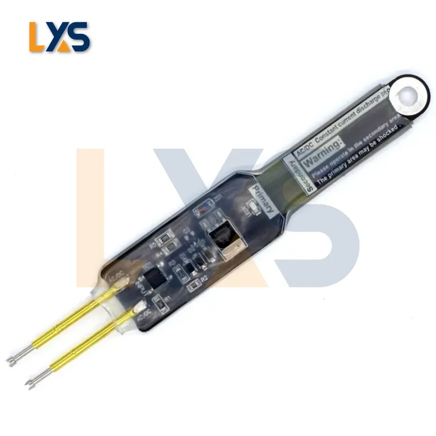
It is crucial to remember that capacitors can store an electrical charge, even when disconnected from a power source. Mishandling can lead to electric shock and damage to equipment. Therefore, proper discharge is paramount before handling. For circuit board applications, make sure to use an ESD-safe environment.
- Safety Precautions:
Always disconnect the power source before beginning any work. Verify the capacitor is discharged by using a multimeter set to measure voltage. Use insulated tools to prevent electrical shock. Wear safety glasses to protect your eyes. - Tools Needed:
Screwdrivers (Phillips and flathead), Wire strippers, Multimeter, Soldering iron and solder (for circuit boards), Insulated gloves, Replacement 1.5 uF capacitor(s)
For Motor Capacitors (e.g., in Mini-Split Systems):
- Step 1: Power Down and Discharge
Turn off and unplug the equipment. Use a screwdriver with an insulated handle to carefully short the capacitor terminals for at least 10 seconds to discharge the stored energy. Verify the capacitor is fully discharged using a multimeter by placing probes across capacitor terminals, if voltage measurement is 0 then capacitor is discharged. - Step 2: Access the Capacitor
Locate the capacitor compartment, typically behind a panel. Use screwdrivers to unscrew the access panel and expose the capacitor. - Step 3: Note the Wiring
Before disconnecting the capacitor, take a picture or make a note of how the wires are connected to the terminals. It's crucial to reconnect them in the same way. - Step 4: Disconnect the Old Capacitor
Carefully disconnect the wires from the old capacitor terminals using insulated pliers or wire strippers. - Step 5: Connect the New Capacitor
Connect the wires to the terminals of the new capacitor based on the notes or pictures taken in step 3, ensure correct polarity if the capacitor is polarized, using original wiring. - Step 6: Secure and Test
Place the new capacitor back into its compartment and secure it in place. Reinstall the access panel. Restore power and test the equipment to ensure it's working correctly.
For Circuit Board Capacitors:
- Step 1: Power Down and Discharge
Turn off and unplug the device. Discharge the capacitor by connecting a suitable resistor across the terminals for a few minutes. It is recommended to use a discharge resistor of at least 1K Ohm value to safely discharge the capacitor. Use a multimeter to check that the capacitor has discharged completely. - Step 2: Access the Capacitor
Locate the capacitor on the circuit board. This may require removing casing or other components. Make sure to use an anti-static wrist strap when handling the circuit board to avoid ESD damage - Step 3: Desolder the Old Capacitor
Use a soldering iron to carefully desolder the old capacitor from the circuit board. Use a desoldering pump or solder wick to remove excess solder. Ensure the solder pads are clean before inserting the new capacitor. - Step 4: Install the New Capacitor
Insert the new 1.5 uF capacitor into the circuit board. Ensure the capacitor is flush with the board and the leads are in the correct position for soldering and correct polarity if the capacitor is polarized. - Step 5: Solder the New Capacitor
Solder the leads of the new capacitor to the circuit board. Ensure the solder joints are strong and clean. Use a small tip for precise solder joint, also use a flux to increase joint quality. - Step 6: Reassemble and Test
Reassemble the device. Restore power and test the equipment to ensure it's working correctly.
It is important to check and verify the device is functioning properly after replacement. If there is any malfunction immediately power down the device and check the wiring or soldering joints. It is important to follow the above mentioned steps diligently and cautiously for proper replacement.
Troubleshooting and Frequently Asked Questions about 1.5 uF Capacitors
This section addresses common issues encountered with 1.5 uF capacitors, providing practical troubleshooting advice and answers to frequently asked questions. Understanding failure modes and proper diagnosis techniques ensures reliable performance and safe operation of devices utilizing these components.
- Why do 1.5 uF capacitors fail?
1.5 uF capacitors fail due to various reasons, including exceeding their voltage or temperature ratings, physical damage, manufacturing defects, or dielectric breakdown over time. Capacitors used in AC circuits can degrade from the constant charging and discharging cycles. Electrolytic types can dry out or leak, leading to reduced capacitance or total failure. - How can I diagnose a faulty 1.5 uF capacitor?
A faulty 1.5 uF capacitor can be identified through several methods. Visually inspect for swelling, bulging, or leaks, especially in electrolytic capacitors. Use a multimeter to measure capacitance and ESR (Equivalent Series Resistance). A significantly lower capacitance than the rated value or a high ESR indicates a failing capacitor. In circuits, a faulty capacitor might manifest as overheating, intermittent operation, or complete device failure. - Can I use a 2.0 uF capacitor to replace a 1.5 uF capacitor?
Replacing a 1.5 uF capacitor with a 2.0 uF capacitor should generally be avoided unless the circuit design specifically allows for it. A higher capacitance can alter circuit timing, resonant frequencies, and impedance characteristics. In some cases, particularly in motor start circuits, it might result in decreased motor performance or damage. Always consult the device's specifications before making a replacement with a different capacitance value. If the application is not critical, and the voltage rating is the same, slight variations are acceptable, but sticking to the original value is best practice. - What happens if I use a capacitor with a higher uF rating than required?
Using a capacitor with a higher uF rating can lead to several potential issues, depending on the application. In timing circuits, it will significantly alter the timing. In motor start circuits, it can lead to increased current draw, overheating, and premature failure of the motor and/or capacitor. Generally, using a much higher capacitance than specified is not recommended and should only be done after careful evaluation of the circuit. - What does uF mean on a capacitor?
The abbreviation 'uF' stands for microfarad, which is a unit of capacitance. A farad is a unit of electrical capacitance, equal to the capacitance of a capacitor in which a charge of one coulomb produces a potential difference of one volt. A microfarad (µF) is one millionth of a farad (10^-6 farads) and is a more practical measurement for capacitors used in most electronic circuits. Capacitance is a measure of a capacitor's ability to store electrical charge. - What is the difference between AC and DC capacitors?
AC (Alternating Current) capacitors and DC (Direct Current) capacitors are designed for different operating conditions and voltage types. AC capacitors are typically non-polarized film capacitors, designed to withstand constantly changing polarity, and often used in applications like motor starters and power factor correction. DC capacitors, often electrolytic types, have polarity and are designed for stable DC voltages. They are used for filtering and energy storage. Using a DC capacitor in an AC application can lead to catastrophic failure, and vice versa a AC capacitor might not work as intended in a DC application. - What are the common failure signs of a 1.5uF capacitor in an AC motor application?
In an AC motor application, common failure signs of a 1.5uF capacitor include the motor failing to start, running with reduced torque, overheating, or making unusual noises. These issues often indicate that the capacitor is no longer providing the necessary phase shift in the motor's windings. A visual inspection of the capacitor for bulging or leaks can also help diagnose a capacitor failure.
Where to Buy 1.5 uF Capacitors
Sourcing 1.5 uF capacitors requires careful consideration of several factors to ensure you obtain the correct component for your specific application. This section outlines various retailers and suppliers, as well as key aspects to evaluate when selecting a vendor.
- Online Retailers
Major online platforms such as Amazon and eBay provide a wide selection of 1.5 uF capacitors from various sellers. It's crucial to verify the seller's ratings and reviews, as well as the capacitor's specifications, to ensure you are receiving a genuine and suitable product. - Specialized Electronic Component Suppliers
Reputable electronic component distributors, including Mouser Electronics, Digi-Key Electronics, and Arrow Electronics, offer a diverse range of 1.5 uF capacitors. These suppliers are known for providing detailed technical specifications, datasheets, and traceability, which are critical for engineering and professional applications. These are reliable sources to ensure product authenticity and specifications. - Local Electronics Stores
Local electronics stores may carry a limited selection of 1.5 uF capacitors. This can be a convenient option if you need a capacitor quickly. However, selection and pricing may not be as competitive as online retailers. - Factors to Consider When Choosing a Vendor
Prioritize reputable vendors with a track record of selling authentic products. Analyze price to ensure the components are within your budget while meeting your quality needs. Compare lead times for shipping to ensure the component is available when you need it. Check if the supplier offers datasheets or other technical support. Ensure the vendor has transparent return policies. - Importance of Verifying Product Parameters
Before making a purchase, meticulously check the product parameters to ensure they match your requirements, including the voltage rating, tolerance level, temperature rating, and physical dimensions. If the application requires an AC capacitor (e.g., for motors), do not use a DC capacitor as a replacement. Failure to do so can lead to circuit malfunction or component failure.
Future Trends in 1.5 uF Capacitor Technology
The field of capacitor technology is continually evolving, and these advancements will inevitably impact the future of 1.5 uF capacitors. Ongoing research and development are focused on enhancing performance, reducing size, improving reliability, and expanding the range of applications. These trends promise to make 1.5 uF capacitors more versatile and efficient in the years to come.
- Miniaturization
The push for smaller electronic devices is driving the demand for more compact capacitors. Future 1.5 uF capacitors will likely be smaller and have higher volumetric efficiency, allowing for their integration into increasingly space-constrained applications. This is achieved through advanced material science and manufacturing techniques. - Improved Materials
New dielectric materials with higher permittivity and lower losses are constantly being developed. These materials will lead to capacitors with improved performance, higher energy density, and greater stability over a wider range of temperatures. This includes research into advanced ceramics, polymers, and nanomaterials. - Enhanced Temperature Stability
Capacitors often need to operate reliably across a wide range of temperature conditions. Future 1.5 uF capacitors are likely to have enhanced temperature stability, ensuring consistent performance in harsh environments, thus broadening their applicability in demanding fields such as automotive and aerospace. - Increased Voltage Ratings
Advances in material science and manufacturing processes will enable the development of 1.5 uF capacitors with higher voltage ratings without increasing physical dimensions. This will be beneficial for power electronics applications, facilitating better energy storage and management. - Self-Healing Capacitors
Self-healing capacitors are an emerging area of interest, particularly for applications requiring high reliability. Future 1.5 uF capacitors may incorporate self-healing properties to recover from minor breakdowns, thus extending their operational lifespan and improving overall system reliability. These self-healing capabilities are often achieved by incorporating special materials within the capacitor's structure. - Integration with other components
The trend toward integrated circuits will likely extend to passive components such as capacitors. Future 1.5 uF capacitors may be fabricated on the same substrate as other microelectronic devices, enabling further miniaturization and simplification of electronic assemblies.
The 1.5 uF capacitor, a small but mighty component, is crucial in countless electronic devices, from the precise timing circuits to motor start-ups. Understanding its various types, applications, and selection criteria, is critical for anyone working with or replacing electronics. Like a reliable heart in an electronic system, the 1.5 uF capacitor ensures functionality and performance. As technology advances, we can expect these capacitors to become even more reliable and efficient. With that knowledge, you can better choose, apply and replace these vital components.